Extended Kinematic Equation - An Explanation of Mats Järlström's
←
→
Page content transcription
If your browser does not render page correctly, please read the page content below
TOOL

                                                                                                                                             Shutterstock/jpreat
                 An Explanation of Mats Järlström’s
Extended Kinematic Equation                          By Jay Beeber (M)

S
                       ince the yellow indication was first added to traffic signals in 1920, the proper interval
                       duration has been robustly debated.1 Seemingly, the timing of the yellow indication
                       appears straightforward. However, determining the illumination interval is quite
                       intricate since it is part of a complex system of physical and human-made laws,
technology, and human behavior that all must operate compatibly.
In 1960, Denos Gazis, Robert Herman, and Alexei A. Maradudin             GHM’s solution to regulate a yellow change interval first
(GHM) provided a scientific solution to the yellow change interval   appeared in the 1965 ITE Traffic Engineering Handbook, and it
question in their paper, “The Problem of the Amber Signal Light      has become known as the kinematic equation.3 However, GHM’s
in Traffic Flow.”2 GHM presented a kinematic solution to a binary    solution is limited to vehicles traveling through level intersections
STOP or GO dilemma when a driver is faced with the onset of a        at constant velocity, which does not include vehicle deceleration to
yellow signal indication. The problem GHM solved and eliminated      execute safe turning maneuvers. This article presents a brief review
was an area in the roadway known as the “dilemma zone”, where a      covering GHM’s original solution and Mats Järlström’s extended
driver-vehicle complex could neither STOP safely and comfortably     kinematic equation which allows for vehicle deceleration and
nor GO without the need to violate the red or accelerate unsafely    turning maneuvers.4
into the intersection.

34   Ma rc h 2 0 2 0   i t e j o u rn al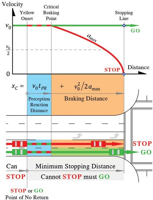
GHM’s Solution
The foundation of GHM’s solution is a minimum safe and
comfortable DISTANCE to STOP, defined as the “critical distance”
(xC), which is composed of an allocated perception-reaction
distance (xPR) plus a minimum braking distance (xBr). It is expressed
mathematically as:
v20
xC = xPR+ xBr= v0• tPR+ _____ (1)
2amax
Where:
xC= Critical distance - the minimum safe and comfortable stopping
distance, (feet [ft.] or meters [m])
v0= Maximum uniform (constant) initial/approach velocity, (foot
per second [ft./s] or meter per second [m/s])
tPR= Maximum allocated driver-vehicle perception-reaction time, (s)
amax= Maximum uniform (constant) safe and comfortable decelera-
tion, (ft./s2 or m/s2)
GHM’s GO solution is the minimum TIME needed for a vehicle
to travel across the critical distance (xC) and is thus the minimum
yellow change interval (Ymin) required to eliminate the dilemma
zone. The solution is calculated by dividing the critical distance by
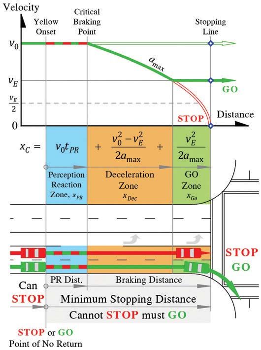
the vehicle’s maximum constant velocity across that distance. For Figure 1. GHM’s minimum STOP and GO equations plotted and
driver-vehicles that maintain their initial velocity (v0) across the referenced to a signalized intersection.
critical distance, this is expressed mathematically as:
v20
_____ Limitations of GHM’s Kinematic Equation
tPR _2a
xc v_0___ max
Ymin = __
v0 = v0 + v0
____
(2) An essential concept to be recognized is that GHM’s Kinematic
Equation can only be derived if both the initial velocity (v0) which is
Which reduces to the well-known kinematic equation: used to calculate the minimum stopping distance and the vehicle’s
velocity while traversing the minimum stopping distance are the
v0
Ymin = tPR+ _____ (3) same. Where a vehicle must slow down for any reason, such as to
2amax
negotiate a turn, the initial velocity (v0) and the vehicle’s velocity
Since restrictive yellow laws (drivers must not enter the inter- while traversing the critical distance are NOT the same and GHM’s
section on yellow) prevailed in their jurisdiction, GHM’s original Kinematic Equation cannot be used. This point has been reiterated
yellow time solution also included the minimum clearance interval in correspondence by Dr. Alexei A. Maradudin, the sole surviving
(tCl) to allow a vehicle with length (L) to travel straight through and author of the original GHM paper:5
exit an intersection with a width (w), expressed as: “This formula which we derived, cannot be applied to turning lanes
or to any situation where the driver must decelerate within the critical
w+L
tCl = _____
v0 (4) distance. The formula can only be applied to vehicles which start at the
maximum allowable speed measured at the critical stopping distance
Internationally, “permissive” yellow change laws (driver-vehicles and which proceed at a constant speed into the intersection.”
may enter the intersection during the entire yellow interval) are Järlström has devised a new protocol to extend the kinematic
most common and the clearance interval function is often handled equation for situations where a vehicle must slow down within the
by employing a separate “all-red” interval. minimum stopping distance based on GHM’s logic.
Figure 1 illustrates the above concepts for both restrictive (YR)
and permissive (YP ) yellow timing policies. GHM’s Logic Extended to Turning Movements
This article promotes the most common permissive yellow A central axiom of traffic signal timing is that, at the onset of the
change interval timing policy, but practitioners should note that yellow indication, a “reasonable” driver farther from the intersec-
where restrictive yellow laws prevail, the yellow interval must also tion than their minimum stopping distance (critical distance) has
handle the clearing function. sufficient distance to stop comfortably and should do so. Likewise,
www.ite.org Ma rch 2 0 2 0 35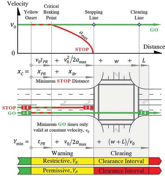
a “reasonable” driver closer to the intersection than their critical      the stopping distance while decelerating from the initial approach
distance proceeds into the intersection when presented with a             velocity (v0) to the intersection entry velocity (vE) to safely and
yellow indication. Figure 2 illustrates this concept.                     comfortably negotiate a turning maneuver.
     The logic behind the methodology for determining the duration            In contrast to the condition where a driver approaches a
of the yellow change interval is that the interval should provide         signalized intersection in a through lane, scenarios where a driver
a reasonable driver who is too close to the intersection to stop          approaches a signalized intersection in a turning lane are signifi-
safely and comfortably (i.e., closer than the critical distance) with     cantly more complicated. Although there is a range of possibilities as
adequate time to traverse the minimum stopping distance and               to where a driver might begin to decelerate on approach to the inter-
legally enter the intersection before the signal turns red.               section, the extended solution presented in this article is based on a
     A reasonable driver is defined as one who is not violating the law   model of driver-vehicle motion which encompasses the “worst-case
(i.e., acting legally), and whose chosen actions are rational, prudent,   scenario” or “boundary condition” for a decelerating vehicle. A full
and feasible. Safety and equity requires that the motion of any roadway   explanation of this concept and examination of other models of
user who exhibits reasonable behavior must be accommodated within         driver-vehicle motion is presented in “Yellow Change Intervals for
the signal timing protocol, even if their chosen actions are not the      Turning Movements Using Basic Kinematic Principles,” available
“average” or most common to be encountered upon the roadway.              on the ITE website at www.ite.org/technical-resources/topics/
     In conformance with the standard for through lane movements,         traffic-engineering/traffic-signal-change-and-clearance-intervals.
the calculation of the minimum yellow change interval for turning
movements must also provide a reasonable driver adequate time             Järlström’s Extended Kinematic Equation
to traverse the minimum stopping distance and legally enter the           For the extended solution, conceive that the driver begins their
intersection before the onset of the red indication. This calculation     deceleration at the Critical Braking Point, decelerating at their
must allow for the extra time necessary for a vehicle to traverse         maximum safe and comfortable deceleration (amax) to their target
                                                                          entry velocity (vE) and then traverses the remainder of the braking
                                                                          distance at this velocity into the intersection.
                                                                               Under this “boundary condition” model for a decelerating vehicle,
                                                                          the minimum stopping distance (xC) is divided into three distinct
                                                                          areas of vehicle movement: 1) the Perception-Reaction zone (xPR), 2)
                                                                          a Deceleration Zone (xDec) where the driver decelerates to their target
                                                                          entry velocity (vE) beginning at the Critical Braking Point, and 3) a
                                                                          Non-Deceleration “Go Zone” (xGo) starting at the end of the Decelera-
                                                                          tion Zone where the driver continues at their target entry speed to the
                                                                          limit line and into the intersection. Figure 3 illustrates these concepts.
                                                                               The minimum time to traverse the minimum stopping distance
                                                                          is, therefore, the combination of 1) the time to traverse the
                                                                          perception-reaction distance (tPR), plus 2) the time to traverse the
                                                                          Deceleration Zone (tDec), plus 3) the time to traverse the Go Zone
                                                                          (tGo). This combination is the minimum yellow change interval
                                                                          (Ymin) necessary to eliminate the dilemma zone for this model of
                                                                          driver-vehicle motion, expressed as:

                                                                             Ymin = tPR + tDec + tGo                                             (5)

                                                                             The time to traverse the Deceleration Zone is given by:

                                                                                      (v – v )
                                                                                        0   E
                                                                             tDec =   _______
                                                                                                                                                (6)
                                                                                        amax

                                                                              The time to traverse the Go Zone (tGo) is determined as follows:
                                                                              First, calculate the length of the Go Zone (xGo) by subtracting
Figure 2. Illustration of the STOP or GO scenario encountered when        the length of the Deceleration Zone (xDec) from the full braking
approaching a signalized intersection.                                    distance (xBr).

36   Ma rc h 2 0 2 0   i t e j o u rn al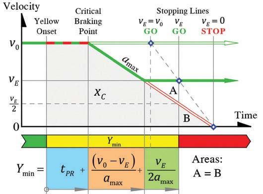
Therefore, the minimum time to traverse the minimum
                                                                          stopping distance (by definition, the minimum yellow change
                                                                          interval, Ymin) for a vehicle that decelerates within the critical
                                                                          distance to negotiate a turn is given by:

                                                                                         (v0 –vE_) _____
                                                                                                     v
                                                                             Ymin = tPR+ _____    + E                                               (11)
                                                                                          amax     2amax

                                                                            Algebraic simplification of the Järlström’s extended kinematic
                                                                          model shown in Equation 11 yields:

                                                                                         v0 –½v_E
                                                                             Ymin = tPR+ _____                                                      (12)
                                                                                          amax

                                                                              Where (v0 ≥ vE > 0):
                                                                          Ymin = Minimum yellow change interval (s)
                                                                          v0 = Maximum uniform initial/approach velocity, (ft./s or m/s)
                                                                          vE = Maximum intersection entry velocity, (ft./s or m/s)
                                                                          tPR= Maximum allocated driver-vehicle perception-reaction time, (s)
                                                                          amax = Maximum uniform safe and comfortable deceleration, (ft./s2
                                                                          or m/s2)
                                                                              Figure 4 illustrates the extended kinematic model compared
                                                                          to GHM’s STOP or GO solutions across the critical distance (xC)
                                                                          referenced to time.
                                                                              The validity of Järlström’s Extended Kinematic Equation is
                                                                          established in the following manner:
                                                                              When vE = v0 (constant velocity), the protocol yields the ITE
                                                                          Kinematic Equation applicable for through movements (Equation 3).
Figure 3. Zones of driver-vehicle motion while decelerating to                When vE = 0 (zero end velocity), the protocol yields the equation
negotiate a turn.                                                         to calculate the minimum time to come to a complete stop:

                                                                                              v0 _
    Since the length of the Deceleration Zone (xDec) equals the              tStop = tPR+   ____
                                                                                                                                                    (13)
                                                                                             amax
vehicle’s time to traverse the Deceleration Zone (tDec) multiplied by
the vehicle’s average velocity (vav):
                                          2      2
                    (v0 + v E) _______
                               (v – v ) v0 – v E
   xDec = vavtDec = _______   • 0 E =_______                        (7)
                       2          amax    2amax

   And, from the last term of Equation 1, the braking distance is:
             2
            v0
   xBr =   _____
                                                                    (8)
           2amax

   The length of the Go Zone is:
                        2        2     2       2
                       v0     v – v E _______
                                            vE
   xGo = xBr–xDec = ______  – _0______   =                          (9)
                      2amax      2amax     2amax

    The time to traverse the Go Zone (tgo) equals the length of the
Go Zone (xgo) divided by the vehicle’s velocity across this distance
(the driver’s target entry velocity (vE)):
                vE2
               ____
         xGo _2a          vE                                              Figure 4. Time model including vehicle deceleration traversing the
    tGo =___ = ____
                  max
                      = _____                                      (10)
          vE     vE      2amax                                            minimum stopping distance.

                                                                                                                   www.ite.org     Ma rch 2 0 2 0    37
Note that stopping vehicles will reach the limit line after the         5. The benefit of the extended kinematic equation is to provide
signal has changed to red and, for these vehicles, the length of the           a sufficient yellow change interval for all driver-vehicle
yellow interval is irrelevant.                                                 movements to eliminate the dilemma zone and reduce red-light
                                                                               violations. Practitioners should be aware that red-light
Additional Considerations                                                      violations may increase in turning lanes if the available green
1. The methodology for determining the length of the yellow                    time is reduced to accommodate longer yellow intervals. This is
   change interval described by both the classic and extended                  especially true where the green interval is insufficient to clear
   kinematic equations incorporates the following presumptions:                the queue. Rather than reducing the green interval, practitioners
   a) The vehicle travels in free-flow conditions (unimpeded                   may consider increasing the cycle length instead.
        movement, no queue, etc.).                                          6. Practitioners may have concerns about yellow intervals that are
   b) The yellow indication illuminates at the moment the vehicle              “excessive,” resulting in drivers stopped at the signal still viewing
        arrives at the critical distance.                                      a yellow indication. However, yellow intervals calculated using
   c) When the yellow illuminates, the vehicle’s initial approach              the extended solution do not exceed the minimum time required
        velocity (v0) is the actual or estimated 85th percentile speed         for a vehicle to come to a safe and comfortable STOP (Equation
        or the posted limit, whichever is higher.                              13). Therefore the circumstance of a stopped driver facing a stale
2. The extended kinematic equation presented here yields the                   yellow light should typically not occur. itej
   minimum yellow interval for a level intersection approach.
   As with the kinematic equation for through movements,                    References
   grade adjustments should be made for vehicles approaching                1. “Traffic Lights Invented by William L. Potts,” Mark Traffic. http://www.
   on a downgrade.                                                             marktraffic.com/traffic-lights-invented-by-william-l-potts.php. (Accessed
3. The assumed intersection entry velocity should be determined                January 26, 2020).
   using engineering judgment. Generally, drivers entering an               2. D. Gazis, R. Herman and A. A. Maradudin, “The Problem of the Amber Signal
   intersection to conduct a left turn, do so at approximately 20 miles        Light in Traffic Flow,” Operations Research, vol. 8, no. 1, pp. 112-132, 1960.
   per hour (mph) (32 kilometers per hour [km/hr]) depending on             3. J. E. Baerwald, “Traffic Signalization, Yellow Interval,” in Traffic Engineering
   the intersection radius. Right-turning drivers generally negotiate          Handbook, Washington, DC, Institute of Traffic Engineers (ITE), 1965.
   the turn at approximately 12 mph (19 km/hr). An entry speed              4. M. Järlström, “An Extended Kinematic Equation,” http://jarlstrom.com/
   can also be estimated based on the curve design speed published             PDF/An Extended Kinematic Equation.pdf. (Accessed January 26, 2020).
   by ITE.6 For a full explanation of this calculation, see “Yellow         5. A. A. Maradudin to the Institute of Transportation Engineers, July
   Change Intervals for Turning Movements Using Basic Kinematic                29, 2015. Letter. https://www.thenewspaper.com/rlc/docs/2015/
   Principles,” available at www.ite.org/technical-resources/topics/           maradudin15.pdf. (Accessed January 26, 2020).
   traffic-engineering/traffic-signal-change-and-clearance-intervals.       6. Traffic Engineering Handbook, 6th Edition. Washington, DC: Institute of
4. Calculating tolerance is standard engineering practice and                  Transportation Engineers, 2009.
   should be employed in calculations of the minimum yellow                 7. McGee, H., et al. NCHRP Report 731: Guidelines for Timing Yellow and All-
   change interval. Perception-reaction time, deceleration, approach           Red Intervals at Signalized Intersections. Washington, DC: Transportation
   velocity, and entry velocity are not constants. A reasonable range          Research Board of the National Academies, 2012.
   of values for each of these parameters is applicable for every           8. Harwood, DW., et al. NCHRP Report 505: Review of Truck Characteristics
   driver-vehicle complex approaching a signalized intersection.               as Factors in Roadway Design. Washington, DC: Transportation Research
   Driver-vehicles whose metrics fall within a reasonable range                Board of the National Academies, 2003.
   but do not strictly match the parameters typically chosen by the
   traffic engineer should be accommodated.                                               Jay Beeber (M) is executive director of Safer Streets
        For example, research shows that the 85th percentile PRT                          L.A., a public policy and research organization
   is closer to 1.5 seconds (sec.) rather than the traditionally                          dedicated to the adoption of scientifically sound and
   accepted PRT of 1.0 sec.7 Likewise, some drivers, as well as                           sensible transportation practices. He has authored
   larger vehicles, cannot safely and comfortably decelerate at 10                        numerous research reports on transportation safety
   ft./s2 (3.05 m/s2) and employ a deceleration of 8.0 ft./s2 (2.44 m/s2)   issues and was a featured presenter at the ITE’s Annual Meeting in
   or less.8 Therefore, engineering tolerances should be employed           2016. He has served on a number of transportation related working
   within signal timing protocols to accommodate all reasonable             groups including subcommittees on Statewide Traffic Signal Timing
   driver-vehicle combinations, especially where the rate of                for the California Traffic Control Devices Committee and the
   red-light violations is higher than acceptable.                          California Zero Fatalities Taskforce.

38   Ma rc h 2 0 2 0   i t e j o u rn al


You can also read