Ice and Snow Detector 1871-ESM (for gutter heatings) 1872-ESM (for slab heatings)
←
→
Page content transcription
If your browser does not render page correctly, please read the page content below
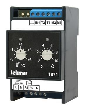
Ice and Snow Detector
1871-ESM (for gutter heatings)
1872-ESM (for slab heatings)
Installation and Adjustment Instructions
Content
    Scope of delivery ............................................ 3
    Overview.......................................................... 4
    Terms and functions........................................ 6
    Installation ....................................................... 8
    Commissioning and adjustment .................. 10
    Troubleshooting............................................ 11
    Parameter setting.......................................... 13
    Technical data ............................................... 18

                                                                                        Safety instructions

                                                                             Always observe the attached safety instructions and
                                                                             the general regulations for electrical installation
                                                                             during installation and operation of the device!

2
Scope of delivery
Ice and Snow Detector
1871-ESM or
1872-ESM
Ice and Snow Detector
1871-ESM (for gutter heatings)
1872-ESM (for slab heatings)
Safety Instructions
3Overview time, are pre-defined with factory settings and can
Tekmar ice detection systems use their combi sen- be adjusted if required via a parameter setting
sors to measure temperature and moisture in mode. Two three-colour LEDs are provided to indi-
heated outdoor areas such as open spaces, roofs cate the operating status.
and gutters. This means that they operate in a par- The model 1871 with sensor 3354 is ideally suited
ticularly energy-efficient way, since the heating is for use with gutter heating systems, the model 1872
only switched on when it is cold or if there is water, with sensor 3356 for small to medium-sized electri-
ice or snow. cal slab heating systems.
The 73 ice detection system is an all-round system Functions
wherever it is necessary to keep an area free of ice control and monitoring of one sensor and one
and snow: It is flexible, maintenance-free and inex- heating circuit
pensive. Two different sensor types guarantee that continuous temperature monitoring in the
the system can be used in all areas. heated area
All system 73 control devices are easy to install and activation of the moisture measurement if the
commission. temperature falls below the activation tempera-
Ice and snow detectors ture
The two ice and snow detectors 1871-ESM and start of the minimum heating time if the moisture
threshold is exceeded on the sensor, alterna-
1872-ESM are ideal as entry-level models, especi-
ally for controlling small systems with one tempera- tively by an external signal at the control input
ture and moisture sensor and one heating circuit. deactivation of the heating if the temperature
An uncomplicated commissioning is achieved by falls below the switch-off temperature (lower
only two rotary adjusters for setting the activation temperature limit)
temperature and the moisture threshold. output relay with 16 A - ideal for connecting
Further parameters, such as the lower temperature smaller systems without contactor
limit, the minimum heating time and the follow up
4Overview
Sensors Documentation
The System 73 sensors use a measuring principle Other relevant documentation:
based on the thermal capacity of the sensor surface Safety Instructions
and the water on it, possibly in the form of ice or
snow. This measuring principle was developed by I-187x-ESM-Sensor-EN:
tekmar and has already proven itself over many summarised extract from M-MES-Sensorik
years. Only one sensor is required to measure (Installation instructions for sensors of the T,
moisture and temperature, making installation very TF-E und TF-S systems, available in German
simple and cost-effective. only)
System 73 offers two types of sensors: The 3356
sensor is ideally suited for installation in open spaces
such as roads, walkways or staircases. The 3354
sensor can be mounted, for example, in gutters and
on roof surfaces thanks to its design with axial cable
connection. Both sensors are characterised by a
compact and robust design, which is achieved by the
casing made of high-quality, corrosion-resistant brass
and the microbe-proof, longitudinally watertight cable.
The sensors can be used for a wide variety of re-
quirements due to the comprehensive range of
accessories for their installation and mounting. This
also optimises installation and maintenance costs.
5Terms and functions the system switches on the heating system too late,
Activation temperature (upper temperature limit) the moisture threshold should be reduced.
Note: If the moisture threshold is too low, the
If the temperature of the combi sensor - and thus of
heating system may be permanently activated
the heated area - falls below the defined activation
during times when the temperature is below the acti-
temperature, the moisture measurement will be acti-
vation temperature. This can lead to increased ener-
vated and, if necessary, the heating circuit will be
gy consumption. In general: the lower the moisture
switched on. If the temperature rises above the acti-
threshold, the higher the energy consumption.
vation temperature, a possibly activated heating cir-
cuit will be switched off and the moisture measure- Moisture measurement
ment will be deactivated. Below the activation temperature, the moisture mea-
Moisture threshold surement is repeated at regular intervals until a mo-
isture value above the moisture threshold is detected
The moisture threshold can be used to adjust the
or until the activation temperature is exceeded again.
sensor's sensitivity with regard to the detection of
If moisture is detected, the heating circuit switches on
water, ice or snow on the sensor. The moisture
for the minimum heating time and the moisture mea-
threshold can be set within a range of 0 to 10. Low
surement is suspended. Only after the minimum hea-
values mean high sensitivity.
ting time has elapsed is the moisture determined
The basic setting for the moisture threshold should again at regular intervals. Depending on the result of
be 1 to 2 points above the dry value indicated on the the moisture measurement, the heating circuit
sensor. remains switched on or is deactivated.
If the system switches the heating system on too The system automatically optimises the duration of
early, i.e. if there is very little moisture or the sensor a measuring cycle depending on the sensor type
is dry, the moisture threshold should be increased. If and temperature.
6Terms and functions
Switch-off temperature (lower temperature limit) ever, the minimum heating time is discontinued if
In addition to the activation temperature, there is also the activation temperature is exceeded.
a lower temperature limit (the switch-off tempera- The factory setting of the minimum heating time of
ture), below which the moisture measurement and, if 30 (Type 1871) or 90 (Type 1872) minutes can be
necessary, the heating are deactivated again. adapted to the local conditions via parameter set-
At very low outside temperatures, dripping condensa- ting.
tion no longer occurs in roof areas and snowfall is no Follow up time
longer to be expected in open spaces. (If snow falls, After the monitored area has thawed and dried with
it will be dry, light and not slippery. Since in this case the help of the heating, i.e. when the combi sensor
the heating capacity is often not sufficient to comple- no longer detects moisture, a follow up time can be
tely defrost the surface and it would only be partially activated. In the event that the combi sensor cannot
thawed instead, the risk of slipperiness would be be optimally positioned, the follow up time can be
rather increased by switching on the heating system). used to ensure that any ice and snow residues are
The factory setting of the switch-off temperature is also defrosted, e.g. in shaded areas.
optimised for European conditions at -15°C and can In the factory setting, the follow up time is switched
be changed via parameter setting. off. It can be switched on via parameter setting.
Minimum heating time
If moisture above the moisture threshold is detected
after the temperature has fallen below the activation
temperature, the minimum heating time starts,
which ensures that the heated area is definitely de-
frosted. During the minimum heating time, no
further moisture measurement takes place. How-
7Installation Installation procedure
Proper use Only qualified personnel (electrician or simi-
lar qualification) may install the device. The
The device has been solely designed to con-
relevant engineering practices and the enclosed
trol electric heating systems and must only
safety instructions must be observed.
be used for this purpose. It has to be installed in an
electric distributor (fuse box or control cabinet) and Disconnect the control cabinet before installation.
connected to the existing heating system. When Mount the device on a 35 mm mounting rail in a
doing so it is absolutely necessary to observe all subdistribution unit or another adequate housing.
Technical data. Any different or improper use of the Wire it according to the following illustration.
device may cause defects in the device and/or life-
Protection against contact according to protection
threatening states and situations. Additionally all
class II is guaranteed by the following measures:
guarantee claims are forfeited in such a case.
Installation in small distribution boards according to
DIN 57603/VDE 0603 (e.g. distributor of the N-
system)
or
DIN 57659/VDE 0659
The regulations according to VDE 0100 must be ob-
served!
8Installation
Connection of the device Notes:
An external button on input A, which is switched to L,
can be used to manually activate the defined mini-
mum heating time. When the button is pressed, the
heating is switched on for the duration of the mini-
mum heating time, irrespective of the measured tem-
perature and moisture.
With a bridge between terminal IN1 and the adjacent
ground connection, the parameter setting mode can
be started in order to define further parameters. For
detailed information on setting the parameters refer
to section Parameter setting on page 13.
9Commissioning and adjustment System displays upon start-up
Setting the temperature and moisture values L R Description
Use the rotary adjusters on the front of the device to no supply voltage
set the two basic parameters during operation, i.e. hardware error
the activation temperature (upper temperature limit) software error
and the moisture threshold. Changes take effect im- software initialisation
mediately. reset to factory settings ongoing
reset to factory settings completed
• left: activation temperature device check ongoing
(upper temperature limit), device check error
range: -3 to +5°C label/application error
• right: moisture threshold, software start
range: 0 to 10
Status displays during operation
Note: If the moisture threshold is too low, the
heating system may be permanently activated L R Description
during times when the temperature is below the acti- several seconds after power-up
vation temperature. This can lead to increased ener- only temperature measurement active
gy consumption temperature and moisture measure-
ment active
LED displays heating with minimum heating time
Feedback of the various operating states is provided heating with regular moisture measure-
by two three-colour LEDs. The following tables show ment
the meaning of the LED displays. follow up heating
error state
error state/heating active
10Troubleshooting Resistance values of the temperature unit
If the controller identifies an internal error, this will be After the sensor cables connected to the T1 und T2
shown via the LEDs and the relay for the switching terminals have been disconnected, the temperature
output and the two signalling relays will no longer be unit can be checked at the wire end ferrules. The
activated. If this error cannot be solved by resetting measurement must be done between the white and
the device (power off/on), the device needs to be white/black wires (or between blue and brown) of the
replaced. sensor.
The following table shows the comparison values
Only if the same error persists after the power has
from temperature to resistance for a functional tem-
been switched on again, contact the tekmar Service.
perature unit.
In case of an error the sensor can be checked with
the help of an ohmmeter. In order to do so, the sen- °C Ω °C Ω °C Ω
sor must be disconnected from the power and the ice -35 32,197 -10 8,941 15 2,970
and snow detector. The values in the following tables -30 24,532 -5 7,070 20 2,431
show the sensor's resistance values. -25 18,851 0 5,634 25 2,000
-20 14,616 5 4,520 30 1,657
-15 11,383 10 3,652 35 1,379
11Troubleshooting
Resistance values of the moisture unit
After the sensor cables connected to the M1 und M2
terminals have been disconnected, the moisture unit
can be checked at the wire end ferrules. The
measurement must be done between the red and
red/black wires of the sensor.
For a functional moisture unit the resistance value is:
Type Ω
3354 77 to 94
3356 71 to 81
Further information on troubleshooting can be found
under: www.tekmar.de.
12Parameter setting The lefthand adjuster (P) has the following functions
in the parameter setting mode. These functions are
Usually the preset parameters of the device for the
described in more detail further below:
lower temperature limit, the minimum heating time
and the follow up time do not need to be changed. If position A: start of parameter setting
necessary, they may be adjusted during installation position 1-4: setting of the parameter number
to suit the individual requirements. These settings will
be permanently saved in the device. position S: not in use
The rotary adjusters and displays of the controller are position ok: saving of the settings
used to set the parameters. No special tools are re- The righthand adjuster (N) is used to set the parame-
quired. ter values from 1 to 7.
The parameter setting mode is started via a bridge Start of parameter setting
between the IN1 input and the ground connection. In
this mode the rotary adjusters have special functions 1. Disconnect the device from the power supply.
with which the relevant parameters can be set. The 2. Set a bridge between the IN1 and ┴ terminals.
stencil in the adjacent picture 3. Turn the left rotary adjuster to its left stop (posi-
can serve as a help. This tion "A").
stencil can be found once
more in the end of this 4. Switch the power back on.
document where it can be cut → The device is now in the parameter setting
out and placed on the device mode and displays its settings via the two
when changing the para- LEDs.
meters.
13Parameter setting
LED displays in the parameter setting mode Rotary adjuster / LED left:
L R Description Setting the number of the parameter
parameter set Position Function Display
parameter changed 1-41 setting of parameter 1 - 4x
parameter inadmissible number
parameter setting saved save setting
ok
parameter setting not saved: end
IN1 and ┴ connected, lefthand rotary 1
Position 4: currently not in use
adjuster not in leftmost position or
activity interval for parameter setting If the left rotary adjuster is set to ok the LED displays
mode expired "Save setting" for 5 seconds. After that the settings
are saved permanently. Before saving, the settings
Note: can be changed as often as desired.
In the parameter setting mode the output relay is not
activated. The values for the respective parameter are set with
the help of the right rotary adjuster.
Setting the parameters
The parameters (lower temperature limit, minimum
heating time, follow up time) may be adjusted with
the lefthand rotary adjuster.
In the parameter setting mode each rotary adjuster
has several positions equally distributed in the ro-
tation angle with the following functions:
14Parameter setting
Rotary adjuster / LED right: If there is no activity for a duration of approximately 5
Setting the value of the parameter minutes, the parameter setting mode is ended
Position Function Display without saving. Each time the rotary adjuster is
value = 1 - 7x turned, this time period starts again. If the power is
current value disconnected in the parameter setting mode, the
value = 1 - 7x changes are not saved either.
changed value After all parameters have been set, remove the
1-7
value = 1 - 7x bridge on IN1.
invalid value
parameter 1 - 4x 1 The following tables give an overview of the para-
not available meters with their respective numbers, possible set-
tings and factory settings.
(left adjus- save setting
ter set to end, ok | not ok |
ok)
1
synchronous to lefthand LED
15Parameter setting
1871-ESM
lefthand rotary adjuster righthand rotary adjuster
Param. Parameter Value Value Value Value Value Value Value 7
No. 1 2 3 4 5 6
1 Lower temperature
limit [°C] -5 -10 -15 * -20 -25 -30 undefined
2 Minimum heating
time [min] 30 * 60 90 150 240 360 600
3 Follow up time [min] 0* 30 60 90 120 150 180
4 (not in use)
1872-ESM
lefthand rotary adjuster righthand rotary adjuster
Param. Parameter Value Value Value Value Value Value Value 7
No. 1 2 3 4 5 6
1 Lower temperature
limit [°C] -5 -10 -15 * -20 -25 -30 undefined
2 Minimum heating
time [min] 30 60 90 * 150 240 360 600
3 Follow up time [min] 0* 30 60 90 120 150 180
4 (not in use)
* factory setting
16Parameter setting
Example:
Setting the minimum heating time
In the parameter setting mode:
1. Set the left rotary adjuster to 2 in order to set
the parameter "minimum heating time".
→ The lefthand LED blinks yellow/off once.
2. Use the right rotary adjuster to define the
desired minimum heating time, for example 60
minutes (value 2).
→ The righthand LED blinks yellow/off twice.
3. In order to save the setting set the left rotary
adjuster to ok. For about 5 seconds "Save set-
ting" will be displayed (the lefthand LED lights
up yellow, the righthand one blinks green/red).
Afterwards the setting is saved permanently.
→ When the setting has been saved success-
fully the lefthand LED is lit yellow and the
righthand one green.
17Technical data Ice and snow detector 1871-ESM and 1872-ESM Rated voltage: 230 V +10%/-15%, 50 Hz Acceptable voltage range: 195 V to 253 V Power consumption: 3 W or max. 10 W during moisture measurement Measuring range: -30 °C to +80 °C Load output/primary relay: potential-free normally open contact, maximum load 16 A Connecting terminals: cage clamp terminals for 2,5 mm² Number of sensors: 1 Matching combi sensor for 1871-ESM: tekmar Type 3354 Matching combi sensor for 1872-ESM: tekmar Type 3356 Enclosure: rail-mounted device 3 HP (according to DIN 43880) Degree of protection: IP 20 (according to EN 60529) Protection class: II if installed properly Operating temperature: -15 °C to +40 °C, no condensation Storage temperature: -20 °C to +70 °C, no condensation Mounting: mounting rail TH-35 according to DIN EN 60715 Pollution degree: 2 (normal) Space required: 3 HP according to DIN 43880 Weight: approx. 0.25 kg 18
Technical data

Further details according to DIN EN 60730-1:
Heat and fire resistance:              Category B/D
Ball pressure test:                    +125 °C
Rated surge voltage:                   4 kV
Action type:                           Type 1B
Rated power and load for EMC           230 V~, load 0.5 A
emission test:

                                                                        19
Technical data Dimensions Regulations The product corresponds to the following rules and regulations: EMC Directive Low-voltage Directive RoHS Directive WEEE-Reg.-No.: DE 75301302 20
Available accessories

1871-ESM

           Gutter sensor 3354 for combined measurement of moisture and
           temperature values

           Mounting plate for sensor 3354 (zinc or copper)

1872-ESM

           Ground sensor 3356 for combined measurement of moisture and
           temperature values in open areas

           Ground installation socket for sensor 3356

                                                                         21
Notes 22
Stencil for parameter setting
23tekmar Regelsysteme GmbH
Möllneyer Ufer 17
D-45257 Essen
mail@tekmar.de
www.tekmar.de
Status 2019-03
Subject to change without notice
© 2019 tekmar Regelsysteme GmbHYou can also read