Best Practices for Testing Ethernet and Network Synchronization at the Cell Site
←
→
Page content transcription
If your browser does not render page correctly, please read the page content below
Best Practices for Testing Ethernet and Network
Synchronization at the Cell Site

The explosive growth in the number of 4G mobile subscribers and ever-increasing
mobile data usage is driving mobile operators to deploy small cells. They aim to
increase coverage in urban canyons and rural areas and to increase capacity in
high-usage areas with heterogeneous network deployments that use small cells in
conjunction with existing macrocells. The Small Cell Forum estimates1 that by 2019 as
many as seven small cells will be deployed for every macrocell. This increasing number
of small-cell deployments places an increased premium on ensuring that equipment
and the network are deployed and activated properly. Failing to fully test small-cell
deployments can lead to operational challenges for field teams responsible for
maintaining cell sites—the sheer number of small-cell deployments limits the ability of
these teams to troubleshoot each problem. In addition, timing synchronization issues
between small cells and macrocells can lead to dropped calls and degraded macrocell
performance—exactly the opposite of the intended result!

Leading mobile operators increasingly rely on the JDSU T-BERD®/MTS-6000A MSAM and T-BERD/MTS-5800 to ensure
that small cells are deployed properly. These instruments offer an extensive set of small-cell test features for Ethernet
backhaul, network synchronization, fronthaul CPRI and OBSAI, and legacy interface testing. This application note
describes best practices for testing small-cell deployments that interface to the backhaul network via an Ethernet
connection often referred to as a distributed baseband architecture (as opposed to small cells that interface using
CPRI or OBSAI interfaces referred to as centralized baseband architecture).

   Benefits of Small-Cell Backhaul Testing Best Practices
   Prevent new small cells from interfering with current macrocell operation
   Guarantee high customer quality-of-experience with mobile data throughput
   Reduce dropped calls when transitioning from small-cell to macrocell coverage
   Reduce operating expenses associated with troubleshooting problem small-cell deployments

1. Small Cell Forum Backhaul Technologies for small cell use cases, requirements, and solutions.

www.jdsu.com                                                                                                                Application Note
Best Practices for Testing Ethernet and Network Synchronization at the Cell Site

           The first section of this application note describes the network elements in a typical cell site deployment, the three key test points
           at the cell site, and the test workflows that can be run at each test point. The second section describes the tests in detail.

           Network Elements, Key Test Points, and Workflows
           In a typical small-cell site configuration, a small-cell eNodeB or BTS (at the top of Figure 1) is connected to an antenna, which
           broadcasts the radio signal. The small cell has an Ethernet connection that it uses to transmit and receive user voice and data
           traffic as well as control-plane information to coordinate with other cells in the area. In addition to the Ethernet connection, the
           small cell also has a timing input, which is where it gets its timing information. This is what allows the radio signal that it broadcasts
           to be on frequency and potentially on phase. This input could be a 1 PPS signal, which is the typical output of a GPS receiver, or an
           E1, T1, 2 MHz, or 10 MHz signal.
           Regardless of the specific signal used, the small cell connects both its Ethernet port and the timing interface to a cell-site router
           (CSR) commonly referred to as an integrated access device (IAD). The IAD is the device that will connect to the Ethernet backhaul
           network both to send and receive traffic and to generate the timing source for the small cell. It will synthesize the timing using
           either SycnE, IEEE 1588v2, or both.

                                                            Figure 1. A typical small-cell site configuration

www.jdsu.com                                                                                                                                            2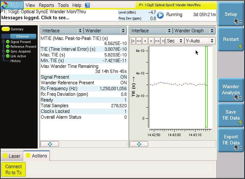
Best Practices for Testing Ethernet and Network Synchronization at the Cell Site

           Key Test Points
           In this deployment model, there are three key test points that network technicians and engineers need to access to ensure high-
           quality cell-site performance.

                                                                    Figure 2. Small-cell test points

           These test points, which are illustrated in Figure 2, are the Ethernet interface upstream of the CSR, the Ethernet interface downstream
           of the CSR, and the synthesized timing interface between the CSR and the small cell. Note that in some cell-site deployments, a CSR
           may not be present. In this case, test point 1 and test point 2 will be combined and the timing will be synthesized directly in the small
           cell. The test point for synthesized timing would then become an output reference of the eNodeB.

           Base Station Activation and Troubleshooting Workflows
           JDSU T-BERD/MTS-6000A MSAM and T-BERD/MTS-5800 handheld field-test instruments provide network technicians and
           engineers with several tools to prove high-quality eNodeB connectivity and timing synchronization. As illustrated in Figure 3,
           these tests can be grouped into basic and advanced Ethernet backhaul workflows. JDSU recommends performing the basic
           workflow on every eNodeB installation and the advanced workflow on a statistical sampling of eNodeB installations or when
           troubleshooting network timing-related problems. The tests in the basic workflow, which will be described in the following
           sections, lets mobile operators:
           •   Validate performance of the backhaul network from the eNodeB to the mobile switching center (MSC) to ensure correct
               configuration and high-quality data-plane and control-plane performance
           •   Test for the presence and correct configuration of network synchronization protocols to ensure that the CSR synthesizes a
               clock from the correct timing source

                                                           Figure 3. Basic and advanced mobility workflows

www.jdsu.com                                                                                                                                           3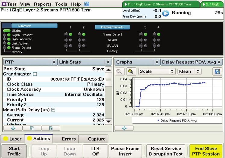
Best Practices for Testing Ethernet and Network Synchronization at the Cell Site

           The advanced workflow adds tests to measure the quality of the network synchronization protocols as well as the quality of
           synthesized reference clocks.
           The following topics describe the key tests that JDSU recommends at each of the three test points and notes whether each test is
           part of the basic or advanced workflow. Note that the applicability of each test for a given small-cell deployment will depend on
           the specific technologies used for that deployment.

           Test Point 1 — Upstream of the CSR
           The Ethernet link connected to the upstream of the CSR transports Ethernet traffic (both user as well as signaling traffic) and also
           provides the timing information that the CSR will use to synthesize the timing reference for the eNodeB. As such, there are several
           different kinds of tests that need to be performed at this test point to ensure high-quality cell-site operation. As illustrated in
           Figure 3, the basic Ethernet backhaul workflow at this test point includes:
           1. J-Proof Layer 2 control-plane transparency — ensures that Layer 2 control planes such as CDP, STP, and LAPD traverse the
              backhaul network to ensure proper communication between the CSR and network elements at the MSC.
           2. SyncE configuration — ensures that the Ethernet signal present at the test point is on frequency and has the expected timing
              quality.
           3. IEEE 1588v2 PTP configuration — verifies connectivity to a PTP grandmaster and ensures that packet delay variation on PTP
              packets is within the expected threshold.

                                                                Figure 4. Basic workflow at test point 1

           The advanced workflow at test point 1 consists of:
           1. Measuring wander on a synchronous Ethernet signal to ensure that the timing reference to the CSR is within the specified mask.
           2. Checking connectivity to a 1588v2 grandmaster and measuring PDV and iPDV on the PTP packets with greater accuracy as
              well as measuring the one-way delay to and from the PTP grandmaster to ensure that the upstream and downstream delays
              are symmetric and/or stable over time.

www.jdsu.com                                                                                                                                      4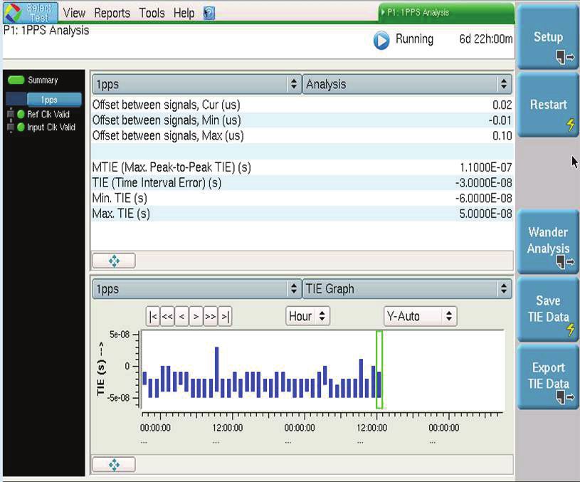
Best Practices for Testing Ethernet and Network Synchronization at the Cell Site

                                                              Figure 5. Advanced workflow at test point 1

           Test Point 2 — Downstream of the CSR
           The Ethernet interface downstream of the CSR connects the CSR to the eNodeB to transmit both user data and signaling
           information. The tests performed at this interface ensure robust connectivity and performance of the end-to-end connection
           from the eNodeB to the MSC. Specifically tests at this test point include:
           1. RFC 2544 or Y.1564 — validates end-to-end configuration at either the Ethernet or IP level (depending on the backhaul
              network specifics) to ensure that the key performance objectives such as CIR, CBS, latency, packet jitter, and frame loss are
              met. Network operators can select either RFC 2544 or Y.1564 to test a single service or select Y.1564 to test multiple classes of
              service.
           2. RFC 6349 TrueSpeedTM — tests end-to-end throughput using TCP traffic to ensure that the network provides the expected
              throughput without causing retransmissions that place additional strain on the limited wireless spectrum and cause poor
              end-user quality-of-experience.

                                                                Figure 6. Basic workflow at test point 2

www.jdsu.com                                                                                                                                      5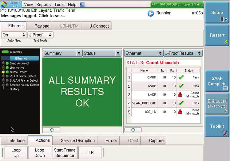
Best Practices for Testing Ethernet and Network Synchronization at the Cell Site

           Test Point 3 — Synthesized Timing Interface
           The eNodeB obtains its timing reference from the synthesized timing interface, which could be one of several signals such as 1
           PPS, E1, T1, 2 MHz, or 10 MHz. The accuracy and stability of this timing reference directly determines the accuracy of the frequency
           transmitted on the air interface. Poor accuracy on the air interface can lead to interference with neighboring cells and lead to
           dropped calls and poor data throughput. The key tests to perform are:
           1. Time offset and wander measurements on 1 PPS signals
           2. Wander measurements on E1, T1, 2 MHz, 10 MHz signals

                                                              Figure 7. Advanced workflow at test point 3

           Key Test Details
           This section provides detailed test information for:
           •   RFC 2544
           •   Y.1564
           •   J-Proof
           •   RFC 6349
           •   IEEE 1588v2 PTP Configuration
           •   IEEE 1588v2 PTP Advanced Test
           •   Synchronous Ethernet Configuration
           •   SyncE Wander
           •   1 PPS Analysis
           •   T1, E1, 2 MHz, 10 MHz Wander Analysis

www.jdsu.com                                                                                                                                      6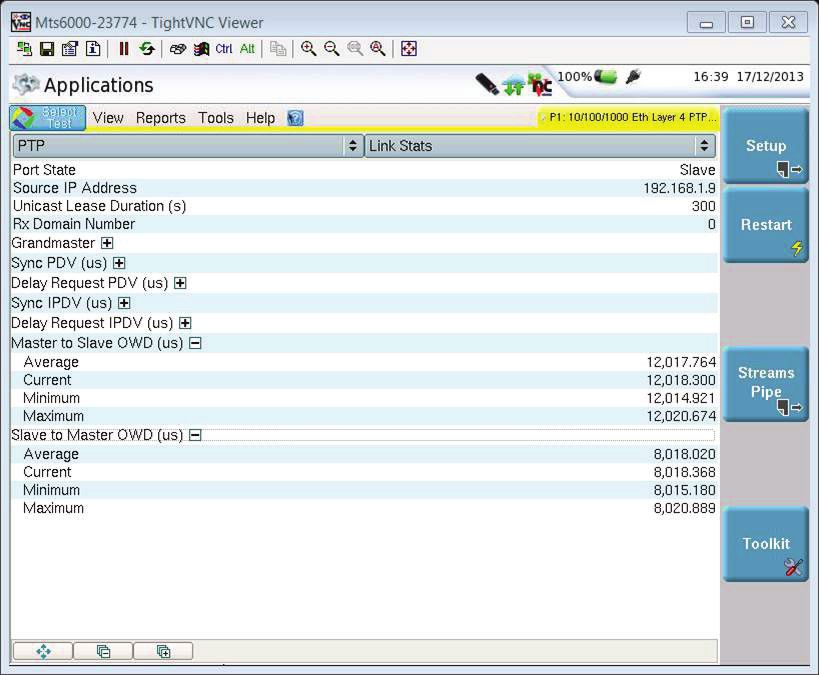
Best Practices for Testing Ethernet and Network Synchronization at the Cell Site

           RFC 2544

                                                                       Figure 8. RFC 2544 results

           What the test is: RFC 2544 is a widely-used test methodology to verify key performance indicators (KPIs) at the Ethernet or IP level
           for a single service of data traffic. The standard calls for measurements of throughput, latency, and frame loss. In addition to these,
           JDSU recommends that mobility operators also test for packet jitter and committed burst size (CBS).
           When to use it: RFC 2544 is the ideal test to ensure Layer 2 (Ethernet) or Layer 3 (IP) connectivity when only a single stream or
           single class of service (CoS) of traffic is present. A single stream could be defined as untagged Ethernet frames, a single Ethernet
           VLAN, or a single IP DSCP/TOS. Due to only supporting a single stream, it is simpler to configure and faster to run than Y.1564.
           What it measures:
           •   Throughput — the maximum sustained rate of Ethernet or IP traffic that can be passed through the network without frame loss.
           •   Latency —the average time that it takes for Ethernet frames or IP packets to traverse the network; latency can be measured
               either round trip or separately for each direction — upstream and downstream.
           •   Packet jitter —the average inter-frame delay variation over the course of the test per RFC 3550 Appendix A.8.
           •   Frame loss —the ratio of the number of frames lost to the number of frames transmitted over the course of the test.
           •   Committed burst size (CBS) — the configured number (the CBS parameter) of bytes of Ethernet frames that can be sent as a
               burst at line rate without frame loss.

www.jdsu.com                                                                                                                                         7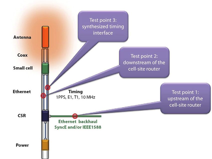
Best Practices for Testing Ethernet and Network Synchronization at the Cell Site

           Y.1564

                                                                Figure 9. Y.1564 SAMComplete results

           What the test is: Y.1564 is a more advanced test methodology for measuring Ethernet or IP KPIs that can be substituted for RFC
           2544 when the network supports multiple classes of service (CoS) such as multiple Ethernet VLANs or multiple IP DSCP/TOS
           values. The test methodology will first verify the configuration of each CoS separately and then verify performance with all CoS
           running simultaneously.
           When to use it: Y.1564 is ideally used when an Ethernet or IP network is configured to support multiple CoS and each CoS
           needs to be verified, such as ensuring that VoIP traffic or management-plane traffic is transported through the network with
           lower latency (frame delay) and jitter (inter-frame delay variation) than data traffic. The test verifies both bandwidth profile traffic
           parameters—committed information rate (CIR), excess information rate (EIR), and CBS—and service level agreement (SLA)
           performance objectives: frame delay (FD), frame loss ratio (FLR), and frame delay variation (FDV).
           What it measures:
           •   CIR — verifies that Ethernet frames can be passed through the network at the CIR and still meet SLA performance objectives.
           •   EIR — this optional parameter verifies that Ethernet fames can be passed through the network at a rate of CIR + EIR and still
               meet SLA performance objectives.
           •   CBS — the configured number (the CBS parameter) of bytes of Ethernet frames can be sent as a burst at line rate without
               frame loss.
           •   FD — the average time that it takes for Ethernet frames or IP packets to traverse the network; FD can be measured either
               round trip or separately for each direction: upstream and downstream.
           •   FLR — the ratio of the number of frames lost to the number of frames transmitted over the course of the test.
           •   FDV — the average inter-frame delay variation over the course of the test.

www.jdsu.com                                                                                                                                          8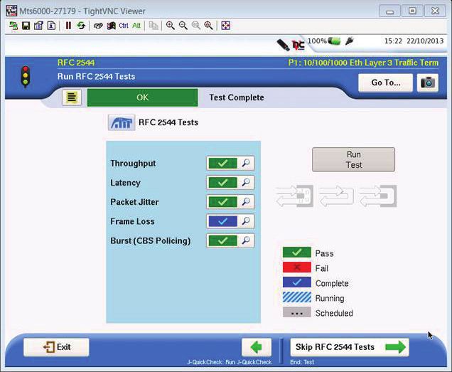
Best Practices for Testing Ethernet and Network Synchronization at the Cell Site

           J-Proof

                                                             Figure 10. J-Proof Layer 2 transparency results

           What it is: J-Proof is a Layer 2 control-plane (L2CP) transparency test that is designed to ensure that Layer 2 control-plane
           protocols such as Cisco discovery protocol (CDP), spanning tree protocol (STP), and generic attributes registration protocol
           (GARP) successfully traverse an Ethernet backhaul network. Ethernet backhaul networks typically encapsulate user and control-
           plane traffic so that it can be properly and transparently forwarded to the far end. A common network misconfiguration results
           in control-plane frames not being properly encapsulated and being processed by an intermediate switch or router so that the
           frames do not make it to the far end or are modified in transit. The J-Proof test ensures that all relevant control-plane frames
           successfully traverse the network. See MEF 6.1.1 for details on tunneling L2CP frames.
           When to use it: J-Proof is useful in situations when a mobile operator is using an Ethernet virtual private line service to backhaul
           traffic from a cell site to the MSC. In these cases, Layer 2 control-plane traffic from the CSR or eNodeB needs to successfully traverse
           the backhaul network so that it can be processed at the MSC.
           What it measures:
           •   Pass/fail indications for each L2CP protocol that successfully traverses the network.
           •   Indications of header error or payload errors for L2CP frames that return with errors.

www.jdsu.com                                                                                                                                          9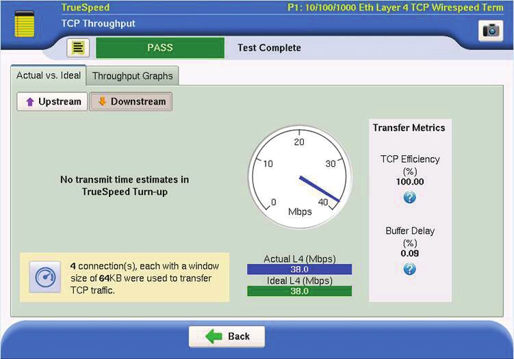
Best Practices for Testing Ethernet and Network Synchronization at the Cell Site

          RFC 6349

                                                        Figure 11. RFC 6349 TrueSpeed TCP throughput results

          What it is: RFC 6349 TrueSpeed is a test to measure TCP throughput in both the upstream and downstream directions. Measuring
          throughput at the TCP Layer is critical to ensuring a high-quality backhaul connection because data traffic generated from mobile
          devices predominantly uses TCP for e-mail, web browsing, and mobile application data transfer. TCP throughput (measured at
          Layer 4) can often be dramatically worse than Ethernet or IP throughput (measured at Layer 2 or 3) because packet loss, network
          congestion, or changing delay can cause TCP retransmissions. Passing RFC 6349 results ensure that mobile users will get the data
          throughput that they expect.
          When to use it: RFC 6349 is the industry standard for TCP throughput measurements. JDSU recommends mobile operators
          perform an RFC 6349 TrueSpeed test on all backhaul connections because mobile devices use TCP for so many data applications.
          What it measures:
          •   TCP throughput — the maximum rate that TCP traffic can traverse the network when taking any retransmissions into account;
              this measurement is compared with the ideal TCP throughput to generate a pass/fail result.
          •   TCP efficiency — an indication of how efficiently TCP connections work over the network by calculating the percentage
              of payload bytes that did not need to be retransmitted to the total number of bytes transmitted (transmissions plus
              retransmissions).
          •   Buffer delay percentage — the increase in TCP round trip time (RTT) over the course of the test; this measurement combined
              with the TCP efficiency metric can indicate if packet loss or network buffer congestion are contributing to poor TCP
              throughput.

www.jdsu.com                                                                                                                                  10
Best Practices for Testing Ethernet and Network Synchronization at the Cell Site
IEEE 1588v2 PTP Configuration
Figure 12. IEEE 1588v2 PTP configuration test results
What the test is: The IEEE 1588v2 configuration test is used to ensure proper connectivity from the cell site to the PTP master
clock by emulating a PTP slave device. In addition, the test measures KPIs for the PTP traffic such as PDV, IPDV, and round-trip
latency. This test can be run both with the PTP packets encapsulated in Ethernet frames (Layer 2 mode) or with the PTP packets
encapsulated in UDP segments (Layer 4 mode).
When to use it: When cell-site equipment uses IEEE 1588v2 PTP for network synchronization, the PTP configuration test is ideal
for ensuring that cell-site equipment using IEEE 1588v2 PTP will be able to connect to the PTP grandmaster properly.
What it measures:
• Connectivity to the PTP master — ensures proper connectivity from the cell site to the PTP master. Ensures proper
configuration of VLAN ID, Master IP Address, and PTP Domain parameters. The test also provides the PTP master’s advertised
ID, clock class, clock accuracy, and time source, and priority for comparison to the expected parameters.
• Mean path delay — delay from the master to slave and the slave to master for comparison to the expected delay; due to the
nature of the PTP protocol, in the PTP configuration test, this value is simply the round-trip delay divided by two. For one-way
delay measurements, see the IEEE 1588 PTP advanced test.
• Packet delay variation (PDV) — the variation in packet delay for the PTP sync and PTP delay request packets, which are
transmitted between the PTP master and the slave (test instrument). PTP sync packets are transmitted from the master to
slave and PTP delay request messages are transmitted from the slave to the master. Per Y.1540 and Y.1563, the reference
delay is set to the minimum delay measured and packets with larger delays represent delay variation. Average, current, and
maximum values are measured for comparison with expected values.
• Inter-packet delay variation — the difference in delay for two consecutive pairs of packets for both PTP sync and PTP delay
request packets per RFC 5481 Clause 4.1; current, average, minimum, and maximum values are measured for comparison to
expected values.
www.jdsu.com 11Best Practices for Testing Ethernet and Network Synchronization at the Cell Site
IEEE 1588v2 PTP Advanced Test
Figure 13. IEEE 1588v2 PTP advanced results
What it is: The PTP Advanced test adds additional capability to the basic IEEE 1588 test and is designed to troubleshoot network
delay asymmetries that have a negative impact on the IEEE1588v2 PTP protocol. The test utilizes a 1 PPS signal and time of day
information from a GPS receiver to take highly accurate one-way delay measurements from master to slave and from slave to
master. Network delay asymmetries are undetectable by the PTP protocol and are a common source of timing errors in PTP
deployments.
When to use it: For troubleshooting of problematic cell sites using IEEE 1588v2 PTP as a timing reference or as a proactive
statistical check on the quality of the network connection between PTP master and slave locations.
What it measures:
• All parameters listed in the basic 1588v2 PTP configuration test listed above with the exception of the mean path delay, which
is replaced with the one-way delay measurements listed below. In addition, PDV and IPDV values will have higher accuracy
due to the reference signal being a more accurate 1 PPS signal derived from a GPS receiver.
• Master to slave one-way delay (OWD) — the delay from the PTP master to the test instrument. This measurement is derived
by comparing the time stamp in the PTP sync message (the time the sync packet left the master) with the arrival time of the
packet at the test information (referenced to time of day from the GPS receiver).
• Slave to master OWD — the delay from the test instrument to the PTP master. This measurement is derived by comparing the
transmit time the PTP delay request message from the test instrument (referenced to time of day from the GPS receiver) with
the time stamp in the PTP delay response message (indicating the time the delay request message arrived at the master).
www.jdsu.com 12Best Practices for Testing Ethernet and Network Synchronization at the Cell Site
Synchronous Ethernet Configuration
Figure 14. SyncE configuration results
What the test is: The synchronous Ethernet (SyncE) configuration test ensures that the Ethernet connection provided to the cell
site is a valid SyncE signal. This is defined by the signal being on frequency and containing synch status messages (SSM) at the
expected rate and with the expected quality level.
When to use it: This test is appropriate when the cell-site equipment is using SyncE as a timing reference. It can be used both at
initial activation to quickly ensure a SyncE signal is present and for troubleshooting the cause of poor timing such as a degraded
quality level.
What it measures:
• Receive frequency and receive frequency deviation — the receive frequency relative to the highly accurate internal clock
source in the test instrument. Valid SyncE signals should have a maximum frequency deviation of not more than 4.6 ppm.
Current and maximum frequency deviations are measured.
• Synchronization status messages (SSM) — valid SyncE signals include periodic SSMs to indicate that the signal is a valid SyncE
signal and to indicate the quality level of the clock source used to derive the frequency of the signal. Either missing SSMs or a
mismatch between the expected quality level and the quality level in the SSM indicate a network misconfiguration that will
negatively impact the cell-site timing reference.
www.jdsu.com 13Best Practices for Testing Ethernet and Network Synchronization at the Cell Site
SyncE Wander
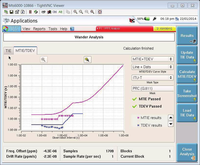
Figure 15. SyncE wander analysis results
What the test is: The SyncE wander test is used to measure the quality of the SyncE signal that is being used to generate network
synchronization at the cell site. The test measures the timing error on the SyncE signal under test relative to a 2 MHz or 10 MHz
timing reference that is often provided by a portable GPS receiver or a high-stability frequency reference. This test provides an
indication of whether the SyncE signal used as a timing source for the cell site is of a high-enough quality to support the wireless
protocol.
When to use it: For troubleshooting problematic cell sites using synchronous Ethernet as a timing reference or as a proactive
statistical check on the quality of the synchronous Ethernet signal at select base-station locations.
What it measures:
• Receive frequency and receive frequency deviation — the receive frequency relative to the highly-accurate internal clock
source in the test instrument. Valid SyncE signals should have a maximum frequency deviation of not more than 4.6 ppm.
Current and maximum frequency deviations are measured.
• Time interval error (TIE) — the time error between the SyncE signal under test and the reference signal. The TIE data, which is
directly measured by the instrument, is used to calculate MTIE and time deviation (TDEV) parameters.
• Maximum time interval error (MTIE) — calculated as the maximum peak-to-peak TIE for a given observation time. It is typically
graphed for a range of observation times and compared to a specified MTIE mask to generate a pass/fail result.
• TDEV — a calculated measure of the expected time variation for a given observation time. It is typically graphed for a range of
observation times and compared to a specified TDEV mask to generate a pass/fail result.
MTIE and TDEV analysis and pass/fail results are similar to Figure 17.
www.jdsu.com 14Best Practices for Testing Ethernet and Network Synchronization at the Cell Site
1 PPS Analysis
Figure 16. 1 PPS analysis results
What the test is: The 1 PPS analysis test measures the accuracy of a 1 PPS signal (often derived from an IEEE 1588v2 PTP source)
relative to a 1 PPS reference signal, which is often sourced from a portable GPS receiver. This test provides an indication on
whether the 1 PPS used as a timing source for the eNodeB is of a high-enough quality to support the wireless protocol.
When to use it: This test is used when the eNodeB requires a 1 PPS clock input (LTE-TDD air interfaces for example). Comparing
the results of this test to the clock input specifications on the eNodeB will indicate whether the eNodeB will be able to conform to
standards for the particular air interface.
What it measures:
• Offset between signals — the time offset between the 1 PPS signal under test and the reference signal measured in
microseconds. This measurement indicates how much timing error is present on the signal under test. Current, minimum, and
maximum values are measured.
• TIE — the time error between the 1 PPS signal under test and the reference signal. The TIE data, which is directly measured by
the instrument, is used to calculate MTIE and TDEV parameters.
• MTIE — the maximum peak-to-peak TIE for a given observation time. It is typically graphed for a range of observation times
and compared to a specified MTIE mask to generate a pass/fail result.
• TDEV — a calculated measure of the expected time variation for a given observation time. It is typically graphed for a range of
observation times and compared to a specified TDEV mask to generate a pass/fail result.
www.jdsu.com 15Best Practices for Testing Ethernet and Network Synchronization at the Cell Site
T1, E1, 2 MHz, 10 MHz Wander Analysis
Figure 17. T1, E1, 2 MHz, and 10 MHz wander analysis results
What the test is: The wander analysis test for T1, E1, 2 MHz, and 10 MHz signals measures the accuracy of one of those signals
(often derived from an IEEE 1588v2 PTP source) relative to a 2 MHz or 10 MHz reference signal, which is often sourced from a
portable GPS receiver. This test provides an indication on whether the signal used as a timing source for the eNodeB is of a high-
enough quality to support the wireless protocol.
When to use it: The appropriate wander analysis test is used when the eNodeB requires a T1, E1, 2 MHz or 10 MHz clock input
(LTE-FDD air interfaces for example). Comparing the results of this test to the clock input specifications on the eNodeB will
indicate whether the eNodeB will be able to conform to standards for the particular air interface.
What it measures:
• TIE — the time error between the signal under test and the reference signal. The TIE data, which is directly measured by the
instrument, is used to calculate MTIE and TDEV parameters.
• MTIE — the maximum peak-to-peak TIE for a given observation time. It is typically graphed for a range of observation times
and compared to a specified MTIE mask to generate a pass/fail result.
• TDEV — a calculated measure of the expected time variation for a given observation time. It is typically graphed for a range of
observation times and compared to a specified TDEV mask to generate a pass/fail result.
North America Toll Free: 1 855 ASK-JDSU (1 855 275-5378)
Latin America Tel: +1 954 688 5660 Fax: +1 954 345 4668
Asia Pacific Tel: +852 2892 0990 Fax: +852 2892 0770
EMEA Tel: +49 7121 86 2222 Fax: +49 7121 86 1222
www.jdsu.com/nse © 2014 JDS Uniphase Corporation Product specifications and descriptions in this document subject to change without notice.
30175853 000 0314 ETHERNET-NETSYNC.AN.TFS.AE March 2014You can also read