All About the Acronyms: RJ, DJ, DDJ, ISI, DCD, PJ, SJ
←
→
Page content transcription
If your browser does not render page correctly, please read the page content below
Jitter 360° Knowledge Series
                                        Part 3: All About the Acronyms

                 All About the Acronyms: RJ, DJ, DDJ, ISI, DCD, PJ, SJ, …
                                        Ransom Stephens, Ph.D.

Abstract:

        Jitter analysis is yet another field of engineering that is pock-marked with acronyms. Each
        category and type of jitter has its own acronym and every one of them gives insight into
        problems that limit the bit error ratio of a system. In this paper, we define the categories
        and types of jitter, their origins and interrelationships, and how they can be used to
        diagnose and debug system hardware.

Acronyms seem like convenient abbreviations once we know them, but prior to that, they’re a closed
language that can feel like no more than a bunch of obfuscating terms when used by others. Of course,
when we use them, acronyms are simply shorthand that “everyone knows.” In this paper we err in the
opposite direction. Rather than annoy you by using too many acronyms, I’m going to annoy you by
spelling out every acronym almost every time I use it.

Understanding a system usually consists of separating it into simple bite-sized pieces which combine to
form an arbitrarily complex system. The same is true of jitter analysis. If we’re given a system whose Total
Jitter at a Bit Error Ratio of 10-12, i.e., TJ(BER) = TJ(10-12), is larger than allowed by a product requirement
or standard specification, it doesn’t tell us anything about how to fix the problem [For a review of TJ(BER),
see the first installment in this series, Part I: The Meaning of Total Jitter]. We need to re-categorize,
analyze, and sort the system into successively more simple pieces, hence the acronyms.

The jitter “Family Tree,” Figure 1, shows one way to categorize different types of jitter. The first branch
separates Random (RJ) and Deterministic Jitter (DJ). The second branch splinters Deterministic Jitter
(DJ) into Data-Dependent Jitter (DDJ), Periodic Jitter (PJ), and Bounded Uncorrelated Jitter (BUJ). The
primary source of Data-Dependent Jitter (DDJ) is Inter-Symbol Interference (ISI), but the amount of ISI is
affected by the level of Duty-Cycle Distortion (DCD) – hence the dotted line connecting DCD and ISI.
Some people put Duty Cycle Distortion (DCD) under Data-Dependent Jitter (DDJ) because of the affect
DCD has on Inter-Symbol Interference (ISI). I chose to put Duty-Cycle Distortion (DCD) under Periodic
Jitter (PJ) – after all, DCD is an asymmetry in the clocking of logic transitions. Periodic Jitter (PJ) is on the
uncorrelated side of the diagram. The terms “correlated” and “uncorrelated” in the diagram indicate

                                                   1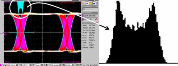
Jitter 360° Knowledge Series
                                        Part 3: All About the Acronyms

whether the amplitude of jitter changes with different transmitted data signals or data rates, that is,
whether or not the jitter amplitude is “correlated to the data.” Generally Periodic Jitter (PJ) is uncorrelated,
but Duty-Cycle Distortion (DCD) is a type of PJ that is correlated, so it’s on that side of the diagram.
Sinusoidal Jitter (SJ) is the simplest type of Periodic Jitter (PJ) and is rarely correlated to the data.

There are many different ways that jitter can be categorized in a diagram like that in Figure 1. The
important thing is not how we draw such a figure, but that we recognize the components, understand their
causes, and appreciate whether or not one component can affect another.

Figure 1: The jitter “Family Tree.”

In the following sections we’ll go through each type of jitter and sort out some of the different ways that
jitter is categorized.

Random Jitter – RJ
As described in the first installment of this series, The Meaning of Total Jitter, Random Jitter (RJ) is
caused by the combination of a huge number of sources, each of very small magnitude. According to the
Central Limit Theorem, RJ should follow a Gaussian distribution, Figure 2.

                                                   2
Jitter 360° Knowledge Series
Part 3: All About the Acronyms
Figure 2: Random Jitter (RJ) follows a Gaussian distribution.
RJ is primarily caused by thermal processes, microscopic variations in the resistance and impedance of
circuit traces which can be caused by the inevitable small variations of trace width, dielectric properties
such as asymmetries in the weave of FR-4, and many other microscopic effects that are statistically
impossible to isolate.
Since RJ follows an unbounded distribution it is quantified by the width, or standard deviation, σ, of its
distribution.
• RJ is unbounded – there is a finite probability that random effects could cause a logic transition to
appear anywhere, though, of course, the probability of an extremely large amount of RJ on a
given transition is increasingly small. For example, the probability of RJ causing jitter greater than
seven times the standard deviation of its distribution is one in a trillion.
3Jitter 360° Knowledge Series
Part 3: All About the Acronyms
• RJ is uncorrelated to the data – the amount of RJ on a given transition is not related to the
transmitted data signal or data rate.
• RJ is aperiodic – RJ is random in nature and doesn’t occur with any predictable regularity.
• RJ is independent of the other sources of jitter in the sense that changing RJ has no effect on the
magnitudes of other types of jitter.
Deterministic Jitter – DJ
Deterministic Jitter (DJ) is the jitter that remains after Random Jitter (RJ) has been removed. In principle,
though almost never in practice, DJ can be calculated from a complete understanding of the circuit and its
environment. Since DJ can be composed of all the other types of jitter, it doesn’t follow a given
distribution function the way that Random Jitter (RJ) follows a Gaussian. On the other hand, since DJ is
composed of a finite number of deterministic processes its distribution is bounded.
We usually characterize DJ by either its peak-to-peak value, DJ(p-p), or a model dependent version of the
peak-to-peak value that is derived from the remarkably convenient dual-Dirac model, DJ(δδ) – which is
described in the second part in this series, The Dual-Dirac Model, What it is and What it is Not.
Problems caused by DJ can be diagnosed by further resolving it into its constituents.
• DJ is bounded but doesn’t follow a general distribution function.
• DJ may include both periodic and aperiodic components that may or may not depend on the
transmitted data signal. That is, the DJ of a given logic transition may or may not affect the jitter of
another transition.
Duty-Cycle Distortion – DCD
Duty-Cycle Distortion (DCD) is a measure of the asymmetry in the duty cycle of the transmitter. In Figure
3, the one in the sequence 00001000 is of a different width than the zero in 11110111 – the duty-cycle is
distorted. Another manifestation of DCD is the difference in the rise and fall times of a signal resulting in a
fixed time displacement of the rising and falling edges. In either case, in the absence of Inter-Symbol
Interference (ISI), DCD follows a simple bimodal distribution. Equivalently, the amplitude of DCD is given
by the difference of the average positions of rising and falling edges.
DCD is usually caused by an asymmetry in either the clock signal driving the transmitter or in a limiting
amplifier within the transmitter.
4Jitter 360° Knowledge Series
Part 3: All About the Acronyms
Figure 3: Simple example of Inter-symbol interference.
DCD is correlated with Inter-Symbol Interference (ISI) in the sense that changing ISI can result in a
change in DCD, and vice versa. Another way to think of the correlation is in the sense of interference;
DCD and ISI interfere with each other. Because of this correlation or interference, DCD is sometimes
categorized with Inter-Symbol Interference (ISI) under Data-Dependent Jitter (DDJ). In a system with no
Inter-Symbol Interference (ISI), the level of DCD is explicitly independent of the transmitted data signal
and so is not really “data-dependent.”
• DCD is bounded
• DCD follows a simple bimodal distribution
• DCD is usually caused by a clock asymmetry or limiting amplifier imperfection and so is periodic
at the data-rate
• DCD is correlated with Inter-Symbol Interference (ISI) – a change in DCD causes a change in ISI
and vice versa
Data-Dependent Jitter – DDJ
Data-Dependent Jitter (DDJ) encompasses all jitter whose magnitude is affected by the transmitted data
signal. For example, as illustrated in Figure 4, when the jitter of a 0 Æ 1 transition that follows a sequence
of alternating bits, e.g., 01010101, differs from a 0 Æ 1 transition that follows a long string of identical bits,
e.g., 00000001, that jitter is called data-dependent.
DDJ is caused primarily by a combination of macroscopic impedance mismatches, the resistance and
frequency response of the transmission path, and asymmetries in the rising and falling edges of the
transmitted signal. DDJ is usually associated with Inter-Symbol Interference (ISI) but is affected by Duty-
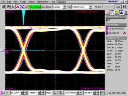
Cycle Distortion (DCD). The result, as shown in Figure 5, is a waveform that differs significantly from the
ideal.
5Jitter 360° Knowledge Series
Part 3: All About the Acronyms
Figure 4: Example waveform of simple Data-Dependent Jitter (DDJ).
Generally two random variables are correlated if changing one of the variables causes the other to
change. Correlation is an important concept which appears in two separate contexts in jitter analysis.
First, as already described, jitter is said to be correlated to the data if the amplitude of jitter is affected by
the transmitted data signal or the data rate. Second, the primary source of DDJ, Inter-Symbol Interference
(ISI) is correlated to, or interferes with, Duty-Cycle Distortion (DCD) – a change in the ISI of a signal
changes the DCD of that signal and vice-versa.
DDJ is a type of “correlated jitter” by virtue of its dependence on the transmitted data signal.
Figure 5: Data-dependent jitter and eye diagram.
• DDJ follows a distribution that can’t be described by any single global distribution function
• DDJ is also known as “correlated jitter” because data-dependent is equivalent to “correlated to
the transmitted data signal”
Inter-Symbol Interference – ISI
Inter-Symbol Interference (ISI) is the primary cause of Data-Dependent Jitter (DDJ). The situation is
complicated by the correlation of ISI and Duty-Cycle Distortion (DCD).
6Jitter 360° Knowledge Series
Part 3: All About the Acronyms
ISI is caused by a combination of the design of the trace and circuit geometry, the media composing both
the conductor and dielectric of the circuit, and the waveform of the transmitted signal. In much of the
literature, the design of the transmitter itself, including package design, is neglected as a source of ISI. It
is important to keep in mind that the ISI of the transmitted waveform can interfere with the ISI introduced
by the transmission path. A lot of confusion erupts from comparison of ISI measurements on a given
cable but with different transmitters.
Figure 6: Simple example of Inter-Symbol Interference (ISI). VThreshold is the logic-decision
threshold, if the observed voltage is greater than VThreshold then the bit is identified as a 1, if less
than VThreshold, a 0.
A good example of ISI is the modification of the pulse-shape of different bits in a signal as they traverse a
transmission line. Transmission lines at data rates above about 100 MHz are better thought of as
complicated waveguides in a dielectric medium. The resistance of the conducting traces cause signal
attenuation and the frequency-dependence of the dielectric medium causes non-uniform frequency
response. The non-uniform frequency response subjects the signal to a filtering effect. The dominant
frequency component of a given bit is determined by the identity of the bits that surround it. Consider the
data sequences shown in Figure 6 where a simple Resistor-Capacitor (RC) time constant is used to
illustrate ISI. In Figure 6a, the data signal, 01010101, is a clock signal at half the data rate. The response
of the circuit to the transmitted data signal is sufficient for each bit to cross the logic-decision voltage
threshold and be accurately identified. In Figure 6b, the data signal, 00001111 is a clock signal at one-
eighth the data rate. Over the string of Consecutive Identical Bits (CIB or CID) the time constant is
sufficiently short for the signal to reach the voltage rail but, in so doing, does not permit enough time for
the signal to cross the voltage threshold during the first logic 1 following the string of 0s. In fact, the
00001111 string would be identified as 10000111. A mixed example is shown in Figure 6c; here the
00001011 signal would be identified as 10000001.
7Jitter 360° Knowledge Series
Part 3: All About the Acronyms
Now combine the unavoidable non-uniform frequency response of the dielectric, like Flame Retardant
Type-4 (FR-4), with the interference of signals from discrete impedance mismatches that cause multiple
reflections and multiple paths from input to output and you can see how ISI can cause complex problems,
Figure 7. The result is that the waveform of any bit in a data signal can differ depending on the number of
Consecutive Identical Bits (CIB or CID) preceding it. Data coding, for example 8b10b coding, is used in
many technologies, e.g., PCI Express, to prevent the occurrence of long strings of Consecutive Identical
Bits (CIB or CID). An important feature of ISI is that it affects both the amplitude and timing of the signal.
In other words, it is a source of amplitude noise as well as jitter.
Figure 7: A signal with a great deal of Inter-Symbol Interference (ISI).
It is difficult to combine the ISI introduced by different circuit elements. For example if the transmitted
signal has a given level of ISI, then the ISI introduced by the transmission path will be different than if the
transmitted signal had no ISI. In other words, the ISI of consecutive circuit elements interferes with one
another – it is correlated.
ISI provides a good example of what it means to be “deterministic.” Time Domain Reflectometry (TDR)
can be used to measure the frequency and attenuation characteristics of a circuit resulting in the impulse
response as represented, for example, in the Scattering parameters (S-parameters), from which the
circuit’s transfer function can be calculated. The transfer function can then be applied to any data
sequence to yield the ISI waveform. That is, the transfer function is the complete understanding of the
circuit and its environment and, with it, we can predict the jitter of any given logic transition – exactly what
is meant by deterministic jitter. Due to its predictable nature, it is possible to correct ISI at the receiver
using equalization techniques.
There are two types of diagnostic techniques that can be used to reduce ISI. First, before a circuit is even
built, the ISI of different designs can be compared by calculating the Scattering parameters (S-
8Jitter 360° Knowledge Series
Part 3: All About the Acronyms
parameters) in a simulation. Second, Time Domain Reflectometry (TDR) can be used to locate discrete
impedance mismatches like those often found at vias and connectors.
• ISI is bounded
• ISI is only periodic if the signal is a repeating pattern
• ISI is caused by the geometry and media of the conductor and dielectric
• ISI is also caused by discrete impedance mismatches like those found at vias and connectors
which result in multiple reflections
• ISI can be introduced by the transmitter
• ISI of different circuit elements are correlated to each other – they interfere
• ISI can be predicted from the impulse response, such as can be derived from the Scattering
parameters (S-parameters) as measured through Time Domain Reflectometry (TDR)
Periodic Jitter – PJ
Periodic Jitter (PJ) includes any jitter at a fixed frequency or period. PJ is ultimately an example of
periodic phase modulation and may be the most useful category of jitter. It’s easy to measure accurately
and appears in the jitter-frequency spectrum as distinct peaks. The jitter-frequency is the offset frequency
of the jitter with respect to the data rate. When a PJ peak is identified it can usually be associated with a
noisy circuit element operating at that same frequency. The classic example is power supply feed-
through, but PJ can also be caused by crosstalk from neighboring data lines or any other type of
Electromagnetic Interference (EMI).
PJ is always bounded and may have components that are correlated to the data, such as Duty-Cycle
Distortion (DCD).
• PJ can have a variety of wave shapes (e.g., square-wave phase modulation is PJ that results in a
dual-Dirac distribution) with corresponding jitter-frequency spectra
• PJ is bounded and follows a distribution that can be calculated if the amplitudes, frequencies, and
relative phases of all harmonics and PJ sources are measured
• PJ is easy to measure accurately
• PJ is useful in diagnosing jitter problems
9Jitter 360° Knowledge Series
Part 3: All About the Acronyms
Sinusoidal Jitter – SJ
Sinusoidal Jitter (SJ) is Periodic Jitter (PJ) at just one frequency. A tremendous amount of work has been
done in SONET/SDH jitter analyses to precisely calibrate jitter analyzers by applying SJ of known
frequency and amplitude and using the classic Bessel null technique.
In the time domain, SJ follows an easily identifiable “suspension bridge” structure as shown in Figure 8.
Figure 8: Sinusoidal jitter.
• SJ is Periodic Jitter (PJ) at just one frequency
• SJ is bounded and uncorrelated to the data
• SJ is easy to measure accurately
• SJ can be applied to a signal for use in calibrating test equipment
Bounded Uncorrelated Jitter – BUJ
Bounded Uncorrelated Jitter (BUJ) is a category used by most of the industry for organizing ignorance.
That is, most of the literature uses BUJ to represent all the types of jitter that we don’t know how to
measure. We assume that the only unbounded jitter is Random Jitter (RJ), by implication BUJ is
deterministic.
The two most debated flavors of BUJ are non-stationary jitter and the jitter-effects of crosstalk. Non-
stationary jitter is sporadic – neither periodic nor data-dependent – over the possible measurement time
scales. A good example is the state-dependent jitter of complex gate arrays where certain data patterns
10Jitter 360° Knowledge Series
Part 3: All About the Acronyms
present a repeatable, but rare, switching transient. Crosstalk presents a more challenging problem for
jitter analysis, one where the distinction between amplitude noise and timing jitter can’t be neglected.
Strictly speaking the most easily measured type of jitter, Periodic Jitter (PJ), is both bounded and
uncorrelated and so could accurately be categorized as BUJ. One manufacturer of test equipment uses
the acronym BUJ for Periodic Jitter (PJ). It is semantically accurate, but inconsistent with the vast majority
of jitter literature, an unfortunate choice that has caused a lot of confusion.
• BUJ bounded and uncorrelated to the data
• BUJ is usually used as a receptacle for the jitter we can’t measure
• The two most commonly discussed sources of BUJ are non-stationary jitter and the jitter effects
of crosstalk
Conclusion
There are many ways to categorize jitter. The most common criteria are:
• Random Jitter (RJ) vs Deterministic Jitter (DJ) which is equivalent to unbounded vs bounded
• correlated vs uncorrelated
• data-dependent vs data-independent
• periodic vs aperiodic
There is room to argue about whether some types of jitter, like Duty-Cycle Distortion (DCD), should be
categorized the way they I did here, but these arguments distract from the important issues. Namely, how
measurements of the different types of jitter can be used to reduce the Bit Error Ratio (BER) of a system.
11Jitter 360° Knowledge Series
Part 3: All About the Acronyms
bounded/ correlated/ periodic/
acronym Example cause
unbounded uncorrelated aperiodic
Random
RJ Unbounded Uncorrelated Aperiodic Thermal noise
Jitter
Deterministic
DJ Bounded Either Either Inter-Symbol Interference
Jitter
Periodic
PJ Bounded Either Periodic Power supply feed-through
Jitter
Sinusoidal
SJ Bounded Uncorrelated Periodic Electromagnetic interference
Jitter
Data-
Dependent DDJ Bounded Correlated Aperiodic Impedance mismatch
Jitter
Duty-Cycle
DCD Bounded Correlated Periodic Clock asymmetry
Distortion
Non-uniform frequency
Inter-Symbol
ISI Bounded Correlated Aperiodic response of a transmission
Interference
line
Bounded
Uncorrelated BUJ Bounded Uncorrelated Aperiodic Crosstalk
Jitter
Table 1: Summary of jitter acronyms.
12 55W-21989-0You can also read