Introduction to the Helicopter
←
→
Page content transcription
If your browser does not render page correctly, please read the page content below
Chapter 1

Introduction to the Helicopter
Introduction
A helicopter is an aircraft that is lifted and propelled by one
or more horizontal rotors, each rotor consisting of two or
more rotor blades. Helicopters are classified as rotorcraft
or rotary-wing aircraft to distinguish them from fixed-wing
aircraft because the helicopter derives its source of lift from
the rotor blades rotating around a mast. The word “helicopter”
is adapted from the French hélicoptère, coined by Gustave de
Ponton d’Amécourt in 1861. It is linked to the Greek words
helix/helikos (“spiral” or “turning”) and pteron (“wing”).

                                                                  1-1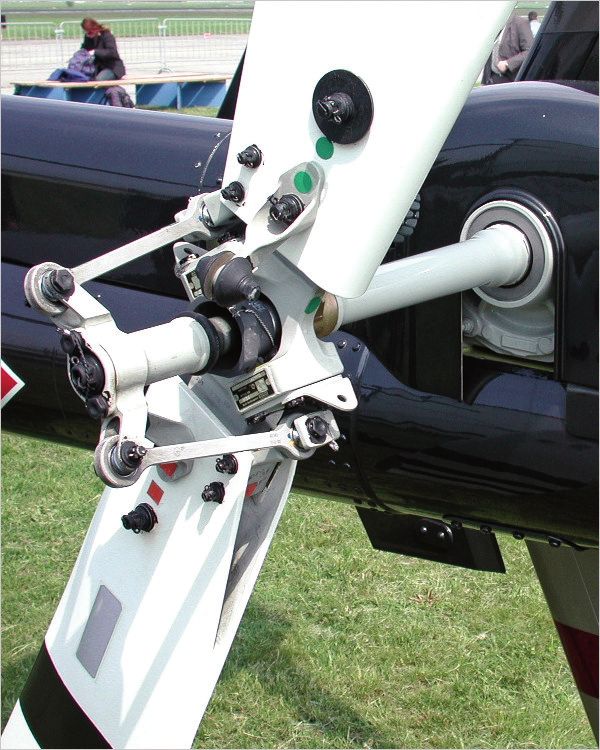
As an aircraft, the primary advantages of the helicopter are due
to the rotor blades that revolve through the air, providing lift
without requiring the aircraft to move forward. This creates
the ability of the helicopter to take off and land vertically
without the need for runways. For this reason, helicopters are
often used in congested or isolated areas where fixed-wing
aircraft are not able to take off or land. The lift from the rotor
also allows the helicopter to hover in one area and to do so
more efficiently than other forms of vertical takeoff and
landing aircraft, allowing it to accomplish tasks that fixed-
wing aircraft are unable to perform. [Figures 1-1 and 1-2]
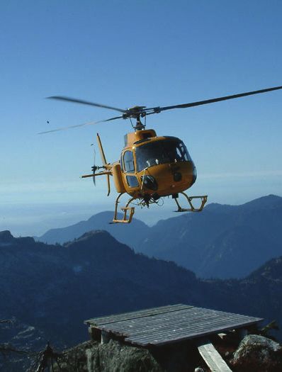
Figure 1-2. Search and rescue helicopter landing in a confined area.
main rotor, it was the single main rotor with an antitorque tail
rotor configuration design that would come to be recognized
worldwide as the helicopter.
Turbine Age
In 1951, at the urging of his contacts at the Department of
the Navy, Charles H. Kaman modified his K-225 helicopter
with a new kind of engine, the turbo-shaft engine. This
adaptation of the turbine engine provided a large amount of
horsepower to the helicopter with a lower weight penalty
than piston engines, heavy engine blocks, and auxiliary
components. On December 11, 1951, the K-225 became
the first turbine-powered helicopter in the world. Two years
later, on March 26, 1954, a modified Navy HTK‑1, another
Kaman helicopter, became the first twin-turbine helicopter
to fly. However, it was the Sud Aviation Alouette II that
would become the first helicopter to be produced with a
turbine engine.
Reliable helicopters capable of stable hover flight were
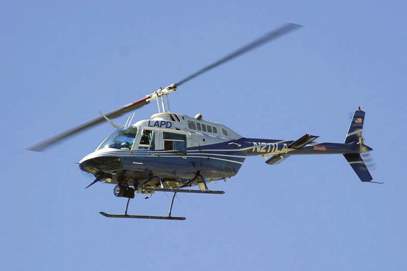
Figure 1-1. Search and rescue helicopter conducting a pinnacle
developed decades after fixed-wing aircraft. This is largely
approach.
due to higher engine power density requirements than fixed-
wing aircraft. Improvements in fuels and engines during
Piloting a helicopter requires a great deal of training and skill, the first half of the 20th century were a critical factor in
as well as continuous attention to the machine. The pilot must helicopter development. The availability of lightweight
think in three dimensions and must use both arms and both turbo-shaft engines in the second half of the 20th century led
legs constantly to keep the helicopter in the air. Coordination, to the development of larger, faster, and higher-performance
control touch, and timing are all used simultaneously when helicopters. The turbine engine has the following advantages
flying a helicopter. over a reciprocating engine: less vibration, increased
aircraft performance, reliability, and ease of operation.
Although helicopters were developed and built during the While smaller and less expensive helicopters still use piston
first half-century of flight, some even reaching limited engines, turboshaft engines are the preferred powerplant for
production; it was not until 1942 that a helicopter designed by helicopters today.
Igor Sikorsky reached full-scale production, with 131 aircraft
built. Even though most previous designs used more than one
1-2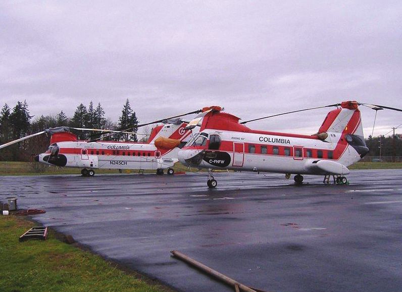
Uses                                                                   Rotor System
Due to the unique operating characteristics of the helicopter—         The helicopter rotor system is the rotating part of a
its ability to take off and land vertically, to hover for extended     helicopter that generates lift. A rotor system may be mounted
periods of time, and the aircraft’s handling properties under          horizontally, as main rotors are, providing lift vertically; it
low airspeed conditions—it has been chosen to conduct tasks            may be mounted vertically, such as a tail rotor, to provide
that were previously not possible with other aircraft or were          lift horizontally as thrust to counteract torque effect. In the
too time- or work-intensive to accomplish on the ground.               case of tilt rotors, the rotor is mounted on a nacelle that
Today, helicopters are used for transportation, construction,          rotates at the edge of the wing to transition the rotor from a
firefighting, search and rescue, and a variety of other jobs           horizontal mounted position, providing lift horizontally as
that require its special capabilities. [Figure 1-3]                    thrust, to a vertical mounted position providing lift exactly
                                                                       as a helicopter.

                                                                       Tandem rotor (sometimes referred to as dual rotor)
                                                                       helicopters have two large horizontal rotor assemblies; a twin
                                                                       rotor system, instead of one main assembly and a smaller
                                                                       tail rotor. [Figure 1-4] Single rotor helicopters need a tail
                                                                       rotor to neutralize the twisting momentum produced by the
                                                                       single large rotor. Tandem rotor helicopters, however, use
                                                                       counter-rotating rotors, with each canceling out the other’s
                                                                       torque. Counter-rotating rotor blades won’t collide with and
                                                                       destroy each other if they flex into the other rotor’s pathway.
                                                                       This configuration also has the advantage of being able to
                                                                       hold more weight with shorter blades, since there are two
                                                                       sets. Also, all of the power from the engines can be used for
                                                                       lift, whereas a single rotor helicopter uses power to counter
                                                                       the torque. Because of this, tandem helicopters are among
                                                                       some of the most powerful and fastest.

                                                                       Figure 1-4. Tandem rotor helicopters.

                                                                       Coaxial rotors are a pair of rotors turning in opposite
                                                                       directions, but mounted on a mast, with the same axis of
                                                                       rotation, one above the other. This configuration is a noted
                                                                       feature of helicopters produced by the Russian Kamov
Figure 1-3. The many uses for a helicopter include search and rescue   helicopter design bureau. [Figure 1-5]
(top), firefighting (middle), and construction (bottom).

                                                                                                                                  1-3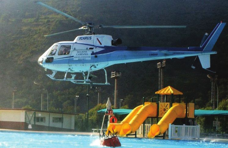
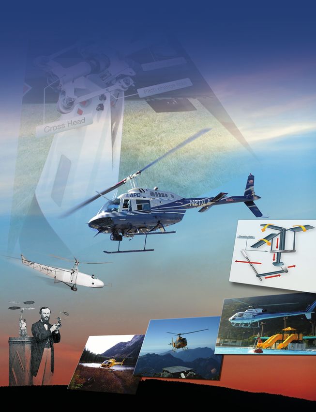
Hub

                                                                                 Mast                           Rotor blades

Figure 1-5. Coaxial rotors.                                         Figure 1-7. Basic components of the rotor system.

Intermeshing rotors on a helicopter are a set of two rotors         classified according to how the main rotor blades are attached
turning in opposite directions, with each rotor mast mounted        and move relative to the main rotor hub. There are three basic
on the helicopter with a slight angle to the other so that          classifications: semirigid, rigid, or fully articulated, although
the blades intermesh without colliding. [Figure 1-6] The            some modern rotor systems use an engineered combination
arrangement allows the helicopter to function without the           of these types. All three rotor systems are discussed with
need for a tail rotor. This configuration is sometimes referred     greater detail in Chapter 5, Helicopter Systems.
to as a synchropter. The arrangement was developed in
Germany for a small anti-submarine warfare helicopter, the          With a single main rotor helicopter, the creation of torque as
Flettner Fl 282 Kolibri. During the Cold War the American           the engine turns the rotor creates a torque effect that causes
Kaman Aircraft company produced the HH-43 Huskie, for               the body of the helicopter to turn in the opposite direction of
USAF firefighting purposes. Intermeshing rotored helicopters        the rotor (Newton’s Third Law: Every action has an equal
have high stability and powerful lifting capability. The latest     and opposite reaction, as explained in Chapter 2, General
Kaman K-MAX model is a dedicated sky crane design used              Aerodynamics). To eliminate this effect, some sort of
for construction work.                                              antitorque control must be used with a sufficient margin of
                                                                    power available to allow the helicopter to maintain its heading
                                                                    and prevent the aircraft from moving unsteadily. The three
                                                                    most common controls used today are the traditional tail
                                                                    rotor, Fenestron (also called a fantail), and the NOTAR®.
                                                                    All three antitorque designs will be discussed in chapter 5.

                                                                    Rotor Configurations
                                                                    Most helicopters have a single, main rotor but require a
                                                                    separate rotor to overcome torque which is a turning or
                                                                    twisting force. This is accomplished through a variable
                                                                    pitch, antitorque rotor or tail rotor. This is the design that
                                                                    Igor Sikorsky settled on for his VS-300 helicopter shown
                                                                    in Figure 1-8. It has become the recognized convention for
                                                                    helicopter design, although designs do vary. When viewed
                                                                    from above, designs from Germany, United Kingdom, and
Figure 1-6. HH-43 Huskie with intermeshing rotors.                  the United States are said to rotate counter-clockwise, all
                                                                    others are said to rotate clockwise. This can make it difficult
The rotor consists of a mast, hub, and rotor blades. [Figure 1-7]   when discussing aerodynamic effects on the main rotor
The mast is a hollow cylindrical metal shaft which extends          between different designs, since the effects may manifest on
upwards from and is driven by the transmission. At the              opposite sides of each aircraft. Throughout this handbook,
top of the mast is the attachment point for the rotor blades        all examples are based on a counter-clockwise rotating main
called the hub. The rotor blades are then attached to the hub       rotor system.
by a number of different methods. Main rotor systems are

1-4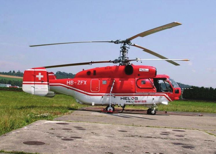
at the end of the tail boom provides an angled drive for the tail
                                                                     rotor and may also include gearing to adjust the output to the
                                                                     optimum rotational speed typically measured in revolutions
                                                                     per minute (rpm) for the tail rotor. On some larger helicopters,
                                                                     intermediate gearboxes are used to angle the tail rotor drive
                                                                     shaft from along the tail boom or tailcone to the top of the
                                                                     tail rotor pylon, which also serves as a vertical stabilizing
                                                                     airfoil to alleviate the power requirement for the tail rotor in
                                                                     forward flight. The pylon (or vertical fin) may also provide
                                                                     limited antitorque within certain airspeed ranges in the event
                                                                     that the tail rotor or the tail rotor flight controls fail.

                                                                     Controlling Flight
                                                                     A helicopter has four flight control inputs: cyclic, collective,
Figure 1-8. Igor Sikorsky designed the VS-300 helicopter             antitorque pedals, and throttle. The cyclic control is usually
incorporating the tail rotor into the design.                        located between the pilot’s legs and is commonly called the
                                                                     “cyclic stick” or simply “cyclic.” On most helicopters, the
Tail Rotor                                                           cyclic is similar to a joystick. Although, the Robinson R-22
The tail rotor is a smaller rotor mounted vertically or near-        and R-44 have a unique teetering bar cyclic control system
vertically on the tail of a traditional single-rotor helicopter.     and a few helicopters have a cyclic control that descends into
The tail rotor either pushes or pulls against the tail to counter    the cockpit from overhead. The control is called the cyclic
the torque. The tail rotor drive system consists of a drive shaft    because it can vary the pitch of the rotor blades throughout
powered from the main transmission and a gearbox mounted             each revolution of the main rotor system (i.e., through each
at the end of the tail boom. [Figure 1-9] The drive shaft may        cycle of rotation) to develop unequal lift (thrust). The result
consist of one long shaft or a series of shorter shafts connected    is to tilt the rotor disk in a particular direction, resulting in
at both ends with flexible couplings. The flexible couplings         the helicopter moving in that direction. If the pilot pushes
allow the drive shaft to flex with the tail boom. The gearbox        the cyclic forward, the rotor disk tilts forward, and the rotor
                                                                     produces a thrust in the forward direction. If the pilot pushes
                                                                     the cyclic to the side, the rotor disk tilts to that side and
    Tail rotor driveshaft
      located inside                                                 produces thrust in that direction, causing the helicopter to
         of tail body                                                hover sideways. [Figure 1-10]
                                                      Tail rotor

                                                                        Swash plate

                                                Tail rotor gearbox

                                         Pitch change links
       Cross Head

                                                                     Figure 1-10. Cyclic controls changing the pitch of the rotor blades.

                                                                     The collective pitch control, or collective, is located on the
                                                                     left side of the pilot’s seat with a pilot selected variable
Figure 1-9. Basic tail rotor components.                             friction control to prevent inadvertent movement. The

                                                                                                                                    1-5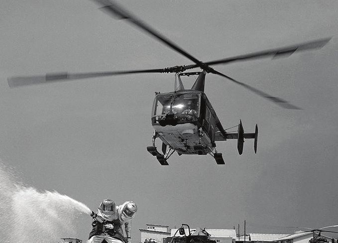
collective changes the pitch angle of all the main rotor blades          where it is required to be. Despite the complexity of the
collectively (i.e., all at the same time) and independently of           task, the control inputs in a hover are simple. The cyclic is
their position. Therefore, if a collective input is made, all            used to eliminate drift in the horizontal direction that is to
the blades change equally, increasing or decreasing total                control forward and back, right and left. The collective is
lift or thrust, with the result of the helicopter increasing or          used to maintain altitude. The pedals are used to control nose
decreasing in altitude or airspeed.                                      direction or heading. It is the interaction of these controls that
                                                                         makes hovering so difficult, since an adjustment in any one
The antitorque pedals are located in the same position as the            control requires an adjustment of the other two, creating a
rudder pedals in a fixed-wing aircraft, and serve a similar              cycle of constant correction.
purpose, namely to control the direction in which the nose
of the aircraft is pointed. Application of the pedal in a given          Displacing the cyclic forward causes the nose to pitch down
direction changes the pitch of the tail rotor blades, increasing         initially, with a resultant increase in airspeed and loss of
or reducing the thrust produced by the tail rotor and causing            altitude. Aft cyclic causes the nose to pitch up initially,
the nose to yaw in the direction of the applied pedal. The               slowing the helicopter and causing it to climb; however, as
pedals mechanically change the pitch of the tail rotor, altering         the helicopter reaches a state of equilibrium, the horizontal
the amount of thrust produced.                                           stabilizer levels the helicopter airframe to minimize drag,
                                                                         unlike an airplane. [Figure 1-12] Therefore, the helicopter
Helicopter rotors are designed to operate at a specific rpm.             has very little pitch deflection up or down when the helicopter
The throttle controls the power produced by the engine, which            is stable in a flight mode. The variation from absolutely
is connected to the rotor by a transmission. The purpose of              level depends on the particular helicopter and the horizontal
the throttle is to maintain enough engine power to keep the              stabilizer function. Increasing collective (power) while
rotor rpm within allowable limits in order to keep the rotor             maintaining a constant airspeed induces a climb while
producing enough lift for flight. In single-engine helicopters,          decreasing collective causes a descent. Coordinating these
the throttle control is a motorcycle-style twist grip mounted            two inputs, down collective plus aft cyclic or up collective
on the collective control while dual-engine helicopters have a           plus forward cyclic, results in airspeed changes while
power lever for each engine. [Figure 1-11] Helicopter flight             maintaining a constant altitude. The pedals serve the same
controls are discussed in greater detail throughout Chapter 4,           function in both a helicopter and a fixed-wing aircraft, to
Helicopter Flight Controls.                                              maintain balanced flight. This is done by applying a pedal
                                                                         input in whichever direction is necessary to center the ball in
                                                                         the turn and bank indicator. Flight maneuvers are discussed in
                                                     30
                                                          50
                                                               70
                                                                         greater detail throughout Chapter 9, Basic Flight Maneuvers.
             Fuel control or carburetor         15

                                                 5             100
                                                                    85

      Twist grip throttle
                                                                                                                  Horizontal stabilizer
                                                Throttle linkage

                                          Throttle cable
      Collective control

Figure 1-11. The throttle control mounted at the end of the collective
control.
                                                                         Figure 1-12. The horizontal stabilizer levels the helicopter airframe
Flight Conditions                                                        to minimize drag during flight.

There are two basic flight conditions for a helicopter—hover
and forward flight. Hovering is the most challenging part of
flying a helicopter. This is because a helicopter generates its
own gusty air while in a hover, which acts against the fuselage
and flight control surfaces. The end result is constant control
inputs and corrections by the pilot to keep the helicopter

1-6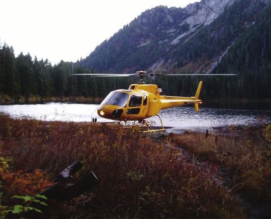
Chapter Summary
This chapter gives the reader an overview of the history
of the helicopter, its many uses, and how it has developed
throughout the years. The chapter also introduces basic terms
and explanations of the helicopter components, sections, and
the theory behind how the helicopter flies.

                                                                1-7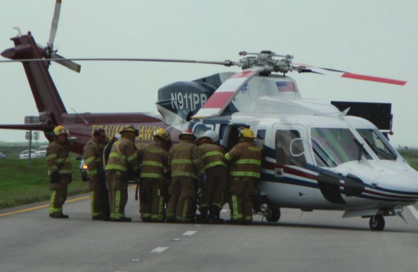
1-8
You can also read