Rain Rate Estimation with a Dual-Frequency Airborne Doppler Radar
←
→
Page content transcription
If your browser does not render page correctly, please read the page content below
Rain Rate Estimation with a Dual-Frequency Airborne Doppler Radar

      NASA Goddard/Graduate Student Summer Program (GSSP) 2010

                                      Tao Chu,
                         Department of Electrical Engineering
                            University of Massachusetts

                                Mentor: Dr. Lin Tian
                       Mesoscale Atmospheric Processes Branch
                                   GEST/GSFC

                                       Abstract:

In this study, a framework is given by which airborne dual-wavelength radar data can be
used to estimate the rain rate and other characteristic parameters of hydrometeors. The
motivation of this study is on algorithm development for the NASA IIP Unmanned Aerial
Vehicle (UAV)-based sensor HIWRAP: High Altitude Imaging Wind and Rain Profiler
(Heymsfield, et. Al., 2006), a dual-frequency (Ku and Ka), dual beam (30 and 40 degrees)
conically scanning Doppler radar that is designed for measurement of atmospheric wind
and rain. A predecessor of HIWRAP, the University of Massachusetts’ (UMass) IWRAP:
Imaging Wind and Rain Profiler (Frasier, et. Al., 2002) is an airborne Doppler Radar with
similarities in both geometry and operating principles. From the availability of IWRAP
data during Hurricane Ike of Sept 7th, 2008, it was possible to use a differential
attenuation method to develop a relationship between specific attenuation and rain fall
rate. This relationship agreed well with standard models and also model derived in the
past with the IWRAP instrument. One important implication of the derived relationship is
that it can be used for correction of attenuation due to the presence of rain in the ocean
surface backscatter.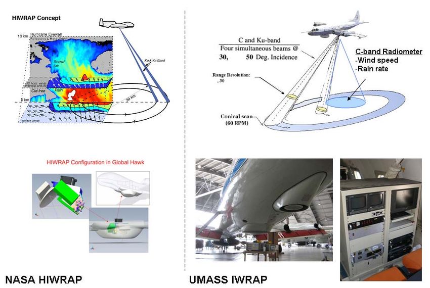
Introduction:

Hurricanes are major threats to maritime activities and coastal communities. Accurate
prediction of rain fall rate within hurricanes is crucial for predicting the intensity of the
storm. To date, air-borne and space-borne based remote sensing technique offer the best
methods to obtain precipitation measurements within a hurricane. Land based techniques,
although useful when the storm comes near shore, are limited in coverage and its ability
to provide evolutional dynamics of the storm system.

Due to limitation in space-borne instruments’ spatial resolution, airborne instruments
remain the more precise instrument due to its proximity to the observed storm. IWRAP:
Imaging Wind and Rain Airborne Profiler is an example of such an air-borne instrument.
It is designed and operated by the University of Massachusetts (UMass) for the purpose
of measuring wind and rain inside hurricanes and regularly operated abroad the NOAA
P3 aircraft platform. In order to mitigate risks of human lives and to extend the duration
of these scientific missions, NASA IIP has developed an air-borne Doppler radar
instrument known as HIWRAP: High Altitude Imaging Wind and Rain Profiler to be
deployed on the Global Hawk UAV. Technological advances in solid state transmitter
technology and aviation had made it feasible and cost effective to deploy Doppler radar
for weather research applications on such novel air-borne instrumentation platforms.

IWRAP is a dual-frequency (C- and Ku- band), dual-beam (30o and 50o), polarimetric,
and conically-scanning Doppler radar. It provides high resolution profiles of rain’s
effective reflectivity and Doppler velocity. During deployment, IWRAP is accompanied
by a radiometer, the SFMR: Step Frequency Microwave Radiometer, a C-band nadir
viewing radiometer that measures emission from the ocean and atmosphere. This
instrument senses the ocean surface wind speed and the column rain rate within the
instrument’s field of view. SFMR is used in tandem with IWRAP during missions into
hurricanes and satellite validation missions for instruments such as NASA’s QuickScat
and ESA’s ASCAT, both responsible for providing global ocean wind coverage.
IWRAP’s various level of scientific data products is available to the scientific community
through its University of Massachusetts data archive.

Similarly, HIWRAP is also a dual-frequency (Ku- and Ka- band), dual-beam (30o and
40o ) conically-scanning Doppler radar. What set it apart from IWRAP is its high altitude,
long duration capabilities flying above the storm rather than through the storm and its
technical advances highlighted in Heymsfield et. Al., 2006 [1]. Together it gives
HIWRAP the unique capability of sampling a storm with unprecedented coverage,
resolution, and sensitivity. During hurricane season in 2010, HIWRAP will participate in
the GRIP: Genesis and Rapid Intensification Processes experiment, a NASA Earth
science experiment that is being conducted to better understand how tropical storms form
and develop into major hurricanes. NASA is using the DC-8, WB-57, and the Global
Hawk UAV aircrafts configured with a suite of in-situ and remote sensing instruments
that are observing and characterizing the lifecycle of hurricanes. HIWRAP hopefully will
return with valuable data to work with. IWRAP data of previous hurricane seasons is
used for HIWRAP radar algorithm development such as the work presented in this paper.
(a)                                  (b)
Figure 1: a) HIWRAP instrument geometry and configuration on the Global Hawk UAV
b) IWRAP instrument geometry and its configuration on the NOAA P3 aircraft

Table 1: Key radar parameter comparison between the HIWRAP and IWRAP airborne
Doppler Radar instruments and their antennas
Experiment and Data Processing:

As part of the NOAA/NESDIS 2008 Hurricane Ocean Winds experiment, UMass
installed IWRAP and SFMR abroad the NOAA WP-3D aircraft. During the season, a
total of five missions were flown during various phases of hurricane Ike. Ike was the third
costliest hurricane ever to make landfall in the United States. It was the ninth named
storm, fifth hurricane, and third major hurricane of the 2008 Atlantic hurricane season. It
started as a tropical disturbance near Africa at the end of August. On Sept 1st, 2008, it
became a tropical storm west of the Cape Verde islands. By the early morning of Sept 4th,
Ike was a Category 4 hurricane, with maximum sustained winds of 145 mph. Ike passed
over the Turks and Caico islands as Category 4, with winds of 135 mph. Moving west
along Cuba, it made 2 landfalls on the island nation as a Category 4 on Sept 7th and a
Category 1 on Sept 9th. Ike made its final landfall near Galveston, Texas as a strong
Category 2 hurricane. Ike was blamed for at least 195 deaths and over $37.6 billion in
damages.

The data used for analysis was from Sept 7th, 2008, when the storm was approaching
Category 4 with sustained wind up to 150 mph in the eye wall. This mission started out
from St Croix of the US Virgin Islands. The center of the storm was approaching Cuba
southwest of the storm. The flight track was designed to go from outer edge of the storm
to the eye then repeating the straight flight path and avoid flying over land. For this
reason most of the data collected on this day were from the northeast quadrant of the
storm. One transect through the eye had attenuation characteristics that was suitable for
rain rate and attenuation analysis. This portion of the flight is highlighted in figure 2.
Data from this section of the storm is used for the remainder of our analysis work.

                 Figure 2: Flight track for hurricane Ike on Sept 7th, 2008

This IWRAP data is in netCDF scientific data format consists of reflectivity Doppler
velocity and other important navigation and ancillary data. IWRAP data variables of
interest for the purpose of data analysis are of calibrated reflectivity data in dBZ at both
C- and Ku- band. Having a conically scanning geometry, reflectivity profiles were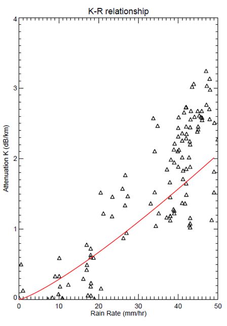
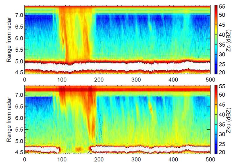
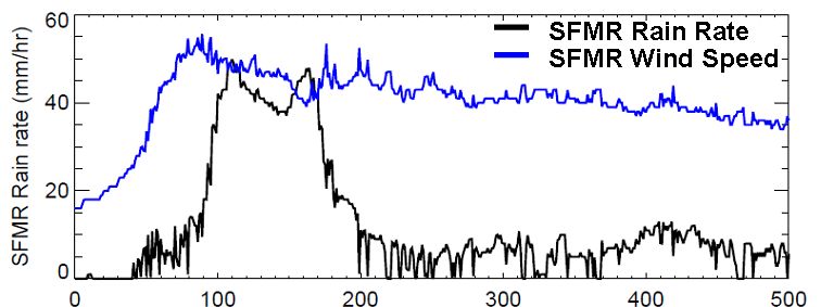
averaged into 120Hz in the azimuth direction. The rotation of the antenna is nominally 1
Hz, thus the data is in 1/3o resolution in azimuth, and 30 m in range resolution. The
airplane travels on average 125 m per second which roughly translates to one scan for
every 125 m along track distance covered.

Rain rate is the parameter of interest. Therefore we must look in the data where
significant attenuation occurs due to the rain. An eye wall of a hurricane is usually an
area where the most intense wind and rain is located. Therefore eye wall of the storm is a
good place to start looking for valid data. Utilizing data from highlighted region in figure
2, we can plot SFMR wind speed and rain rate, see figure 3. SFMR rain rate indicate an
intense rain band at the eye wall between 100 to 200 on the x-axis profile index. Sudden
increase in wind speed at the heavy rain band further supports the storm’s eye wall
characteristics. The figure displays ten minutes of actual data collection. The highest rain
rate observed is 45 mm/hr and the highest wind speed is 55 m/s.

Figure 3: SFMR wind speed (m/s) and rain rate (mm/hr) during a hurricane eye wall
penetration on Sept 7th, 2008, ten minute span

Reflectivity data measured by IWRAP has unprecedented spatial resolution. This data not
only contribute to the total rain estimation in the lower km of the atmosphere down to the
surface, but also are critical for accurately model hurricane structure and evolution of the
storm. Figure 4 shows C- and Ku- band reflectivity measurements corresponding to the
same area of measurements as shown in figure 3. IWRAP is able to capture sub-kilometer
scale structures in the rain field where SFMR could not. These fine scale features are
intense rain bands beyond the eye wall of the storm. C-band measurements see these fine
scaled rain structures. Moreover it is not significantly attenuated by the intense
precipitation in the eye wall due to its longer wavelength. The surface echoes are clearly
visible. Ku-band on the other hand at times is completely attenuated by the precipitation,
especially in the eye wall near the ocean surface at a far range distance from the radar,
where there known to have high levels of precipitation rates therefore large total path
attenuation.
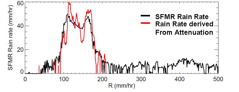
Figure 4: C-band (top) and Ku-band (bottom) Radar reflectivity in dBZ during hurricane
Ike eye wall penetration on Sept 7th, 2008, ten minute span

The estimation of rainfall rate from dual-wavelength measurements assumes that
Rayleigh scattering is the predominant mechanism at both C- and Ku- band frequencies.
This ensures that in absence of attenuation the reflectivity factors measured at both
wavelengths would be identical, assuming the radars have matched beams and the same
polarization. Figure 5 presents scatter plots of C- and Ku- band reflectivity at two
different radar ranges distance from the radar: flight level and one kilometer range
distance away from radar. The measurements at flight level show how both reflectivity
are almost identical for lowest to highest value, the difference is contained within a few
dBZ. At one kilometer range distance however, the reflectivity differs at higher
reflectivity values between the two frequencies due to the effect of attenuation. Assuming
Rayleigh, this difference in reflectivity at two different frequencies is supposed to be only
attributed to precipitation in the atmosphere.

      Figure 5: C- vs Ku-band reflectivity at altitude of: flight level and 1 km away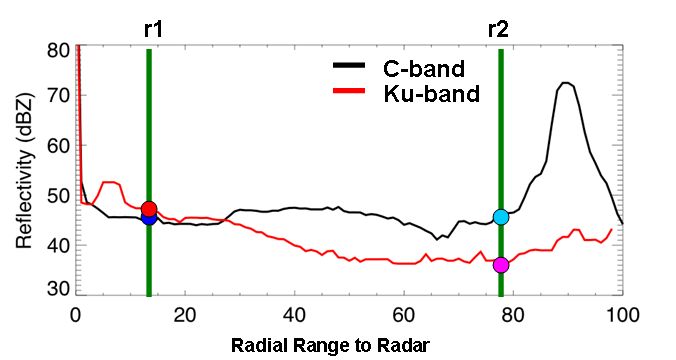
Method and Results:
Previously we established that in order to find the rain rate, we need to quantify
attenuation due by rain. Using both C- and Ku- band reflectivity data, we can derive rain
rate through what it’s called the differential attenuation technique. The idea of this
method is to acquire some dual frequency data where there are significant attenuation in
one frequency and negligible attenuation at the other. From the difference in dBZ at two
ranges, we can find the path averaged attenuation. Using the other instrument the SFMR,
with its rain rate information, we have a corresponding attenuation to each rain rate
In order to develop a relationship between K and R, we need to find a region in data of
significant attenuation between r1 and r2. An eye wall penetration usually consist of heavy
precipitation therefore a good place to look. From looking at reflectivity data shown in
figure 3. For each profile of Zc and Zku, see figure 6, if Zc(ri) and Zku(ri) denote
reflectivity factors in dBZ at ranges ri at C- and Ku-bands, the attenuation K in dB/km,
averaged over the path from range r1 to r2 is then given by:
1
K [ Z c (r2 ) Z ku (r1 ) ( Z c (r1 ) Z ku (r2 ))] (1)
2(r2 r1 )
The attenuation estimate K gives us average attenuation along the path r1 and r2
Figure 6: A single reflectivity profile of C- and Ku- band and overlaid cartoon illustration
of how differential attenuation can be calculated
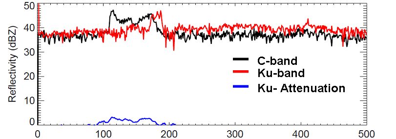
Figure 7: attenuation K for all profiles of the 10 minute data, shown with C- and Ku-
band reflectivity at 1km range distance. Notice K is positive only at eye wallAfter we calculate K for each profile, show in figure 7. We can find its relation to R of
the form in equation 2a, taking the logarithm of both sides of equation 2a, figure 8 shows
a scatter plot of specific attenuation and the SFMR rain rate estimates. A relationship
between K and R can be found using linear regression. The derived K-R relationship is
shown in table 2:
K aR b (2a)
log( K ) log(a) b * log( R ) (2b)
Figure 8: estimated attenuation K plotted with SFMR rain rate along with fitted model
Table 2: comparison of K=aRb attenuation rain modelsFrom the attenuation K, new rain rates can be derived from using the new K-R relationship developed. From figure 8, the agreement is excellent compare with the SFMR rain rate. This is expected since SFMR rain rate was utilized to derive the K-R relationship. Moreover, the K-R relationship is in excellent agreement with other models. Figure 8: SFMR rain rate compared to rain rate calculated using the K-R relationship One important application of finding a K-R relationship is the capability to correct for rain contaminated ocean surface measurement. From scatterometry principles for ocean wind purpose; higher the wind speed, the higher the ocean surface backscatter response. This relationship between the wind speed at the surface and the ocean surface backscatter is known as the model function for ocean surface wind retrieval. However under the presence of rain, ocean surface signal is weakened due to the attenuation effect of the rain. As a result, it will report lower backscatter. Since we have a K-R relationship we can correct for the attenuation knowing the rain rate reported by SFMR. As a result, the K-R relationship would help reduce the attenuation effect for ocean surface wind derivation. The result to this process is illustrated in figure 9. Figure 9: Ocean surface backscatter against wind speed for different rain rate before (top) and after (bottom) applying KR attenuation rain model
Conclusion:

We have derived a K-R relationship with the differential attenuation method using dual-
frequency radar reflectivity measurements of hurricane Ike data. The calculated model
agrees well with another standard attenuation model as well as a model derived with
IWRAP. Another technique for estimating rain is using the drop size distribution (DSD)
method was explored. This method turned out to be more involved than the time
allocated for this summer project, simulation of dual wave length DSD techniques were
carried out. The next step is to use real radar data to calculate the rain rate. This is left as
future work.

Acknowledgement:

I’m extremely grateful for the opportunity I received to participate in the summer 2010
NASA GEST/GSFC internship program. I want to first of all thank my mentor Lin Tian
who was very patient with me through out the 8 week out of 10 week period I was at
NASA Goddard. She made me feel comfortable in the environment from day one. I
appreciate her mentorship, professionalism, and camaraderie. It is the best part of my
internship experience. I want to thank Professor Stephen Frasier at the University of
Massachusetts for providing me the data and advice. My internship at Goddard would not
be possible without his guidance and support; I would of never had the opportunity to
come to Goddard if it wasn’t for him. I would also like to thank NASA for funding my
research through the Earth and Space Science fellowship. Finally I want to thank the
summer program coordinators Ms. Valery Cassasanto, Dr Tokai, Dr Jeff for making this
program possible.

References:

[1] Heymsfield, G.M., J.R. Carswell, L. Li, D. Schaubert, J. Creticos, 2006: Development of
the High-Altitude Imaging Wind and Rain Airborne Profiler (HIWRAP), Eos Trans. AGU,
87(52), Fall Meet. Suppl., Abstract IN21A-1202.

[2] Esteban-Fernandez, D., E. Kerr, A. Castells, S. Frasier, J. Carswell, P. Chang, P. Black, F.
Marks, 2005: IWRAP: the Imaging Wind and Rain Airborne Profiler for remote sensing of
the ocean and atmospheric boundary layer within tropical cyclones, IEEE Trans. Geosci.&
Rem. Sensing, 43(8), 1775-1787.

[3] Esteban-Fernandez, D., J. Carswell, S. Frasier, P. Chang, P. Black, and F. Marks, 2006:
Dual-polarized C- and Ku-band ocean backscatter response to hurricane force winds, J.
Geophys. Res., 111, C08013, doi:10.1029/2005JC003048.

[4] Richard J. Doviak and Dusan S. Zrnic: Doppler Radar and Weather Observations,
Second edition, Dover Publications, 2006, 592 pp (paperback)

[5] Battan, L.J.: Radar Observation of the Atmosphere. Chicago, IL: Univ. Chicago Press,
1973. 324 pp
                                **THANK YOU LIN**
You can also read