Long Term HSPA Evolution meets ITU IMT-Advanced requirements - White paper
←
→
Page content transcription
If your browser does not render page correctly, please read the page content below

White paper

 Long Term HSPA Evolution
meets ITU IMT-Advanced requirements

Executive summary

                                                   The volume of mobile data traffic is        The advancements to the HSPA
      Contents                                     increasing at an ever faster rate,          technology currently being finalized in
      2.	Progress in                              consistently beating predictions and        3GPP Release 11 are made by
          3GPP standards                           leading to growing demand for               implementing several key features:
      4.	Overview of the                          network improvements. One of the
          ITU IMT-Advanced ‘4G’                    major contributors to increases in          •	8 carrier aggregation, giving
          Requirements and HSPA                    traffic is the exploding popularity of         up to eight times faster data
                                                   smartphones. Another is the                    speeds compared to single
      5.	3GPP Release-11 HSPA                     increasing use of a wide variety of            carrier operation.
          features bridging the gap                applications, with frequent updates to      •	4x4 MIMO in the downlink, roughly
          to IMT-A                                 and from applications such as social           doubling peak data rates and
           5.    8-Carrier HSDPA                   networking sites and health                    system capacity for devices with
        5.       4x4 MIMO                          monitoring functions.                          four Rx antennas compared to
      		         for HSDPA                                                                        devices with two Rx antennas.
                                                   This appetite for data is driving further   •	Uplink beamforming, 2x2 MIMO and
           6.	Uplink Beamforming,                 advances in radio technology, with             64 QAM. Uplink improvements
               MIMO and 64QAM                      HSPA continuing to be deployed in              which increase the peak data rate,
           8.    HSPA+ Multiflow                   parallel with LTE to meet demand.              user performance and cell capacity.
                                                   Many performance-boosting                   •	Multiflow - increases downlink user
      9.	Long Term HSPA Evolution
                                                   innovations are being applied to the           throughputs at the cell edge.
          Performance and IMT-A
                                                   latest standard releases of both HSPA
      11. Summary                                  and LTE. Indeed, the evolution of           These features improve HSPA radio
      11. Abbreviations                            HSPA standards to meet the ITU              technology considerably, allowing Long
                                                   IMT-Advanced ‘4G’ requirements1             Term HSPA Evolution to fulfill the IMT-
                                                   shows no signs of slowing.                  Advanced requirements set by the ITU.

                                                                                               1. ITU-R Report M.2134, Requirements related to technical
                                                                                               performance for IMT-Advanced radio interface(s).

    Progress in
       3GPP standards
    Development of the Long Term HSPA               New 3GPP Release 11 features such          support. These enhancements arise
    Evolution standard beyond Release 10            as 8-carrier HSDPA and 4x4 MIMO in         from several features, including
    has been rapid. The first work to select        the downlink, as well as 64QAM             Non-contiguous 4-carrier HSDPA
    features to be included was carried out         modulation and 2x2 MIMO in the             allocation, 8-Carrier HSDPA, HSPA+
    in December 2010. Just over a year              uplink, contribute significantly to        Multiflow, Uplink Closed Loop Transmit
    later, the latest 3GPP RAN plenary              the evolution of peak data rates in the    Diversity (uplink beamforming) and
    meeting was able to close core                  HSPA radio.                                Further Enhanced Cell_FACH. The
    specification work on the first                                                            3GPP schedule for these key features
    completed items and formally set the            As important as the peak data rates        is shown in Figure 2.
    goals for the final ones. Figure 1 shows        are, Release 11 also enhances
    how the 2010 vision of Nokia Siemens            spectrum utilization, system capacity,
    Networks is becoming a reality.                 cell edge performance and smartphone

2   Long Term HSPA Evolution meets ITU IMT-Advanced requirements
Release 11

                                                                                                                   Release 10            336 Mbps

                                                                                           Release 9
                                                                                                                   168 Mbps
                                                                                                                                      40 MHz, 2x2 MIMO
                                                                      Release 8
                                                                                            84 Mbps                                   20 MHz, 4x4 MIMO
                                              Release 7
                                                                       42 Mbps                                      20 MHz
                       Release 5                                                                                   2x2 MIMO
                                              28 Mbps                                       10 MHz
                                                                                           2x2 MIMO
                       14 Mbps                                          10 MHz
     DOWNLINK

                                                                       No MIMO
                                                5 MHz                                                                                   Release 11
                                              2x2 MIMO
                        5 MHz
                                                                                                               Release 9
                       No MIMO                                                                                                            70 Mbps
                                                                                           Release 7
                                                                                                                   23 Mbps
                                                                       Release 6
                                                                                           11.52 Mbps                                     10 MHz
                                                                                                                                          64QAM
                                                                       5.76 Mbps                                    10 MHz               2x2 MIMO
                                                                                                                    16QAM
                                                          UPLINK

                                                                                            5 MHz
                                                                                            16QAM
                                                                         5 MHz
                                                                         QPSK

Figure 1. HSPA peak data rate evolution with increased bandwidth and number of antennae.

                2010                                        2011                                                                 2012

                4Q                 1Q               2Q                  3Q            4Q                1Q               2Q               3Q             4Q
  3GPP RAN
    meeting
    number #50                          #51               #52                #53            #54              #55                #56            #57            #58

                                                                       8-Carrier HSDPA

                                                Uplink closed loop transmit diversity

                                         Uplink MIMO study                                                          Uplink MIMO with 64 QAM

                                        HSDPA Multiflow study                                            HSDPA Multiflow

                                                                                                       Downlink 4x4 MIMO

                                                                   Non-contiguous 4-carrier HSDPA allocation

                                                                      Further enhanced Cell_FACH state

Figure 2. 3GPP work plan for Release 11 HSPA features.

                                                                                   Long Term HSPA Evolution meets ITU IMT-Advanced requirements                     3
Overview of the ITU IMT-Advanced
       ‘4G’ requirements and HSPA
    The IMT-Advanced requirements for
                                                      		                IMT-A minimum            HSPA prior to Rel-11            HSPA Rel-11
    ‘4G’ set by ITU can be broadly
                                                      		                requirement              (Pre-Rel-11 state of the art)   (Rel-11 improvement)
    categorized in three groups:
                                                      Peak spectral 15.0 bits/s/Hz               8.6 bits/s/Hz                   17.2 bits/s/Hz
    1.	Peak spectral efficiency                      efficiency,		                              (2x2 MIMO + 64QAM)              (4x4 MIMO)
        requirements.                                 Downlink
    2.	System performance requirements               Peak spectral 6.75 bits/s/Hz               2.3 bits/s/Hz                   6.9 bits/s/Hz
        measured in average and cell                  efficiency,		                              (16QAM)                         (2x2 MIMO + 64QAM)
        edge spectral efficiency (discussed           Uplink
        in more detail on page 9).                    Spectrum          Scalable bandwidth,      Scalable up to 20 MHz           Scalable up to 40 MHz
    3.	Other requirements, such as                   flexibility       up to 40 MHz             (4-carrier HSDPA)               (8-carrier HSDPA)
        spectrum flexibility, handover
        interruption and system latency.             Table 1: Peak spectral efficiency and bandwidth scalability requirements.

    The first and the third group of
    requirements are straightforward to
    assess, as a particular system can be             				                                       IMT-A minimum                   HSPA prior to Rel-11
    easily evaluated against the                      				                                       requirement
    requirements. The second group of
    requirements aims to provide a more               Control plane latency		                    ≤ 100 ms                        75 ms
    practical assessment of how well a                User plane latency		                       ≤ 10 ms                         8 ms
    radio system performs in diverse                  Handover         Intra-frequency           ≤ 27.5 ms                       0 ms
    deployment environments.                          interruption     Inter-frequency           ≤ 40 ms                         13 ms
    Evaluating a radio system against                 		               Inter-band                ≤ 60 ms                         13 ms
    these requirements will involve an               Table 2: Latency and handover interruption requirements.
    extensive simulation to determine
    system performance.

    Many, if not most, of the requirements
    are already within the reach of the
    HSPA radio technology, but peak
    spectral efficiency and bandwidth
    flexibility requirements listed in Table 1
    can only be met with the new features
    introduced with Release 11.

4   Long Term HSPA Evolution meets ITU IMT-Advanced requirements
3GPP release 11 HSPA features
   bridging the gap to IMT-A
3GPP Release 11 brings many
new features, with those discussed
below helping to bridge the gap
                                                          1.0
between current capabilities and
the IMT-A requirements.                                   0.9

                                                          0.8
8-Carrier HSDPA
                                                          0.7
Dual Carrier (DC) HSDPA is a 3GPP
Release 8 feature commercially                            0.6
deployed in a large number of markets.                                                         Mean packet call
                                                          0.5
However, it is limited to aggregating                                                          throughputs:
two adjacent 5 MHz radio carriers                         0.4
                                                                                               • 1 carrier: 7.9 Mbps
                                                                                               • 4 carriers: 26.8 Mbps
within the same band. In Release 9,                                                            • 8 carriers: 42.8 Mbps
the DC-HSDPA operation is extended                        0.3
to two 5 MHz carriers, each on a
                                                          0.2                                 1 carrier and 1 UE/sector
separate frequency band. Release 10
                                                                                              4 carriers and 4 UEs/sector
extends multicarrier functionality to                     0.1                                 8 carriers and 8 UEs/sector
aggregate four carriers, while Release
11 extends this still further to eight                     0
carriers. This leads to a peak data                             0    10   20    30     40    50    60     70    80     90   100

rate of 336 Mbps with 2x2 MIMO and                                        Average UE packet throughput (Mbps)
of 672 Mbps when combined with
4x4 MIMO. Release 11 also enables
aggregating non-adjacent carriers on      Figure 3: Cumulative distribution probability of the average device packet throughput
                                          for 1, 4 and 8 carriers at low offered load.
the same frequency band.

Aggregating multiple carriers brings      The gains depend significantly on the
substantial benefits for the end user     load in the system. If the load is high,
because any free resources across all     then there will be fewer free resources
                                                                                                        2-RX                      2-TX
carriers can be used flexibly. When       on the other carriers, which results in
                                                                                                        antennas                  antennas
some carriers are under-utilized,         lower gains.
because of the bursty nature of data,
they can be allocated in parallel to a    From the perspective of the ITU IMT-
user device. Unlike static allocations    Advanced requirements, the 8-Carrier
of each user to a particular carrier,     HSDPA allows for aggregating 40 MHz
every 2 ms the user device can            of spectrum, meeting the requirement                                     1-2 streams
transmit data using the carrier or        for flexible system bandwidth support
carriers that are experiencing the best   up to 40 MHz.
conditions, such as interference                                                                  Figure 4: 2x2 MIMO in downlink.
and carrier frequency, to maximize        4x4 MIMO for HSDPA
system throughput.
                                          A multi-antenna solution with 2x2
The gains can be seen in Figure 3,        MIMO has already been deployed in
                                            2-RX               2-TX                                     4-RX                      4-TX
which shows the cumulative                the  downlink in commercial  HSDPA                                                      antennas
                                            antennas           antennas                                 antennas
distribution of the average user          networks. The next step is to push
throughput and the mean packet call       the multi-antenna transmission to 4x4
delay for macro cells with an average     MIMO, which can double the peak
cell load of 1 Mbps.                      data rate and also improve the typical
                                          cell capacity and user data rates.
                                                      1-2 streams                                                   1-4 streams

                                                                                                  Figure 5: 4x4 MIMO operation in downlink.

                                                                Long Term HSPA Evolution meets ITU IMT-Advanced requirements                  5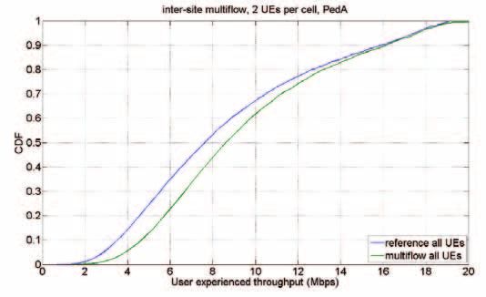
Release 5

     2100 MHz

     2100 MHz

           This can be seen in Figure 6, showing
     2100 MHz
           the average cell throughput. It can be
           seen that adding Rx antennas gives                             14
           more benefits than adding Tx
                                                                                                                                        13.05
           antennas, while the maximum gain
     2100 MHz
                                                                          12
           is achieved by using four transmit                                                                   11.66
           and four receive antennas. In that                             10
           case the system will automatically                                            9.64
           adapt the number of streams                                                                                                              4Rx
                                                                          8                                                          8.04
           from a 4-transmit antenna with                                                                                                           2Rx
           beamforming, to up to four parallel                                                               7.09
                                                                          6                                                                         1Rx
           MIMO streams.                                                            6.15
                                                                                                                                 5.59
                                                                          4                              4.69
            From the perspective of the ITU
            IMT-Advanced requirements, the 4x4                                   3.42
      Handovers
            MIMO, when coupled with 64QAM
       between                                                            2
    LTE and HSPA
            modulation, reaches 17.2 bits/s/Hz
            peak spectral efficiency, exceeding the                       0
                                                                                        1Tx                  2Tx                     4Tx
            IMT-A minimum requirement of
            15 bits/s/Hz.

           Uplink Beamforming,                              Figure 6: Average cell throughput (Mbps) with different number of Rx and Tx antennas.

           MIMO and 64QAM

           Beamforming allows uplink dual                   link budget, which translates into up to
                    4Rx     2Rx     1Rx
           antenna transmission to provide                  30% higher average uplink data rates
           better data rate coverage and lower              throughout the cell and up to 40%
                      OPEX
           interference from neighboring cells.             higher data rates at the cell edge.
           It will also double the peak uplink
           rate using dual stream transmission              In another analogy to downlink MIMO,
           and triple it when coupled with                  in very good channel conditions and
           64QAM modulation.                                when a high received signal-to-noise
           In an approach that is analogous to              ratio is possible, the user equipment
           the downlink MIMO, the mobile device             may use dual stream MIMO
           uses two transmit paths and antennas             transmission with two orthogonal beam
           to form a complex radio wave pattern             patterns. This effectively doubles the
           in the multiple base station receive             raw bit rate on the physical layer and,
           antennas. In favorable radio                     when moving from 16QAM to 64QAM
           conditions, this yields over 2 dB in the         modulation, the raw bit rate is tripled.

                 1-TX                   2 or 4 RX             2-TX                      2 or 4 RX
                 antenna                antennas              antennas                  antennas

                                                             1 stream: Beamforming
                                                             2 streams: MIMO

           Figure 7: Single Tx antenna uplink.              Figure 8: Dual Tx antenna uplink enabling
                                                            beamforming transmit diversity and MIMO.

6          Long Term HSPA Evolution meets ITU IMT-Advanced requirements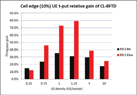
Release 5

 2100 MHz

 2100 MHz

 2100 MHz

    To achieve received signal-to-noise
    ratios that are high enough to make
 2100 MHz
    dual stream transmission with 64QAM
    possible over a significantly large area,
                                                           25.0%
    four or even eight receiver antennas,
    or a combination of both, may need                                   ISD 1km
    to be deployed. Yet again this is                      20.0%         ISD 2.8km
    analogous to what happens in
    the downlink.                                          15.0%

    Dual antenna transmission in the                       10.0%
    uplink
 Release 5  should be viewed as two
    separate features. First, there is uplink
  Handovers                                                 5.0%
   between
    beamforming, which is possible and
LTE and
 2100   HSPA
      MHz
    beneficial in most environments and                     0.0%
    which provides better uplink data rate                              0.25               1                 4                  10
    coverage. Second is the uplink dual                                        User Equipment density (User Equipment/sector)
    stream
 2100 MHz MIMO, which is possible only in
    more limited scenarios and doubles the
    uplink peak rate.                           Figure 9: Gain in average user throughput from uplink beamforming.
 2100 MHz
    Introducing 64QAM modulation does
    not require two transmit antennas, but
    when aimingCAPEX
                   for the highest peak data
 2100 MHz
    rates, it needs to be coupled with                     90.0%
    uplink MIMO. OPEX
                                                           80.0%           ISD 1km
                                                                           ISD 2.8km
    Figures 9 and 10 show the gains of                     70.0%
    beamforming on the average and cell
                                                           60.0%
    edge throughput. It can be seen that
                   Throughput gain

    gains of up to 20% and 80%                             50.0%
    respectively can be achieved.
                                                           40.0%

    From the perspective of the ITU IMT-                   30.0%
    Advanced requirements, uplink
  Handovers
                                                           20.0%
   between
    beamforming helps achieve the
LTE and HSPA                                               10.0%
    average and cell edge performance
    requirements. The uplink 2x2 MIMO                       0.0%
    together with 64QAM modulation,                                    0.25              1                  4               10
                                                                               User Equipment density (User Equipment/sector)
    achieves 6.9 bits/s/Hz peak spectral
    efficiency, exceeding the IMT-A
    minimum requirement of 6.75 bits/s/Hz.      Figure 10: Gain in cell edge user throughput from uplink beamforming.

                CAPEX

               OPEX

                                                                   Long Term HSPA Evolution meets ITU IMT-Advanced requirements      7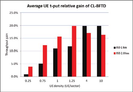
HSPA+ Multiflow
                                                          Interference                Signal                       Signal                Signal
    Another feature enabling a better use
    of resources in cellular systems is
    HSPA+ Multiflow, which is designed to
    improve cell edge data rates. Multiflow
    enables the transmission of data
    from multiple cells to a user device                                             Data stream 1           Data stream 2               Data stream 1
    at the common cell edge, instead of
    transmitting the data via a single cell
    as in HSDPA today. This is illustrated
    in Figure 11 and Figure 12 for dual cell
    Multiflow operation.
                                                     Figure 11: Conventional single-cell HSDPA.            Figure 12: HSPA+ Multiflow.
    Each of the data flows in Multiflow
    can be scheduled independently,
    simplifying the concept and enabling
    simple inter-site deployment
    without the need for tight network
    synchronization. The presence of two
                                                               10
    HSDPA flows from two cells leads to
    a doubling of the power available                              9
                                                                            no Multiflow
    for the desired signal at the device,                          8        Multiflow
    which is used to increase the overall                          7
    user throughput.                                               6
                                                                   5
    To eliminate the inter-stream
                                                                   4
    interference, the terminal should have                                 +40%
                                                                   3
    two receive antennas and interference-
    aware receiver chains. For 3GPP                                2
    Release 11, Multiflow is considered                            1
    for up to four different flows over two                        0
    different frequencies, enabling the                                            Cell edge                         Average
    radio network to send data from two
    different base stations and up to four
    different cells to a user device.
                                                     Figure 13: Cell edge and average user throughput with and without Multiflow.

    Figure 13 shows the cell edge and
    average user throughput with and
    without Multiflow. It can be seen
    that users at the cell edge particularly
    benefit from Multiflow, since they
    are the most likely to receive
    transmissions from multiple cells
    with adequate signal quality.

    From the perspective of the ITU
    IMT-Advanced requirements, HSPA+
    Multiflow helps achieve the required
    performance at the cell edge.

8   Long Term HSPA Evolution meets ITU IMT-Advanced requirements
Long term HSPA evolution
performance and IMT-A
The ITU IMT-Advanced evaluation The system performance requirements 2. ITU-R Report M.2135, Guidelines for evaluation
of radio interface technologies for IMT-Advanced.
guideline document2 details four for a candidate IMT-Advanced radio
different deployment environments and technology are shown in Table 4. The
sets performance criteria in each. evaluation criteria state that it is sufficient
Key parameters of the deployment to meet each requirement type in three
environments are described in Table 3. out of four deployment scenarios to
qualify as an IMT-Advanced radio.
Indoor hotspot Urban micro Urban macro Rural macro
InH UMi UMa RMa
BS-to-BS distance 60 m 200 m 500 m 1732 m
BS antenna elements Up to 8 Rx and 8 Tx
Total cell Tx power 21 dBm / 20 MHz 41 dBm / 10 MHz 46 dBm / 10 MHz 46 dBm / 10 MHz
BS antenna height 6 m, ceiling mounted 10 m, below rooftop 25 m, above rooftop 35 m, above rooftop
BS antenna gain 0 dBi 17 dBi 17 dBi 17 dBi
Device antenna elements Up to 2 Rx and 2 Tx
Device Tx power 21 dBm 24 dBm 24 dBm 24 dBm
Device speed 3 km/h (10 km/h) 3 km/h (30 km/h) 30 km/h (120 km/h) 120 km/h (350 km/h)
(high speed)
Carrier frequency 3.4 GHz 2.5 GHz 2.0 GHz 800 MHz
Table 3: Key deployment scenario parameters for the system performance evaluation.
Indoor hotspot Urban micro Urban macro Rural macro
InH UMi UMa RMa
Downlink average 3.0 bits/s/Hz 2.6 bits/s/Hz 2.2 bits/s/Hz 1.1 bits/s/Hz
spectral efficiency
Downlink cell edge 0.1 bits/s/Hz 0.075 bits/s/Hz 0.06 bits/s/Hz 0.04 bits/s/Hz
spectral efficiency
Uplink average 2.25 bits/s/Hz 1.8 bits/s/Hz 1.4 bits/s/Hz 0.7 bits/s/Hz
spectral efficiency
Uplink cell edge 0.07 bits/s/Hz 0.05 bits/s/Hz 0.03 bits/s/Hz 0.015 bits/s/Hz
spectral efficiency
High speed 1.0 bits/s/Hz 0.75 bits/s/Hz 0.55 bits/s/Hz 0.25 bits/s/Hz
spectral efficiency
VoIP capacity 50 users / MHz 40 users / MHz 40 users / MHz 30 users / MHz
Table 4: IMT-Advanced system performance requirements.
Long Term HSPA Evolution meets ITU IMT-Advanced requirements 9The evaluation of Long Term HSPA As shown, Long Term HSPA Evolution
Evolution performance against these meets all the IMT-Advanced
requirements was both a major performance requirements. The results
simulator development effort and a were obtained without using certain
long-lasting simulation campaign. The cell-edge performance enhancing
following figures show the simulation features such as scenario-optimized
results against the ITU IMT-Advanced scheduler or HSPA+ Multiflow, but
set requirements. assume a fairly advanced interference
suppressing receiver in the device.
4.5 0.18
4.0 DL Performance 0.16 DL Performance
UL Performance UL Performance
3.5 DL Requirement 0.14 DL Requirement
UL Requirement UL Requirement
3.0 0.12
2.5 0.10
2.0 0.08
1.5 0.06
1.0 0.04
0.5 0.02
0 0
InH UMi UMa RMa InH UMi UMa RMa
Figure 14: LTHE cell average spectral efficiency vs. IMT-A requirement Figure 15: LTHE cell edge user spectral efficiency vs. IMT-A requirement
in bits/s/Hz. in bits/s/Hz.
6 3.0%
4 Achieved voice outage
2.5% Maximum outage
2 requirement
0 2.0%
Safety Achieved C/I
margin
-2 Maximum C/I
1.5%
requirement
-4
-6 1.0%
Safety
-8 margin
0.5%
-10
-12 0.0%
InH @ UMi @ UMa @ RMa @ InH @ UMi @ UMa @ RMa @
10 km/h, 30 km/h, 120 km/h, 350 km/h, 250 users 200 users 200 users 150 users
1.0 bps/Hz 0.75 bps/Hz 0.55 bps/Hz 0.25 bps/Hz
Figure 16: LTHE high speed mobility traffic channel performance vs. Figure 17: LTHE voice outage performance vs. IMT-A requirement.
IMT-A requirement.
10 Long Term HSPA Evolution meets ITU IMT-Advanced requirementsSummary
To meet the increased network capacity • 8 carrier aggregation, giving up to In addition, a number of other
demand caused by growing mobile data eight times better user features, such as further
traffic, HSPA continues to be improved in performance. enhancements to Cell_FACH,
parallel with LTE. HSPA is currently the • 4x4 MIMO in the downlink, improve other aspects of
radio access technology serving the most increasing peak data rates and the system.
wireless broadband users worldwide and improving system performance.
the load on the system is expected to • Uplink beamforming, 2x2 MIMO These features deliver considerable
increase greatly in the coming years. and 64 QAM. Uplink improvements improvements to HSPA radio
increase the peak data rate, user technology, and as shown in this
HSPA Release 11 raises the performance performance and cell capacity. paper, Long Term HSPA Evolution
of HSPA systems significantly by offering • Multiflow - increases downlink user can fulfill IMT-Advanced
the following features: throughputs at the cell edge. requirements set by the ITU.
Abbreviations
3GPP Third Generation Partnership Project
CL-BFTD Closed Loop Beamforming Transmit Diversity
HSPA High Speed Packet Access
HSDPA High Speed Downlink Packet Access
IMT International Mobile Telecommunications
IMT-A IMT Advanced
IP Internet Protocol
ISD Inter-Site Distance
ITU International Telecommunication Union
ITU-R ITU Radio Communication Sector
LTE Long Term Evolution
LTHE Long Term HSPA Evolution
MIMO Multiple Input Multiple Output
QAM Quadrature Amplitude Modulation
UE User Equipment
VoIP Voice Over IP
Long Term HSPA Evolution meets ITU IMT-Advanced requirements 11Nokia Siemens Networks Corporation P.O. Box.1 FI-020022 NOKIA SIEMENS NETWORKS Finland Visiting address Karaportti 3, ESPOO, Finland Switchboard +358 71 400 4000 Product code: C401-00755-WP-201203-1-EN Copyright © 2012 Nokia Siemens Networks. All rights reserved. A license is hereby granted to download and print a copy of this document for personal use only. No other license to any other intellectual property rights is granted herein. Unless expressly permitted herein, reproduction, transfer, distribution or storage of part or all of the contents in any form without the prior written permission of Nokia Siemens Networks is prohibited. The content of this document is provided “AS IS”, without warranties of any kind with regards its accuracy or reliability, and specifically excluding all implied warranties, for example of merchantability, fitness for purpose, title and non-infringement. In no event shall Nokia Siemens Networks be liable for any special, indirect or consequential damages, or any damages whatsoever resulting form loss of use, data or profits, arising out of or in connection with the use of the document. Nokia Siemens Networks reserves the right to revise the document or withdraw it at any time without prior notice. Nokia is a registered trademark of Nokia Corporation, Siemens is a registered trademark of Siemens AG. The wave logo is a trademark of Nokia Siemens Networks Oy. Other company and product names mentioned in this document may be trademarks of their respective owners, and they are mentioned for identification purposes only. www.nokiasiemensnetworks.com
You can also read


