Translator VGA to HDMI - Installation and Operation Manual VGA to HDMI Converter/Scaler - Rose Electronics
←
→
Page content transcription
If your browser does not render page correctly, please read the page content below
Translator VGA to HDMI
VGA to HDMI Converter/Scaler

                            Installation
                                and
                          Operation Manual

10707 Stancliff Road                         Phone: (281) 933-7673
Houston, Texas 77099                         techsupport@rose.com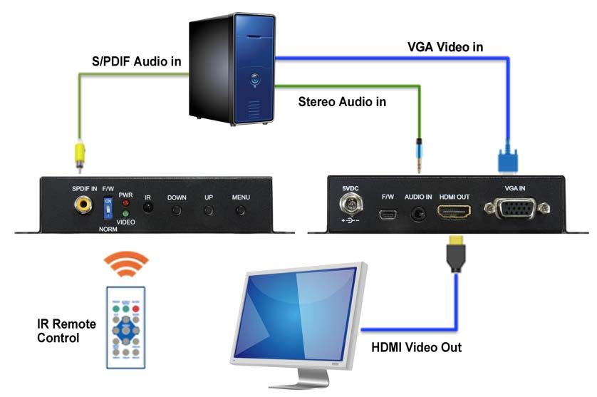
LIMITED WARRANTY

Rose Electronics® warrants the VGA to HDMI Translator to be in good working order for one year from the date
of purchase from Rose Electronics or an authorized dealer. Should this product fail to be in good working order
at any time during this one-year warranty period, Rose Electronics will, at its option, repair or replace the Unit
as set forth below. Repair parts and replacement units will be either reconditioned or new. All replaced parts
become the property of Rose Electronics. This limited warranty does not include service to repair damage to
the Unit resulting from accident, disaster, abuse, or unauthorized modification of the Unit, including static
discharge and power surges.

Limited Warranty service may be obtained by delivering this unit during the one-year warranty period to Rose
Electronics or an authorized repair center providing a proof of purchase date. If this Unit is delivered by mail,
you agree to insure the Unit or assume the risk of loss or damage in transit, to prepay shipping charges to the
warranty service location, and to use the original shipping container or its equivalent. You must call for a return
authorization number first. Under no circumstances will a unit be accepted without a return authorization
number. Contact an authorized repair center or Rose Electronics for further information.

ALL EXPRESS AND IMPLIED WARRANTIES FOR THIS PRODUCT INCLUDING THE WARRANTIES OF
MERCHANTABILITY AND FITNESS FOR A PARTICULAR PURPOSE, ARE LIMITED IN DURATION TO A
PERIOD OF ONE YEAR FROM THE DATE OF PURCHASE, AND NO WARRANTIES, WHETHER EXPRESS
OR IMPLIED, WILL APPLY AFTER THIS PERIOD. SOME STATES DO NOT ALLOW LIMITATIONS ON HOW
LONG AN IMPLIED WARRANTY LASTS, SO THE ABOVE LIMITATION MAY NOT APPLY TO YOU.

IF THIS PRODUCT IS NOT IN GOOD WORKING ORDER AS WARRANTIED ABOVE, YOUR SOLE
REMEDY SHALL BE REPLACEMENT OR REPAIR AS PROVIDED ABOVE. IN NO EVENT WILL ROSE
ELECTRONICS BE LIABLE TO YOU FOR ANY DAMAGES INCLUDING ANY LOST PROFITS, LOST
SAVINGS OR OTHER INCIDENTAL OR CONSEQUENTIAL DAMAGES ARISING OUT OF THE USE OF OR
THE INABILITY TO USE SUCH PRODUCT, EVEN IF ROSE ELECTRONICS OR AN AUTHORIZED DEALER
HAS BEEN ADVISED OF THE POSSIBILITY OF SUCH DAMAGES, OR FOR ANY CLAIM BY ANY OTHER
PARTY.

SOME STATES DO NOT ALLOW THE EXCLUSION OR LIMITATION OF INCIDENTAL OR
CONSEQUENTIAL DAMAGES FOR CONSUMER PRODUCTS, SO THE ABOVE MAY NOT APPLY TO YOU.
THIS WARRANTY GIVES YOU SPECIFIC LEGAL RIGHTS AND YOU MAY ALSO HAVE OTHER RIGHTS
WHICH MAY VARY FROM STATE TO STATE.

Copyright Rose Electronics 2018. All rights reserved.
No part of this manual may be reproduced, stored in a retrieval system, or transcribed in any form or any means, electronic or mechanical, including photocopying and
recording, without the prior written permission of Rose Electronics.
manual-translator-vga-to-hdmi-2018-04-21
DECLARATIONS OF CONFORMITY

This is to certify that, when installed and used according to the instructions in this manual, the units listed and
described here are shielded against the generation of radio interferences in accordance with the application of
Council Directives 2014/30/EU and 2014/30/EU.

This equipment has been found to comply with the limits for a Class A digital device, pursuant to Part 15 of the
FCC Rules. These limits are designed to provide reasonable protection against harmful interference when the
equipment is operated in a commercial environment. This equipment generates, uses, and can radiate radio
frequency energy and, if not installed and used in accordance with the instruction manual, may cause harmful
interference to radio communications. Operation of this equipment in a residential area is likely to cause
harmful interference in which case the user will be required to correct the interference at their own expense.

The manufacturer complies with the EU Directive 2012/19/EU on the prevention of waste electrical and
electronic equipment (WEEE). The device labels carry a respective marking.

These devices comply with Directive 2011/65/EU of the European Parliament and of the council of 8 June
2011 on the restriction of the use of certain hazardous substances in electrical and electronic equipment
(RoHS 2, RoHS II). The device labels carry a respective marking.
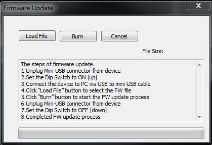
TABLE OF CONTENTS
Contents
Disclaimer                                                                    1
System Introduction                                                           1
Features                                                                      1
Package Contents                                                              2
Additional Items that may be required                                         2
Installing the VGA to HDMI Translator                                         3
  Connecting cables to the VGA to HDMI Translator                             4
  Controlling the VGA to HDMI Translator                                      4
  Push-Button Control                                                         5
  IR Remote Control                                                           6
  Remote Control using the Mini USB Port                                      7
Safety                                                                       11
Maintenance and Repair                                                       12
Technical Support                                                            12

Figures
Figure   1.   VGA to HDMI Translator cabling layout diagram                  3
Figure   2.   VGA to HDMI Translator front panel connectors and indicators   3
Figure   3.   VGA to HDMI Translator rear panel connectors and indicators    4
Figure   4.   Infrared remote control                                        6
Figure   5.   OSD on mini USB port                                           7

Tables
Table 1. OSD menu and settings                                               5
Table 2. IR controller functions                                             6
Table 3. OSD control buttons – mini USB port                                 7

Appendices
Appendix A — Specifications                                                  13
INTRODUCTION
Disclaimer
While every precaution has been taken in the preparation of this manual, the manufacturer assumes no
responsibility for errors or omissions. Neither does the manufacturer assume any liability for damages resulting
from the use of the information contained herein. The manufacturer reserves the right to change the
specifications, functions, circuitry of the product, and manual content at any time without notice.

The manufacturer cannot accept liability for damages due to misuse of the product or other circumstances
outside the manufacturer’s control. The manufacturer will not be responsible for any loss, damage, or injury
arising directly or indirectly from the use of this product (See limited warranty).

System Introduction
Thank you for choosing the Rose Electronics VGA to HDMI Translator. This product offers an easy and instant
approach for converting analog PC video (VGA) with either digital audio (S/PDIF) or analog stereo audio to
digital HDMI. VGA devices such as a PC with S/PDIF or analog stereo audio can easily connect to your HDMI
TV, simplifying presentations, demonstrations, and digital signage applications. The product will also interface
an analog KVM switch or VGA extender to a remote HDMI monitor.
The instructions in this manual assume a general knowledge of computer installation procedures, familiarity
with cabling requirements, and some familiarity with video scaling and conversion.

Features
■   Output modes are RGB, YCbCr444, YCbCr442, selectable as 480p, 720p, 1080i and 1080p
■   Maximum pixel rate is 165MHz
■   Stereo audio and S/PDIF input supported
■   De-interlacer supported
■   Active video area adjustment supported
■   Firmware upgradeable via mini USB port
■   IR remote control
■   OSD control interface
■   Supports noise reduction and video enhancement features
■   Over / under scanning adjustable
■   Video H/V mirror supported
■   Active video area adjustment supported
■   USB firmware upgradable for expanding compatibility
■   Wall-mount housing design for easy installation

                                    Translator VGA to HDMI Manual                                              1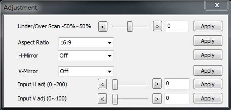
Package Contents
The package contents consist of the following items:
■   VGA to HDMI Translator
■   IR control unit
■   External power supply
■   Power cable
■   User manual
■   Installation software

Additional Items that may be required
■   HDMI cable         CAB-HDMIMM006         6ft (2.0 meter)
                       CAB-HDMIMM010         10ft (3.0 meter)
■   VGA cable          CAB-CXVMF005          6ft (2.0 meter)
                       CAB-CXVMF010          10ft (3.0 meter)
■   Audio cable        CAB-SPMM006           6ft (2.0 meter)
                       CAB-SPMM010           10ft (3.0 meter)

These items may be ordered separately from Rose Electronics

All references to HDMI and VGA cables in this document refer to the maximum recommended distances for each
cable type. Maximum recommended cable distances should not be exceeded.

                                     Translator VGA to HDMI Manual                                           2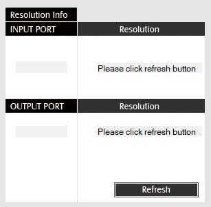
INSTALLATION and OPERATION
Installing the VGA to HDMI Translator
Unpack the VGA to HDMI Translator and check the contents of the package.
Before installing the Translator in its final mounting position, it is recommended to set up the product on a
desktop, connect the PC and monitor and any audio peripherals required, and test the product operation.
Once this operation has been confirmed, the Translator can then be fully installed into the operational
mounting. Connect the HDMI/VGA/Audio cables to the Translator and power on the product.
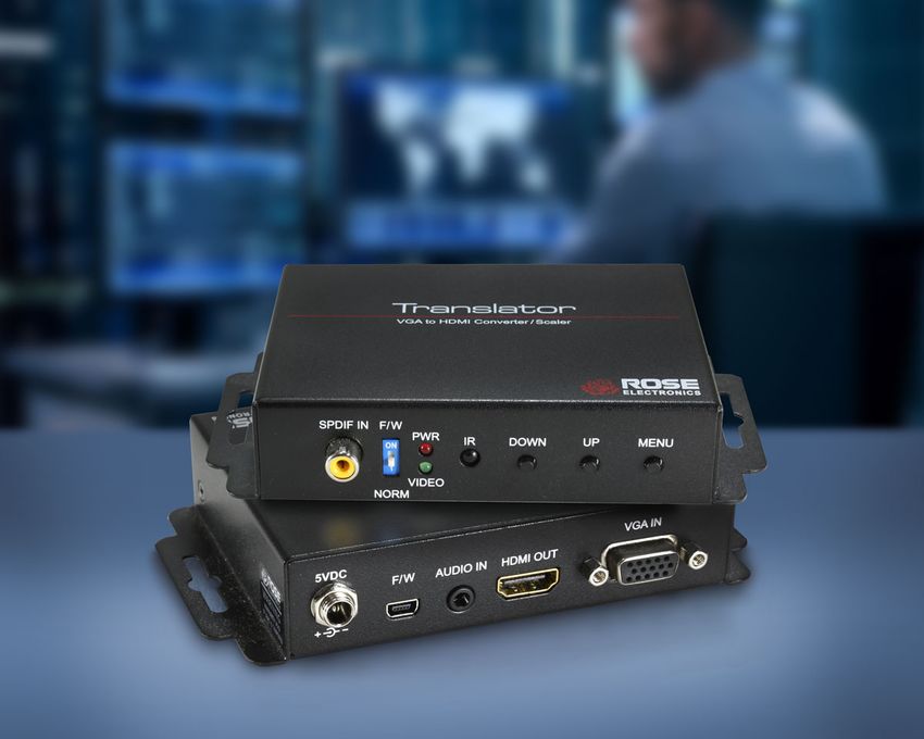
VGA to HDMI Translator – cabling schematic
Figure 1. VGA to HDMI Translator cabling layout diagram
VGA to HDMI Translator – front panel/connector layout
1 2 3 4 5
Item Type Description
1 S/PDIF Audio In Connect to the digital S/PDIF audio source
2 DIP Switch Firmware update mode. Normal operation mode
3 LED Indicator [Green] Signal indicator LED. [Red] Power indicator LED
4 IR Sensor Sensor for receiving IR commands from the IR remote
5 Push Button [Left] Down, [Mid] Up, [Right] Menu/enter button
Figure 2. VGA to HDMI Translator front panel connectors and indicators
Translator VGA to HDMI Manual 3VGA to HDMI Translator – rear panel/connector layout
1 2 3 4 5
Item Type Description
1 +5V DC Interlocking power jack for 5V DC power supply unit
2 Mini USB Firmware update and control port
3 Stereo audio in Connect to analog stereo audio source
4 HDMI out Connect to an HDMI display with an HDMI male-male cable
5 VGA in Connect to a VGA video source
Figure 3. VGA to HDMI Translator rear panel connectors and indicators
Connecting cables to the VGA to HDMI Translator
• Ensure that power is disconnected from the VGA to HDMI Translator.
• Connect the VGA cable from the video source and the HDMI display cable. Connect the analog audio
and S/PDIF cables if required. (Make sure the cables are within the recommended cable distance)
• Connect the external 5V power supply and power on the VGA to HDMI Translator.
Controlling the VGA to HDMI Translator
There are 3 methods available to control the Translator.
a) OSD controlled by push-button
b) IR Control
c) Control via the mini USB port
Translator VGA to HDMI Manual 4Push-Button Control
Select the OSD menu to display on the HDMI monitor by pushing the menu button on the front panel. Use the
up/down buttons to scroll through the menus. Use the menu button to select “enter”
OSD Menu and Settings
Output resolution
Output mode RGB, YCbCr444, YCbCr422
Output Setup Disable, white, cross, hatch, color, grey,
Default pattern windows, H-Ramp, W-HRamp, W-VRamp,
diagonal
Audio source Stereo, S/PDIF
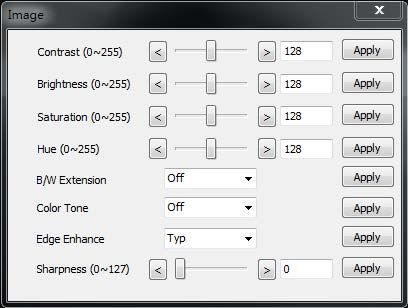
Contrast 0~255 of contrast level
Brightness 0~255 of brightness level
Saturation 0~255 of saturation level
Hue 0~255 of hue level
Image
Black/White extension Off, On
Color tone Off, skin, green
Edge enhance Typical, Mid, Maximum, Off
Sharpness 0~127 of sharpness level
Under/Over scan -50% - 50% of scan level
Aspect ratio 16:9, 4:3
Horizontal mirror Off, On
Adjustment
Vertical mirror Off, On
Horizontal shift -100~100 of horizontal shift level
Vertical shift -50~50 of vertical shift level
Input resolution information
System Firmware version
Factory reset
Table 1. OSD menu and settings
Translator VGA to HDMI Manual 5IR Remote Control
The VGA to HDMI Translator operation can be controlled using the included IR controller keypad
Figure 4. Infrared remote control
Button Function
Freeze Freeze video
Aspect Ratio Aspect ratio change
Blank Blank video
Exit Exit OSD
Enter Enter key
Up Up key
Left Left key
Right Right key
Down Down key
Menu Menu on
Input Information Source resolution information
1080p@60 Select 1080p@60 output resolution
1080i@60 Select 1080i@60 output resolution
720p@60 Select 720p@60 output resolution
480p@60 Select 480p@60 output resolution
Table 2. IR controller functions
Translator VGA to HDMI Manual 6Remote Control using the Mini USB Port
To use the remote control via the mini USB port function, first install the included software on a Windows PC
using a mini USB connection cable (not included).
Once installed, follow the screens below to set-up and control the Translator.
1 2
3 4 5 6
7
9
8
Figure 5. OSD on mini USB port
Mini USB Port - OSD Control Buttons
1 COM Port Selection
2 COM Port Detection Button
3 Output Setup Button
4 Image Button
5 Adjustment Button
6 System Button
7 Input / Output Resolution Info
8 Refresh Input / Output Resolution Info Button
9 Output Quick Selection Button
Table 3. OSD control buttons – mini USB port
Translator VGA to HDMI Manual 71. Com Port Selection
Select the available Comm Port
2. Comm Port Detection Button
Click this button to detect the Comm Port
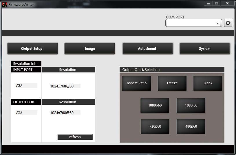
3. Output Setup Button
4. Image Button
Translator VGA to HDMI Manual 85. Adjustment Button
6. System Button
In-Sync Info: To view the current input resolution
Factory Reset Button
Firmware Update Button: Follow the steps outlined in the display below
Translator VGA to HDMI Manual 9Follow these steps for the firmware update process:
1. Unplug Mini-USB connector from device
2. Set the Dip Switch to ON []
3. Connect the device to PC via USB to mini-USB cable
4. Click the FW Update button on software
5. Click “Load File” button to select the FW file
6. Click “Burn” button to start the FW update process
7. Unplug Mini-USB connector from device
8. Set the Dip Switch to OFF []
9. Completed FW update process
7. I/O Port and Resolution Info
To display the information about the I/O Port and the applied Resolution
8. Button
To refresh the status of the converter
9. Output Quick Selection Button
Common functions for quick setting
Translator VGA to HDMI Manual 10Safety
The VGA to HDMI Translator, like all electronic equipment, should be used with care. To protect yourself from
possible injury and to minimize the risk of damage to the Unit, read and follow these safety instructions.
Follow all instructions and warnings marked on this Unit.
Except where explained in this manual, do not attempt to service this Unit yourself.
Do not use this Unit near water.
Assure that the placement of this Unit is on a stable surface.
Provide proper ventilation and air circulation.
Keep connection cables clear of obstructions that might cause damage to them.
Use only power cords, power adapter and connection cables designed for this Unit.
Keep objects that might damage this Unit and liquids that may spill, clear from this Unit. Liquids and
foreign objects might come in contact with voltage points that could create a risk of fire or electrical
shock.
Do not use liquid or aerosol cleaners to clean this Unit. Always unplug this Unit from the power source
before cleaning.
Remove power from the unit and refer servicing to a qualified service center if any of the
following conditions occur:
The connection cables are damaged or frayed.
The Unit has been exposed to any liquids.
The Unit does not operate normally when all operating instructions have been followed.
The Unit has been dropped or the case has been damaged.
The Unit exhibits a distinct change in performance, indicating a need for service.
Translator VGA to HDMI Manual 11SERVICE AND MAINTENANCE
Maintenance and Repair
This Unit does not contain any internal user-serviceable parts. In the event a Unit needs repair or maintenance,
you must first obtain a Return Authorization (RA) number from Rose Electronics or an authorized repair center.
This Return Authorization number must appear on the outside of the shipping container.
See Limited Warranty for more information.
When returning a Unit, it should be double-packed in the original container or equivalent, insured and shipped
to:
Rose Electronics
Attn: RA __________
10707 Stancliff Road
Houston, Texas 77099 USA
Technical Support
If you are experiencing problems, or need assistance installing your product, consult the appropriate section of
this manual. If, however, you require additional information or assistance, please contact the Rose Electronics
Technical Support Department at:
Phone: (281) 933-7673
E-mail: TechSupport@rose.com
Web: www.rose.com
Technical Support hours are from: 8:00 am to 6:00 pm CST (USA), Monday through Friday.
Please report any malfunctions in the operation of this Unit or any discrepancies in this manual to the Rose
Electronics Technical Support Department.
Translator VGA to HDMI Manual 12APPENDICES
Appendix A — Specifications
Part Numbers Description
CNV-VGAHDMISC Translator, VGA to HDMI Converter/Scaler
CAB-HDMIMM006 HDMI M/M 6ft (2.0m) cable
CAB-HDMIMM010 HDMI M/M 10ft (3.0m) cable
CAB-CXVMF006 USB-AB 6ft (2.0m) cable
CAB-CXVMF010 USB-AB 10ft (3.0m) cable
CAB-SPMM006 Audio 3.5mm 6ft (2.0m) cable
CAB-SPMM010 Audio 3.5mm 10ft (3.0m) cable
Chassis Dimensions (W x D x H) and Weight
Dimensions 3.6 × 3.3 × 1.1-inch, (92 × 83 × 28 mm)
Weight 0.9 lbs (0.25Kg)
Power Requirements
Power Source 100-240VAC, AC input, 5V/2A, Max 5 Watts
Video
480i 576p 720p 640×480 800×600 1024×768 1280×720 1280×800 1280×1024
Video resolutions supported
1600×1200 1680×1050 1920×1080
Video bandwidth 165MHz
Input TMDS signal 1.2 volts, peak-to-peak
Input DDC signal 1.5 volts, peak-to-peak, TTL
Audio
Stereo PCM (48KHz only)
Controls
OSD Push-button selection
IR Control IR control pad
PC OSD display via mini USB port
DIP switch Normal operation or firmware update
Connectors
1 × VGA HD15 (female)
Input 1 × 3.5mm stereo audio jack
1 × S/PDIF audio
Output 1 × HDMI (female)
LED’s
Signal Green
Power Red
Environmental
Operating Temp 32°F to 104°F (0°C to 40°C)
Storage Temp -4°F to 140°F (-20°C to 60°C)
Operating Humidity 20-90% relative, non-condensing
Approvals FCC and CE certified, RoHS compliant, WEEE
Translator VGA to HDMI Manual 13WWW.ROSE.COM ▪ sales@rose.com ▪ (800) 333-9343
Rose Electronics ▪ 10707 Stancliff Road ▪ Houston, Texas 77099
Rose USA (281) 933-7673 ▪ Rose Europe +49 (0) 2454 969442
Rose Asia +65 6324 2322 ▪ Rose Australia +61 (0) 421 247083
WWW.ROSE.COMYou can also read