PSx3xx with STO Sub Safety Function - halstrup walcher
←
→
Page content transcription
If your browser does not render page correctly, please read the page content below
Safety Manual
PSx3xx with STO Sub Safety Function
04/2021 PI

halstrup-walcher GmbH
Stegener Straße 10
D-79199 Kirchzarten
Germany

Tel. + 49 76 61/39 63-0
info@halstrup-walcher.de
www.halstrup-walcher.de

2                          7100.006654C_Safety_Manual_PSx3xx-STO
04/2021 PI

Revision Overview
 Version          Date                    Author         Content
 A                08. Feb.21              PI             Initial Revision
 B                15. Apr. 21             PI             Translation after amendments in
                                                         German version
 C                27. Apr.21              Kö             Layout and structure changes

© 2021
The Copyright on this Safety Manual remains at the manufacturer. It contains technical data,
instructions and drawings describing function and operation of the devices. Reproduction and
making available to third party is prohibited without permission of the manufacturer.

7100.006654C_Safety_Manual_PSx3xx-STO                                                      3
04/2021 PI List of Contents 4 7100.006654C_Safety_Manual_PSx3xx-STO
04/2021 PI

List of figures
Figure 1: Normal operation without test pulses ..................................................................... 16
Figure 2: Fault condition: test pulses for wiring are missing ................................................. 16
Figure 3: Normal operation with test pulses .......................................................................... 17
Figure 4: Fault condition with test pulses .............................................................................. 18

List of tables
Table 1: Applicable operating manuals ................................................................................... 6
Table 2: Description of abbreviations ...................................................................................... 7
Table 3: Definition of terms ...................................................................................................... 7
Table 4: Description and document identification of the applied standards ............................ 9
Table 5: Safety function ......................................................................................................... 19
Table 6: SIL key figures: safety function................................................................................ 19
Table 7: Key figures: diagnosis/test channel ......................................................................... 19
Table 8: Device description ................................................................................................... 20
Table 9: Performance Level (PL) ........................................................................................... 20
Table 10: Test pulses (OSSD) ............................................................................................... 20

7100.006654C_Safety_Manual_PSx3xx-STO                                                                                              5
04/2021 PI

1       General information
1.1      Purpose of this document
This document describes the safety relevant fundamentals and expected key figures when
using the positioning system PSx3xx with STO (Safe Torque Off) sub safety function.
This safety manual extends the respective operating manual:

 Bus communication          Operating manual                Document No.
 Ethernet IP                PSx3xxEIP-STO                   7100.006674
 PROFINET                   PSx3xxPNET-STO                  7100.006684
 EtherCAT                   PSx3xxECAT-STO                  7100.006704
Table 1: Applicable operating manuals

1.2      Abbreviations and definitions
Abbreviations and definitions of terms are used in the document and are explained below.

1.2.1     Abbreviations
Please find the description of the abbreviations used in the following table:

 Abbreviation          Description
 a, b, c, d, e         Identifier for Performance Level
 DC                    Diagnostic Coverage
 DCavg                 Diagnostic Coverage Average
 EMC                   Electro Magnetic Compatibility
 FIT                   Failure in time
 HFT                   Hardware Fehler Toleranz = Hardware error tolerance
 MTTFd                 Mean Time To Failure = averaged time until dangerous failure
                       occurs
 PFH                   Probability of Failure per Hour
 PELV                  Protective Extra Low Voltage
 PSE, PSS, PSW         Positioning systems of halstrup-walcher GmbH
 PL                    Performance Level see also [1] under 1.2.3 Applied standards
 SELV                  Safety Extra Low Voltage
 SIL                   Safety Integrity Level
 SFF                   Safe Failure Fraction

6                                               7100.006654C_Safety_Manual_PSx3xx-STO
04/2021 PI
Abbreviation Description
STO Safe Torque Off = a sub safety function, where a drive does not
actively generate any torque and coasts freely
OSSD Output Signal Switching Device = a fault detection measure, where
a source generates additional test pulses on a signal to be able to
detect faults in the wiring
Table 2: Description of abbreviations
1.2.2 Definition of terms
Here you will find definitions for specific, frequently used terms.
Term Definition
Coast The positioning system does generate neither torque nor
motion and is actively stopped, it coasts. The time to the
final standstill depends on the application and is
therefore not indicated. This is considered to be the safe
condition.
Positioning systems A drive family of halstrup-walcher GmbH for positioning
applications in machines
Motion task Command from the control system to the positioning
system to move a certain number of turns / steps.
Self-braking Braking moment caused by friction and entering the safe
condition.
Failure reaction time Time between occurrence of a fault and entering the safe
condition.
Reaction time Time between activation of the safety function and
entering the safe condition.
Table 3: Definition of terms
7100.006654C_Safety_Manual_PSx3xx-STO 704/2021 PI
1.2.3 Applied standards
Here you will find a description and document identification of the applied standards.
Ref. Document identification Description
DIN EN ISO 13849 Safety of machinery –
Safety-related parts of control systems
[1] DIN EN ISO 13849-1:2016-06 Part 1: General principles for design
[2] DIN EN ISO 13849-2:2013-02 Part 2: Validation
DIN EN 61800-5 Adjustable speed electrical power drive
systems.
Safety requirements.
[3] DIN EN 61800-5-1:2017-11 Duty cycle, definition see IEC 60034-1 or
VDE 0530-1
[4] DIN EN 61800-5-2:2017-11 Part 5-2. Functional safety
DIN EN IEC 61800-3 Adjustable speed electrical power drive
systems.
[5] DIN EN IEC 61800-3:2019-04 Adjustable speed electrical power drive
systems. EMC requirements and specific test
methods
DIN EN 61508 Functional safety of electrical/electronic/
programmable electronic safety-related
systems.
[6] DIN EN 61508-1:2011-02 Part 1. General requirements
[7] DIN EN 61508-2:2011-02 Part 2. Requirements for electrical/electronic/
programmable electronic safety-related
systems
[8] DIN EN 61508-3:2011-02 Part 3. Software requirements
[9] DIN EN 61508-4:2011-02 Part 4. Definitions and abbreviations
[10] DIN EN 61508-5:2011-02 Part 5. Examples of methods for the
determination of safety integrity levels
[11] DIN EN 61508-6:2011-02 Part 6. Guidelines on the application of IEC
61508-2 and IEC 61508-3
[12] DIN EN 61508-7:2011-02 Part 7. Overview of techniques and measures
DIN EN 62061:2016 Safety of machinery
[13] DIN EN 62061:2016-05 Functional safety of safety-related electrical,
electronic and programmable electronic control
systems
8 7100.006654C_Safety_Manual_PSx3xx-STO04/2021 PI
Ref. Document identification Description
[14] ZVEI Position paper CB24I Classification of Binary24V Interfaces-
Functional Safety aspects covered by dynamic
testing
Table 4: Description and document identification of the applied standards
1.2.4 Meaning of symbols and signal words
The symbols and signal words used are explained here.
DANGER
Meaning: Immediate threatening danger
Consequence of disregard: Death or serious injury
WARNING
Meaning: Potentially dangerous situation
Consequence of disregard: Death or serious injury
CAUTION
Meaning: Potentially dangerous situation
Consequence of disregard: Minor injury
NOTICE
Meaning: Notes/restrictions
Consequence of disregard: Malfunction, unexpected behaviour, potential
damage to positioning system or machine
INFORMATION
Meaning: Notes and reference to additional
documentation
Consequence of disregard: Potentially no use made of advanced
functions or misuse and misapplication of
functions
7100.006654C_Safety_Manual_PSx3xx-STO 904/2021 PI
1.3 Transportation, assembly, connections and commissioning
DANGER
Trained personnel must do assembly and electrical connection. Personnel
has to be familiar with this device and assigned by the operator of the
machine. Only trained and assigned personnel are entitled to operate the
device.
1.4 Liability claims
The positioning systems PSx3xx offer a sub safety function for STO. For implementation of
the total safety function other components and the proper observance of the here mentioned
requirements are essential. The end user of the positioning system is responsible for
assessment and valuation of the total safety function. halstrup-walcher, as supplier of a part
of the system only, refuses consequently any liability claims concerning the total system.
10 7100.006654C_Safety_Manual_PSx3xx-STO04/2021 PI
2 Description of the sub safety function
WARNING
Only single faults are relevant for the assessment regarding SIL1 and
PL c. In the bridge circuit that controls the motor current short-circuit can
occur in two semiconductors simultaneously in rare cases. This causes a
remaining risk of a sudden and short jerky movement, even in cases where
the positioning system is in the safe state.
NOTICE
The safety function STO (Safe Torque Off) corresponds to the function
emergency stop. When activating STO the positioning system does not
actively generate any torque and coasts. The value of the inherent self-
braking torque depends on the actual design. Depending on the self-
braking torque and the inertia of the application, the time varies until the
positioning system comes to a standstill.
WARNING
The STO sub safety function is realized completely in hardware. The
firmware of the positioning system does not comprise any safety function!
Functions of the firmware, e. g. status bits and measurement values, can
be used for additional information, indication and control. They must not be
used for safety functions!
INFORMATION
The positioning system does not contain any self-retaining measures for
the STO signal. Restart lockout, which might be required for certain
applications need to be implemented in the control system.
WARNING
The positioning system has a separate input for activation of the STO sub
safety function, which needs to be driven by a safety control system or
safety relay. The safety function is only ensured if the other components in
the safety chain are assessed safety-related for the requested level!
WARNING
The assessment of the safety chain must comprise the wiring also. The
positioning system offers the evaluation of test pulses (OSSD) optionally
for applications, where exclusion of faults for the wiring cannot be claimed.
In all other cases, the end user has to take care of secure wiring.
Fault exclusions regarding short-circuit between any two conductors can
be claimed according to DIN EN ISO 13849-2 [2] (see also 1.2.3 Applied
standards) for
7100.006654C_Safety_Manual_PSx3xx-STO 1104/2021 PI
permanent and protected installation, for example in cable ducts
or armoured conduits,
within an electrical installation space,
individual protection by ground connection, for example by using
individually shielded wires.
For more information, see chapter 3 Wiring and electrical connections.
2.1 Definition of the level of the STO signal
The level of the STO signal is defined as follows:
STO low 15 V STO is not triggered, drive is enabled
STO signal ≥ 5 V and ≤ 15 V undefined
In normal operation, the level of the power supply of the positioning system of +24 V
nominally is applied to the STO signal. For activation of STO the signal is set to 0V (chassis,
ground).
While STO is active, the positioning system does not accept any motion tasks. For restart of
the positioning system, please make sure that you first apply high level to the STO signal
and transfer any motion command from the control system afterwards.
2.2 STO diagnosis function
The positioning system comprises a diagnosis function for STO. If STO has been activated
and the motor is still supplied with power a fault has occurred. This fault is detected by the
diagnosis function and the positioning system is switched off using a second channel.
This condition is indicated by bit 9 of the status word on the bus. A detailed description of
the status word is available in the operating manual (see also Table 1: Applicable operating
manuals).
This failure is an indication for a potential hardware fault. The shutdown can only be
cancelled by a short disconnection from the power supply of the positioning system, for
example by loosening the plug of the power supply.
CAUTION
Do not operate the positioning system anymore and replace it by a similar
one and to return it for service and/or repair to the manufacturer!
When replacing components of the safety function please ensure that, the
replacement item has the same properties and characteristics. Otherwise,
the end user has to repeat the assessment of the complete safety function
again. After replacement of components, the commissioning test (see 2.4)
has to be repeated and documented.
12 7100.006654C_Safety_Manual_PSx3xx-STO04/2021 PI
2.3 Power supply of the STO function
WARNING
The power supply of the positioning system must comply with SELV /
PELV standard to ensure, that the maximum voltage of 60 V is not
exceeded, even in case of a fault in the power supply.
If the voltage exceeds 60 V a damage can occur which might impair the
safety function.
CAUTION
The plugs and connecting cables used for the positioning system are
frequently rated for voltages up to 30 V only. To avoid that overvoltage
impairs the sub safety or diagnosis function the voltage of the power
supply is monitored. If the power supply exceeds voltages > 31.4 V
(± 0.5 V) permanently the positioning system is disconnected from the
power supply connector internally.
NOTICE
This condition can only be cancelled by disconnecting the external power
supply, for example by turning off the power supply in the control cabinet
or by loosening the plug of the power supply.
Short peaks on the power supply, for example caused by EMC
disturbances, are filtered and do not cause turning off the positioning
system.
Please make sure that the supply voltage remains below the threshold!
7100.006654C_Safety_Manual_PSx3xx-STO 1304/2021 PI
2.4 Commissioning test after installation
After installation of a positioning system with STO sub safety function the following
commissioning test has to be conducted and documented to verify, that the STO sub safety
function is fully working. Make sure to conduct the commissioning test in the safe state of
the machine / site and avoid absolutely hazards for life and health or damage to the
positioning system or machine, e. g. by manually initiated motion of a single positioning
system.
WARNING
1. The positioning system has to be installed and the electrical
connections carried out according to the documentation of the
manufacturer and the relevant local standards.
2. Finish the software setup and test the general function by executing a
motion task. Make sure, that the motion will not cause any hazard
or damage.
3. While executing a motion task activate STO and verify that the
positioning system coasts.
4. Alternatively, if it is not possible to execute a motion task, activate
STO and then transmit a motion command. Verify that the
positioning system does not start any motion.
This commissioning test has to be conducted and documented again after exchange of any
component responsible for the safety function.
14 7100.006654C_Safety_Manual_PSx3xx-STO04/2021 PI
3 Wiring and electrical connections
The safety function is only ensured if all components in the safety chain fulfil certain
conditions. This comprises also the wiring and the electrical connections of the positioning
system.
When using standard cables fault exclusions for short-circuit between any two conductors
can be claimed when the wiring meets one of these conditions:
Permanent installation and protected against damage
STO signal uses separate jacketed cable
The cables are installed within an electrical installation space according
IEC 60204-1
Individual protection by earth connection (commonly single shielded conductors
where the shield is connected to earth)
In all cases where such fault exclusions cannot be claimed, the positioning system can be
ordered with evaluation of test pulses on the STO signal. The evaluation of the test pulses is
an additional diagnosis for wiring and connections. The source of the STO signal, most likely
a safety control system or safety relay, must support the generation of such test pulses
(OSSD) as well.
When using a hybrid connector (bus, power supply and STO signal in one connector and
therefore also in one cable) test pulses on the STO signal are most likely mandatory,
because commonly available hybrid cables do not meet the conditions above for a fault
exclusion.
7100.006654C_Safety_Manual_PSx3xx-STO 1504/2021 PI 4 Timing of STO sub safety function The following figures show the fundamental timing requirements of the STO signal. The STO input signal is presented in black, while the internal shut off signal for the motor is presented in red. 4.1 Normal operation without test pulses Figure 1: Normal operation without test pulses Figure 1 shows normal operation without test pulses for the wiring. In order to activate STO, the STO input has to be pulled low for at least 7.5 ms. This is the minimum time considering the most adverse conditions and is composed of the time for reliable detection of the STO signal state and completion of the diagnosis function. The actual shutdown of the motor occurs already directly after recognition of the STO input signal state after maximum 3.5 ms, while the remaining time is taken for the evaluation of the diagnosis function. The time for reliable detection of the STO input signal state of 3.5 ms elapses also when the STO input signal is deactivated; the positioning system is ready for new motion tasks only after this delay! 4.2 Fault condition without test pulses Figure 2: Fault condition: test pulses for wiring are missing Figure 2 shows a fault condition, again without test pulses for the wiring, where the motor current is not interrupted because of a hardware fault. The diagnosis function detects this condition and shuts down the motor using a second channel. The shutdown takes place immediately after the detection of the fault, the reaction time of ≤ 10 ms is met in all conditions. Because a hardware fault is very likely to persist, this condition can only be left by disconnecting the power supply of the positioning system! It is highly recommended to replace the positioning system with a similar one as soon as possible. 16 7100.006654C_Safety_Manual_PSx3xx-STO
04/2021 PI
4.3 Normal operation with test pulses
Figure 3: Normal operation with test pulses
Figure 3 shows normal operation with test pulses (OSSD) for dynamic testing of the wiring.
The test pulse duration ti is at least 100 µs and must not exceed 1 ms.
The interval time T between two subsequent test pulses must not exceed 1 s.
The ratio ti/T is also important. This ratio is in the range 1:100 up to 1:1000 preferably.
However, to support commonly used safety control systems, it is tolerated to exceed this
ratio by + 25 %. The classes C1 to C3 are supported according ZVEI Position Paper
[Fehler! Verweisquelle konnte nicht gefunden werden.] (see 1.2.3 Applied standards).
NOTICE
Contrary to the description in the position paper, the positioning system
evaluates the test pulses. Otherwise, the source (control system) might be
able to detect faults in the wiring as well, however in a single channel
configuration a safe shutdown is then not ensured!
For such faults in the wiring which are already detected by the source
(control system), a second shutdown path should be implemented where
necessary, e. g. by switching off the power supply of the positioning
system by the control system.
7100.006654C_Safety_Manual_PSx3xx-STO 1704/2021 PI 4.4 Fault condition with test pulses Figure 4: Fault condition with test pulses Figure 4 shows a fault condition in the sequence of the test pulses for dynamic testing of the wiring. Whenever the interval time T between two subsequent test pulses exceeds the value of 1.5 s (1.25 s ± 20 %), STO will be activated and the motor is shut down. The shutdown takes place also when the ratio ti/T exceeds the value of 1:1000 severely. An exact limit cannot be specified since the limit depends also on the absolute value of the duration ti of the test pulses. 4.5 Use of the restart lockout The positioning system comprises only self-retaining measures for the faults which are described above and which can be detected definitively. In other cases, where no explicit fault condition can be detected, the positioning system will return to normal operation as soon as STO will be deactivated! Where this is not desired, any restart lockout has to be implemented in the control system. This is also needed in cases, where test pulses for dynamic testing of the wiring (OSSD) are used and faults in the sequence of these test pulses are detected. Comparable the behaviour, when STO is activated and deactivated again, the positioning system remains in the safe state as long as an invalid test pulse sequence is detected and resumes operation as soon as the test pulse sequence is valid again. Where this is not desired, self-retaining measures have to be implemented in the control system. For this reason it is highly recommended to check the status information regularly in the control system for detection of such short-time conditions and to take appropriate measures if necessary. The test pulses are solely used for dynamic testing of the wiring. At occurrence of failures in the test pulse sequence it is very unlikely that the safety function itself is impaired and it can be expected that the safety function will be available continuously. 18 7100.006654C_Safety_Manual_PSx3xx-STO
04/2021 PI

5        Safety relevant key figures
5.1       Safety function

    Safety function: safe condition and supported safety function
    Uncontrolled stop according DIN EN 60204-1
    Stop category 0 according DIN EN 60204-1
    Safe torque off according chapter 4.2.3.2 in DIN EN 61800-5-2
    Reaction time < 10 ms1
    Failure reaction time < 5 ms1
Table 5: Safety function

5.2       Safety Integrity Level SIL
          (DIN EN 61508, DIN EN 62061, DIN EN 61800-5-2)

    Key figures: safety function
    λS       440 FIT    Failure rate – safe
    λD       244 FIT    Failure rate - dangerous
    λDD      147 FIT    Failure rate – dangerous, detected
    λDU       97 FIT    Failure rate – dangerous, undetected
Table 6: SIL key figures: safety function

    Key figures: Diagnosis/test channel
    λS       551 FIT    Failure rate – safe
    λD       576 FIT    Failure rate – dangerous
    λDD        5 FIT    Failure rate – dangerous, detected
    λDU      571 FIT    Failure rate – dangerous, undetected
Table 7: Key figures: diagnosis/test channel

    Device type             Type A                 Discrete realization of safety function

1
 Values for applications without test pulses (OSSD) on STO signal, otherwise depending on timing of test
pulses.

7100.006654C_Safety_Manual_PSx3xx-STO                                                                      19
04/2021 PI
Operation mode High Demand Demand > 1 / year
HFT 0 Hardware Failure Tolerance
SFF 85.5% Ratio of safe failures
SIL SIL 1 Achievable Safety Integrity Level
Service life 20 years Period for intended use, where the key figures
remain valid
PFH 9.7*10-8 1/h Probability of failure per hour
Table 8: Device description
5.3 Performance Level (PL)
(DIN EN ISO 13849-1)
MTTFd 100 years – high Average time until dangerous failure occurs
DCavg 60.2% – low Average Diagnostic Coverage
PL c Achievable Performance Level
Category 2 Single channel shutdown, test channel with
output (diagnosis with 2. channel shutdown),
test of safety function at every demand
Table 9: Performance Level (PL)
5.4 Test pulses (OSSD)
Parameter Min. Typ. Max.
Class Interface Typ C, class 1, 2 and 3
Test pulse duration ti 100 µs 500 µs 1000 µs
Test pulse interval T 10 ms 300 ms 1000 ms
Input resistance R 3000 Ω 3300 Ω 3600 Ω
Input capacitance CL 8nF 10nF 15nF
Inductance LL Negligible for frequencies below 1 MHz
Table 10: Test pulses (OSSD)
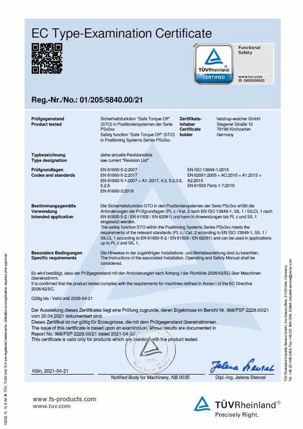
20 7100.006654C_Safety_Manual_PSx3xx-STO04/2021 PI 6 Annex 6.1 Certificate 7100.006654C_Safety_Manual_PSx3xx-STO 21
You can also read