Strong Resonance Investigation and Suppression in PMSG integrated Power Systems
←
→
Page content transcription
If your browser does not render page correctly, please read the page content below
E3S Web of Conferences 152, 03006 (2020) https://doi.org/10.1051/e3sconf/202015203006
PEEE 2019

 Strong Resonance Investigation and Suppression in PMSG
 integrated Power Systems
 Jianqiang LUO, Siqi BU*, Jiaxin WEN, Qian HU, Yong HU, and Qi WANG
 Department of Electrical Engineering, The Hong Kong Polytechnic University, Hung Hom, Hong Kong SAR, China

 Abstract. Permanent magnet synchronous generators (PMSGs) with full converters have been widely used
 in wind power generation due to its superior flexibility and controllability. However, under some
 circumstance, the oscillation modes of PMSG (POMs) may excite strong resonance with the
 electromechanical oscillation modes (EOMs) of the power system that degrades the power system small
 signal stability. In this paper, A two-open-loop subsystem model is firstly derived to analyze the oscillation
 modes. Then the POMs are investigated with modal analysis, the relationship between POMs and related
 controllers are clarified. On this basis, the strong resonance between PMSG and the external power system
 is revealed and identified. Furthermore, a five-step parameter tuning method is proposed to relocate the
 position of POM as well as suppress the strong resonance. Both modal analysis and time-domain
 simulations validate the effectiveness of the proposed method.

 1 Introduction feedback effect” between the electrical subsystem and
 the control subsystem to explain the dynamic process of
 In the last several decades, wind power generation grows instability brought by power converters.
 very fast over the world due to the requirements of As for other published works, the impact of the
 carbon reduction. To achieve better controllability, integration of FCWG on power system small signal
 various control schemes have been proposed in the wind stability with can be assessed from two aspects, i.e., the
 power generation to improve dynamic performance [1-5]. power flow changes and the dynamic interaction. [6]
 Full converter-based wind power generation (FCWG) [1, performed modal analysis to evaluate the overall impact,
 6, 7], which uses full scale converters to connect the whilst [11] and[16] investigate the impact of VSWGs on
 variable speed wind generators (VSWGs) with the power small signal stability by using damping torque analysis,
 grid, becomes very popular these years due to the wide which can be a considerable improvement in
 application and cost reduction of power electronics. understanding the overall impact.
 Among FCWG, the direct-driven permanent magnet In this paper, the strong modal resonance that threats
 synchronous generator (PMSG) is a very promising wind the power system small signal stability is studied. A five-
 generation technology, which may dominate the wind step parameter optimization method is proposed to tune
 power market in the next decade. the open-loop oscillation mode of PMSG. Since the
 However, unlike the conventional synchronous POM tuning objective function is quite complex, which
 generators (CSGs), the integration of wind power cannot be obtained analytically, the particle swarm
 generators does bring problems, such as inertia reduction, optimization (PSO) algorithm is applied to optimize
 dynamic interaction complexity, protection inaccuracy [6, controller parameters of PMSG. PSO algorithm can
 8-10]. The unexpected concern on power system stability evaluate the quality of the solution through fitness and
 also draws great attention in this field [6, 11, 12]. Since has demonstrated its advantages in solving practical
 FCWG has completely different physical structure from problems such as easy implementation, high precision
 CSGs, its impact mechanism on power system small and fast convergence [17].
 signal stability needs to be further clarified. Early works The rest of this paper is organized as follows. Section
 in this field have made some valuable progress. A model 2 introduces the modeling and linearization of PMSG
 reduction strategy proposed in [13] can reduce the model and the external power system. Section 3 presents the
 complexity and improve the computational efficiency of strong modal resonance between PMSG and the external
 a large-scale power system with increasing penetration power system. A POM tuning method is also proposed to
 of wind power generation. [14] presents a stationary αβ- optimize the controller parameters to suppress the strong
 frame impedance model to predict the stability impact of modal resonance. Section 4 gives a case study to
 PLL and its coupling effect. The mechanism of the demonstrate the proposed optimization method, while
 system instability conducted in [15] uses “positive Section 5 concludes this paper.
 *
 Corresponding author: siqi.bu@polyu.edu.hk
© The Authors, published by EDP Sciences. This is an open access article distributed under the terms of the Creative Commons Attribution License 4.0
(http://creativecommons.org/licenses/by/4.0/).
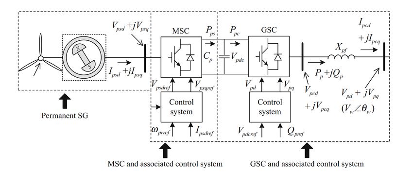
E3S Web of Conferences 152, 03006 (2020) https://doi.org/10.1051/e3sconf/202015203006 PEEE 2019 Fig. 1. Configuration of a PMSG connected the power system 2 Modeling of PMSG integrated Power System 2.1. Linearization of PMSG I g Ygg Ygw Ygn Vg Vg I = Y Yww Ywn V =Y V (4) A typical PMSG with full converters is shown in Fig. 1. wg There are four main parts: 1) The permanent magnet I N Yng Ynw Ynn VN VN synchronous generator; 2) The machine side controller where I g , Vg is the SG terminal current injection and (MSC) and the associated control system; 3) The DC- bus voltage at the connecting point; I , V is the output link, the grid side converter (GSC) and the associated current and voltage at the PCC for PMSG, which is control system; 4) The synchronous reference frame modeled as a current source; I N , VN is the current phase-locked loop (SRF-PLL) which keeps the synchronization with the power system. injection and voltage at other buses in the network; Y is The linearization equations for PMSG under x-y the admittance matrix of the multi-machine power coordinates system can be expressed as below system. d Linearize Eq(4), it can have Xpp A gp Xpp B gp V dt (1) I g Vg Ygg Ygw Ygn Vg I =Cgp Xpp I =Y V = Y wg Yww Ywn V (5) 0 VN Yng Ynw Ynn VN T T where V = Vx Vy , I = I x I y , Agp =App Bpp Rvg , Bgp =BppTg 0 , Hence, the network equation can be rewritten as 1 1 0 0 0 0 0 0 1 0 0 0 0 0 0 0 I pcq 0 =T Cgp =T (C pp -RIg) g0 g0 0 0 0 0 0 0 0 1 0 0 0 0 0 0 I pcd 0 I g YggN YgwN Vg I = Y YwwN V (6) wgN Hence, the transfer function of PMSG can be obtained, where YggN =(Ygg YgnYnn1Yng ) , YgwN =Ygw YgnYnn1Ynw , 1 I=Cgp (sI Agp ) Bgp V H (s)V (2) YwgN =(Ywg YwnYnn1Yng ) , YwwN =(Yww YwnYnn1Ynw ) . h (s) h12 (s) Hence, the linearization equations of the external where H (s)=Cgp ( sI Agp )1 Bgp = 11 . h21 (s) h22 (s) power system can be expressed as d 2.2 Linearization of External Power System ΔXg A gT ΔXg B gT I dt (7) V CgT ΔXg d I I The state space model for N generators in the rest of the power system can be written as 1 1 g YggN YgwN YwwN YwgN Dg) Cg where AgT =Ag +B( , d BgT = B( 1 1 1 g YggN YgwN YwwN YwgN Dg)YgwN YwwN , X g Ag X g Bg Vg dt (3) 1 CgT = YwwN 1 YwgN(YggN YgwN YwwN 1 YwgN Dg) Cg , I g Cg X g Dg Vg 1 dI =YwwN 1 YwwN 1 YwgN(YggN YgwNYwwN 1 YwgN Dg) 1 YgwNYwwN . The network equation is 2
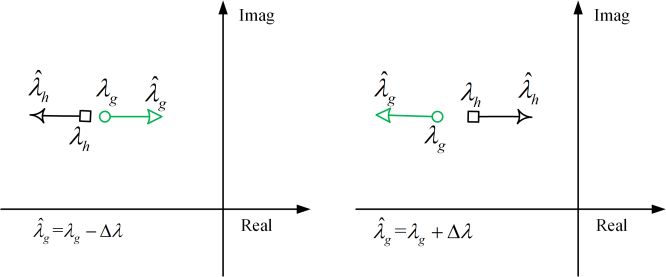
E3S Web of Conferences 152, 03006 (2020) https://doi.org/10.1051/e3sconf/202015203006 PEEE 2019 2.3 Closed-loop Model of Entire Power System For example, if h is at the right of g , the system electromechanical mode may move to the right side, the Combine Eq(1) and Eq(7), it can have PMSG mode may move to the left side, and vice versa, d as shown in Fig. 2. dt ΔXg A gT ΔXg BgT Cgp X pp From the discussion above, it can be concluded that the relative position of POM and EOM may lead to d X =B C ΔX ( A B d C )X strong modal resonance, and one of the closed-loop dt pp gp gT g gp gp I gp pp modes may deteriorate. Hence, the closed-loop interconnected model of the entire power system is obtained as 3.2 Resonance Suppression with POM Tuning To reduce the negative effect on system small signal d ΔXg AgT BgTCgp ΔXg Agp Bgp d I Cgp Xpp (8) stability, the POM tuning method is proposed to move dt Xpp Bgp CgT the POM away from EOM. There are five major steps in POM tuning: 3 Resonance Identification and (1) Identify the EOM; (2) Identify the POMs and their related state variables; Suppression (3) Compare the distance between POM and EOM, decide which of the POMs need to be tuned; 3.1 Strong Modal Resonance (4) Based on Step 2&3, tune the parameters of Based on the modeling in Section 2, the total system can controllers according to the related state variables be divided into two subsystems. The bus voltage and associated POM; variation at PCC can be regarded as the input of PMSG, (5) Use time domain simulation to verify the and the output is current injection variation that interacts effectiveness of POM tuning. with the external power system. To obtain the feasible parameters of POM, the Denote g as the critical electromechanical oscillation question can be redefined as t1 mode (EOM) of the open-loop power system. Denote h minimize f ( xi ) = Pe ( xi ) as the open loop-mode of PMSG (POM) which has the t0 (10) largest impact on the critical EOM of the power system. subject to xl xi xh l , i, h 1,..., m The distance between g and h is h g. where Pe is the active power variation on critical Based on Eq(1) and Eq(7), the transfer function of PMSG and the power system can be expressed as power tie line, xi represent the parameters of PMSG 1 g11 ( s) g12 ( s) controllers to be tuned, xl and xh are the low boundary G( s)=CgT ( sI A gT ) 1 BgT +d I = ( s g ) g 21 ( s) g 22 ( s) and high boundary of xi . f ( xi ) is the closed-loop 1 h11 (s) h12 (s) system dynamic response error function. H (s)=Cgp ( sI Agp )1 Bgp +Dgp = (s h ) h21 (s) h22 (s) The objective function f ( xi ) is proposed to minimize the critical electromechanical power oscillation in the external power system, which can be measured at critical The characteristic equation of the closed-loop bus. Once the minimal f ( xi ) is achieved, the power interconnected power system is oscillation is suppressed at the optimal level. Since the G(s) H (s) I 0 (9) objective function is not explicit, the traditional PSO Denote ̂ g and ̂ h as the solutions of Eq(9) algorithm in [17]. is implemented to solve this corresponding to g and h . According to open-loop constrained optimization problem. modal resonance theory proposed in [18], when d , i.e. h g , ̂ g and ̂ h tend to move the right side and the 4 Case Study left side of g and h . The direction of movement of ̂ g and ̂ h depends on the relative location of g and h . An example system is built as shown in Fig. 3. A PMSG is connected to the single machine infinite bus (SMIB) system. The five-step tuning is demonstrated as follows. Fig. 2. The possible movements of modal resonance Fig. 3. PMSG-SMIB system 3
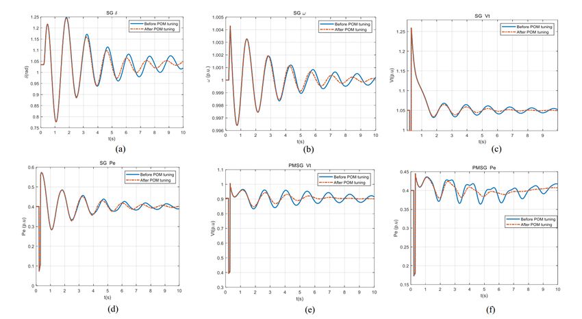
E3S Web of Conferences 152, 03006 (2020) https://doi.org/10.1051/e3sconf/202015203006
PEEE 2019

 Step 1: Identify EOM The PSO program in [17] is used to optimize the error
 Consider the SMIB system, the open loop EOM is function ∑ , where
 identified to be -0 3148 4 5190i through modal [ ], [ ]. is the angular
 analysis. speed variation from the steady-state value , which is
 used to judge the dynamic performance of the power
 Step 2: Identify POMs system. The objective of this constrained optimization
 Modal analysis is carried out on the open loop PMSG problem is to search the optimal parameters of so as to
 model with power flow profile at PCC, and thus the find the minimum of the objective function in the
 typical modes can be identified by employing time period ( , ) with the time step of 0.01s.
 participation factors with associated variables, as shown After POM tuning, the optimal parameters of the PLL
 in Table 1. controller are identified to be
 By changing the parameters of the PLL
 Table 1. The open-loop modes of PMSG controller to the optimal parameters. The PLL mode
 Frequen Damping Associated moves from -0 3145 4 5138i to -
 Mode Eigenvalue
 cy(Hz) ratio variables 0.4461+3.8346i, and thus the closed-loop EOM moves
 -2.5000±
 POM1
 22.2205i
 3.5365 0.1118 from ̂ g -0 1664 4 3213i to ̂ g -0.3769+4.4679i, the
 -2.1846± damping ratio increases twice from 3.85% to 8.41%
 POM2 3.5341 0.0979
 22.2055i indicating that the modal resonance is suppressed.
 -0.3154±
 POM3 0.2471 0.1990 Step 5: Simulation verification
 1.5528i
 -12.4730±
 POM4 11.0813 0.1763 Time domain simulations are performed to verify the
 69.6261i
 -22.4212± effectiveness A large disturbance simulation is
 POM5 15.5001 0.2244
 97.3898i performed in the PMSG-SMIB system At t 0 1s, a
 -0.0371± three-phase to earth short circuit occurs at Bus , and
 POM6 0.1293 0.0456
 0.8123i
 subsequently clears after 100ms The simulation results
 POM7 -4.9684 0.0000 1.0000
 are shown in Fig 4
 -0.3145± Fig 4(a) ~ Fig 4(d) illustrate the dynamic
 POM8 0.7184 0.0695
 4.5138i
 performance of power angle δ , angular speed ω , the
 terminal voltage Vt and active power output Pe of SG,
 Step 3: Resonance Mode Identification and Fig 4(e) ~ Fig 4(f) demonstrate the PCC voltage
 From Table 1, it is easy to find that the EOM is very and active power injection from PMSG
 close to the one of the POMs, i e POM8 (the PLL It can be seen that the modal resonance is avoided
 mode) Then POM tuning is to optimize POM8 after POM tuning. The dynamic performance of the
 power system is improved, and the small signal stability
 Step 4: Parameter optimization is enhanced.

 Fig. 4. Simulation comparison verification on POM tuning

 4
E3S Web of Conferences 152, 03006 (2020) https://doi.org/10.1051/e3sconf/202015203006
PEEE 2019

 5 Conclusion 7 J. He, L. Huang, C. Zhu, and H. Xin, "Frequency
 Support from PMSG-Based Wind Turbines with
 In this paper, the strong modal resonance between Reduced DC-Link Voltage Fluctuations," China
 PMSG and the external power system is analyzed. A Electrotechnical Society Transactions on Electrical
 POM tuning based on parameter optimization is Machines and Systems, vol. 2, no. 3, pp. 296-302,
 proposed to suppress the negative impact of modal (2018)
 resonance on power system small signal stability. Once 8 Q. Hu, L. Fu, F. Ma, and F. Ji, "Large Signal
 the objective POM is identified, the constrained Synchronizing Instability of PLL-Based VSC
 optimization problem can be determined to tune the Connected to Weak AC Grid," IEEE Transactions on
 related controller parameters. The PSO algorithm is Power Systems, pp. 1-1, (2019)
 employed to optimize the dynamic performance error 9 L. P. Kunjumuhammed, B. C. Pal, R. Gupta, and K. J.
 function and achieve a larger damping ratio of the Dyke, "Stability Analysis of a PMSG-Based Large
 closed-loop power system. The five-step case study has Offshore Wind Farm Connected to a VSC-HVDC,"
 demonstrated the effectiveness of the proposed method. IEEE Transactions on Energy Conversion, vol. 32,
 Therefore, better damping characteristics of EOM can be no. 3, pp. 1166-1176, (2017)
 achieved with the proposed POM tuning method without 10 J. Ekanayake and N. Jenkins, "Comparison of the
 auxiliary damping equipment installed, which is more Response of Doubly Fed and Fixed-Speed Induction
 economical for system operators. Generator Wind Turbines to Changes in Network
 Frequency," IEEE Transactions on Energy
 Conversion, vol. 19, no. 4, pp. 800-802, (2004)
 Acknowledgment 11 W. Du, J. Bi, J. Cao, and H. F. Wang, "A Method to
 The authors would like to acknowledge the support from Examine the Impact of Grid Connection of the
 Department of Electrical Engineering, The Hong Kong DFIGs on Power System Electromechanical
 Polytechnic University for the Start-up Fund Research Oscillation Modes," IEEE Transactions on Power
 Project (1-ZE68), Hong Kong Research Grant Council Systems, vol. 31, no. 5, pp. 3775-3784, (2016)
 for the Research Projects (25203917), (15200418) and 12 F. Wu, X. P. Zhang, and P. Ju, "Small signal stability
 (15219619), and National Natural Science Foundation of analysis and control of the wind turbine with the
 China for the Research Project (51807171). direct-drive permanent magnet generator integrated
 to the grid," Electric Power Systems Research, vol.
 79, no. 12, pp. 1661-1667, (2009)
 References 13 S. W. Xia, S. Q. Bu, X. Zhang, Y. Xu, B. Zhou, and
 J. B. Zhu, "Model reduction strategy of doubly-fed
 1 O. Carranza, E. Figueres, G. Garcerá, and R. induction generator-based wind farms for power
 Gonzalez-Medina, "Analysis of the control structure system small-signal rotor angle stability analysis,"
 of wind energy generation systems based on a Applied Energy, vol. 222, pp. 608-620, (2018)
 permanent magnet synchronous generator," Applied 14 X. Wang, L. Harnefors, and F. Blaabjerg, "Unified
 Energy, vol. 103, pp. 522-538, (2013) Impedance Model of Grid-Connected Voltage-
 2 D. Gautam, L. Goel, R. Ayyanar, V. Vittal, and T. Source Converters," IEEE Transactions on Power
 Harbour, "Control Strategy to Mitigate the Impact of Electronics, vol. 33, no. 2, pp. 1775-1787, (2018)
 Reduced Inertia Due to Doubly Fed Induction 15 S. Zhao and B. Shao, "An analytical method suitable
 Generators on Large Power Systems," IEEE for revealing the instability mechanism of power
 Transactions on Power Systems, vol. 26, no. 1, pp. electronics dominated power systems," International
 214-224, (2011) Journal of Electrical Power & Energy Systems, vol.
 3 Y. Wang, J. Meng, X. Zhang, and L. Xu, "Control of 109, pp. 269-282, (2019)
 PMSG-Based Wind Turbines for System Inertial 16 S. Q. Bu, X. Zhang, J. B. Zhu, and X. Liu,
 Response and Power Oscillation Damping," IEEE "Comparison analysis on damping mechanisms of
 Transactions on Sustainable Energy, vol. 6, no. 2, pp. power systems with induction generator based wind
 565-574, (2015) power generation," International Journal of
 4 Y. Li, Z. Xu, and K. P. Wong, "Advanced Control Electrical Power & Energy Systems, vol. 97, pp.
 Strategies of PMSG-Based Wind Turbines for 250-261, (2018)
 System Inertia Support," IEEE Transactions on 17 D. Cristian, C. Barbulescu, S. Kilyeni, and V.
 Power Systems, vol. 32, no. 4, pp. 3027-3037, (2017) Popescu, "Particle swarm optimization techniques.
 5 J. Fang, P. Lin, H. Li, Y. Yang, and Y. Tang, "An Power systems applications," in 6th International
 Improved Virtual Inertia Control for Three-Phase Conference on Human System Interactions (HSI),
 Voltage Source Converters Connected to a Weak (2013)
 Grid," IEEE Transactions on Power Electronics, pp. 18 W. Du, J. Bi, and H. Wang, "Damping Degradation
 1-1, (2018) of Power System Low-Frequency
 6 J. Quintero, V. Vittal, G. T. Heydt, and H. Zhang, Electromechanical Oscillations Caused by Open-
 "The Impact of Increased Penetration of Converter Loop Modal Resonance," IEEE Transactions on
 Control-Based Generators on Power System Modes Power Systems, vol. 33, no. 5, pp. 5072-5081,
 of Oscillation," IEEE Transactions on Power (2018)
 Systems, vol. 29, no. 5, pp. 2248-2256, (2014)

 5
You can also read