Telescopic On-Shore Tower - Esteyco
←
→
Page content transcription
If your browser does not render page correctly, please read the page content below

Telescopic On-Shore Tower

                                                                                                        Ramón López Mendizábal
                                                                                       Energy Director, ESTEYCO, Barcelona - Spain
                                                                                                         ramon.lopez@esteyco.com

1. Introduction                                                     the off-shore market but also on on-shore wind farms where
                                                                    large, costly and scarce cranes are no longer required when this
In 2011 ESTEYCO started research activities on a disruptive
                                                                    solution is implemented.
solution for the substructure of offshore wind turbines and
in 2013 a self-lifting telescopic tower came as a solution.         That’s the case of India, where higher and more powerful
Such technology was developed focusing on the capability of         turbines are expected to appear as a way of putting down
commissioning off-shore wind turbines and its substructures         the LCoE. Dealing with such heights from 140m up, requires
with full independence of the costly and scarce heavy-lift          solutions beyond conventionalism and the self-lifting precast
vessels. This technology was initially proven in 2015 with an       concrete tower by ESTEYCO is ready to face this challenge,
on-shore prototype in Daganzo (east of Madrid) and again in         as it is doing right now somewhere else with the design and
Q2 2018 in Gran Canaria Island -first off shore WTG in Southern     upcoming construction of the tallest tower in the world, with a
Europe and first in the world that does not need any significant    HH of 175m.
and expensive marine means- with the construction of the self-
                                                                    The solution, in general terms, is formed by several prismatic
installing bottom-fixed offshore wind turbine designed, built and
                                                                    concrete sections which at the same time are formed by several
certified by ESTEYCO.
                                                                    prefabricated concrete panels V-shaped, C-shaped or just flat,
Its design and construction are based on pioneering experience      depending on the case. These sections are preassembled one
when it comes to conventional precast concrete towers. Since        inside the other prior to the selferecting phase. Additionally,
ESTEYCO’s first precast concrete tower realization in 2004,         the most upper steel tubular section from conventional steel
more than 1600 towers for several turbine manufacturers have        towers can be used combined with the previous configuration
been built, with hub heights ranging from 80m to 120m.              (becoming a hybrid solution) as a variable to reduce the CoE,
                                                                    if applicable.

                                                                    The solution, patented by ESTEYCO, uses heavy-lift strand jacks
                                                                    always acting at a 40-50m height which are reused to lift one
                                                                    tower section after the other. The recoverable jacks that lift each
                                                                    section are supported by the one below, which also guides
                                                                    the hoisted section as it rises, in a self-installing procedure in
                                                                    which the tower itself is the only supported structure required,
                                                                    as stated, always working from a single access platform at 40-
                                                                    50m height.

                                                                    2. Description of the Solution
                                                                    The combination of prefabricated concrete sections with heights
                                                                    around 25m and steel tubular sections from conventional steel
                                                                    towers to shape the tower (full concrete or hybrid) depends
            Figure 1: Telescopic On-Shore Tower                     on the overall cost analysis once the turbine is defined as a
                                                                    known variable.
The increasing hub-height demands -considering already
heights from 140 to 190m- at certain wind farms, driven by          Such analysis is based on the study of the wind farm location
challenging non-conventional renewable energy policies and a        and the precast concrete panel’s factory location (within
market where reduction of the CoE is the main driver, the self-     or outside the wind farm), the lifting means to be used to
lifting telescopic tower has become a key solution not only on      manipulate the precast panels, the transport availability and

 February - March 2020       Indian Wind Power                                                                                      27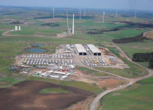
restrictions between the two locations, geometrical aspects        The steel upper part contains 3 sections totaling 65m long with
such as the blade tip and the steel sections geometry to be        a bottom diameter of 4.3m.
used, the expected production, the type of cranes available and
                                                                   Below the steel sections there are 4 concrete levels made up of
the local costs variation (labor and materials).
                                                                   precast concrete V-shaped panels prestressed with pretensioned
On this section, and as an example, a hybrid tower for a 3.X       bonded strands totaling around 100m with panels from 40 Tn
MW turbine and 165m HH composed by 3 standard steel                to 70 Tn weight aprox.
sections at the upper level and 4 concrete sections at the lower
levels is explained.

                                                                      Figure 4: Plan view of different levels cross-sections

                                                                   Every concrete panel has concrete flanges at both ends to
                                                                   enable the connection between the different sections by means
                                                                   of the horizontal joints.

                                                                   Panels of the same section are connected by means of
                                                                   concrete-filled vertical joints while the connection between
                                                                   each section is achieved by means of a grout-filled horizontal
     Figure 2: General view and main dimensions and                joints with posttensioned bolts.
                   weights of the tower

                                                                       Figure 5: General view of V-shape concrete panels

  Figure 3: General views of the tower in folded position              Figure 6: Joints between panels (vertical joint) and
           (before lifting) and unfolded position                                    sections (horizontal joint)

28                                                                     Indian Wind Power                  February - March 2020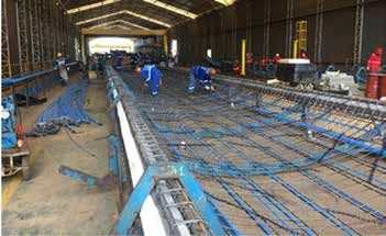
As a matter of example, the next table summarizes some likely figures for a 165mHH hybrid precast telescopic tower prototype:

                Num. panels                           Panel                                                    Panel      Section
                                 Panel weight                   Panel length     Panel width   Panel width*
                 per section                        thickness                                                 volume      weight
      T4              3               79              0.18         24.65            4.84          5.44         31.5         248
      T3              6               45              0.15         24.65            2.73          3.33         18.0         295
      T2              6               54              0.15         24.65            3.38          3.98         21.5         348
      T1              6               64              0.15         26.15            4.03          4.63         25.5         407

* Including reinforcement bars at both sides / Weight in metric ton (T) and dimensions in meters (m)
Table with main dimensions and weights of concrete panels

3. Construction Process                                               The manufacturing process consist of the following sub-
                                                                      processes:
The construction process of the precast concrete telescopic
tower involves the following stages:                                  ²    Reinforcing steel arrangement of the panel

²    Manufacturing of precast concrete panels.                        ²    Prestressing panel system

²    Transport of the panels.                                         ²    Panel concreting

²    Pre-assembly of the panels, conforming levels.                   ²    Painting of the outer surface (optional, as per client
                                                                           demand)
²    Upper steel tower, rotor and nacelles assembly.
                                                                      ²    Installation of temporary and permanent internal elements
²    Self-erection system (3 lifts)
                                                                      The following pictures show the reinforcing steel arrangement
Following, all these stages are briefly outlined.
                                                                      of the panels and the concreting phase in a conventional
3.1. Manufacturing of the precast concrete panels                     concrete tower factory.

As mentioned before, the tower is composed by levels,
which in turn are composed by precast concrete panels. The
manufacturing of these panels is carried out on a factory either
within or outside the wind farm.

                                                                               Figure 9 and 10: Reinforcement of the panels.
    Figure 7 and 8: General view of the precast panels                                   Concreting of the panels

 February - March 2020          Indian Wind Power                                                                                 29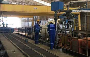
The following pictures were taken during the Off-shore Gran
Canaria Island telescopic concrete tower prototype construction
yard.
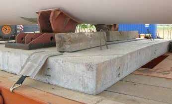
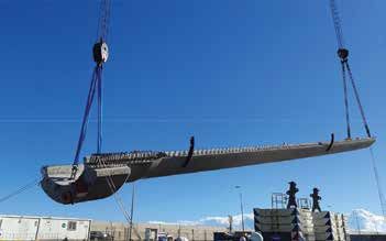
Figure 11: Panel handling
It is important to highlight the concepts of scalability and
modularity of the factory, allowing to adapt the weights and
dimensions of the panels to many different constraints and
particularities (stockage capacity, transport limitations, etc…). Figure 13 and 14: Transport of concrete panels with
Thus, the initial investment may be well adapted to the size of truck and dolly
the specific project.
3.3. Pre-assembly of the panels
3.2. Stockage and Transport As a general description, the tower pre-assembly consists of
positioning the concrete panels from inside out (starting with
After the manufacturing process, the panels are stocked inside
T4 and finishing with T1) on top of the foundation pedestal
the facilities of the factory, waiting to be transported to their
slab by using a 500 Tn mobile crane or similar and specifically
final locations. designed reusable tools. Once the panels pre-assembly is
finished, the assembly of the steel tubular sections, nacelle
and rotor takes place by using a 600 Tn crawler crane or
similar, regardless of the final height of the tower, as all these
installation works take place at a limited height (40-50m).
Figure 15: Concrete panels pre-assembly stages on top
of the pedestal slab.(T4 stability by mans of internal
tempoarary props)
The main activities included in the pre-assembly stages are as
Figure 12: General view of the factory stock area follows:
Handling of the panels within the factory is made by pairs or ² Previous works on top of the pedestal.
individual gantry cranes - depending on the available capacity-
² Concrete panels lifting from trucks and rotation to vertical
and transported to the final location thanks to conventional
position (T4).
extensible trucks. The supporting tools for the panels are made
of steel and adequately positioned for each panel dimension ² Positioning and levelling of concrete panels (T4).
in the truck. ² Execution of vertical joints (T4).
30 Indian Wind Power February - March 2020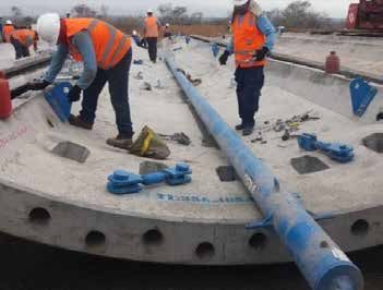
²    Panel lifting, positioning and leveling and execution of        The following step consists of tilting the panels to its vertical
     vertical joints (T3, T2, T1).                                   position to assemble the first tubular concrete section T4.
²    Filling with grout of T1 horizontal joint with the pedestal.    They will be placed on top of the installed temporary supports.
                                                                     External vertical jacks will keep the panels vertically aligned
²    Pre-assembly tools removal.                                     when concreting the vertical joints.
The previous works on site consist of setting up the central axis
and installing the temporary supports both on the pedestal top
slab.

       Figure 16: Temporary concrete panels support

The panels need some prior installation of internal elements
such a working platform, internal props on T4 to provide stability                  Figure 19: Tilting of the panels
once its panels are erected or vertical joints external jacks to
keep contiguous panels vertically aligned, among others.

                                                                              Figure 20: External jacks on vertical joints

                                                                     Once the T4 section is installed, the same procedure is applied
                                                                     on T3, T2 and T1. The stability of the panels on sections T3, T2
                                                                     and T1 is achieved by means of positioning plates attached on
                                                                     the upper flange of the panels connected to T4.

                                                                     Once all panels are pre-assembled and vertical joints are filled,
                                                                     the horizontal joint of level T1 with the pedestal can be filled
                                                                     with grout. The bolts will be placed after T1 preassembly.

      Figure 17 and 18: Internal elements installation
            (working platform and prop on T4)                        Figure 21: Vertical joints      Figure 22: T1 horizontal joint

32                                                                       Indian Wind Power                   February - March 2020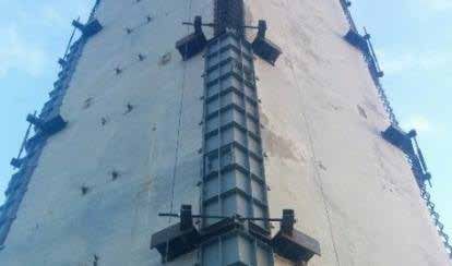
3.4. Upper steel tower, rotor and nacelle assembly                       ²    Performing T2-T1 horizontal joint.

Once the concrete panels have been pre-assembled, and prior              ²    Dismantling of auxiliary elements.
to the lifting phase, the steel segments, if existing, turbine           On the following image, all elements installed on the preparation
and blades are installed. In case the telescopic tower is a full         phase are shown. Mainly, the elements to be placed on the
concrete tower this phase will consist of installing just the            preparation phase are the platforms on Level 1 and Level 2, the
connection steel adapter, the turbine and blades.

Figure 23: Upper steel tower, rotor and nacelle assembly

3.5. Self-lifting phase                                                                 Figure 27: Tower lifting process
Once the steel tower sections and turbine have been installed,
                                                                         guidance system, the upper lifting kits with the strand jacks, a
the tower can be lifted. The key of the lifting process is the use
                                                                         system to collect the strands and setting up the power system.
of high capacity lifting jacks, and their efficiency for large heights
allowing a much lower price than a conventional crane. This              Once the preliminary stage is fulfilled, the three (3) lifting
system is based on a proven technology in multiple industries,           phases start. On the next image, the lifting phases of T3 and
with a track record of over 30 years.

Heavy lifting is made with strand jacks that are attached to the
top of the outer section of the concrete tower. All the required
works are performed from a single platform, reducing the risk
of personnel moving up and down.

                                                                                 Figure 28: Auxiliary elements arrangement

                                                                         T2 are shown together with the connection of each horizontal
                                                                         joint by means of a prestressing bars and shear keys filled with
                                                                         grout. The grout is poured in the keyed joint once the bars
                                                                         have been prestressed, adding stiffness and water-tightness to
                                                                         the joint and protecting the elements within the tower.
       Figure 24, 25 and 26: Stand- jack positioning
The main activities included in the lifting phase are as follows:
²    Preparations of all auxiliary elements and installing jacks at
     T3 upper flange.
²    Inner section T4 lift with jacks reacting on T3 outer section.
²    Performing T4-T3 horizontal joints.
²    Jack displacement from T3 upper flange to T2 upper
     flange (some centimeters outwards).
²    Lifting of T2 section.
²    Performing T3-T2 horizontal joint.
²    Jack displacement from T2 upper flange to T1 upper
     flange (some centimeters outwards).                                       Figure 29: Stages of the lifting process: lifting,
²    T2 lift with jacks reacting on T1 upper flange.                          prestressing, relocation of jacks and lifting again

 February - March 2020         Indian Wind Power                                                                                       33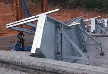
Once the lifting phase has finished, all auxiliary elements and        for steel leading to overall cost reduction up to 10% depending
lifting equipment is removed and taken to the next tower to            on the case.
start the process again.

4. Manufacturing And Assembly Rates
The rate at which regular height towers are generally produced
in the wind energy sector is 2 tower/week. These rates haven’t
ever been achieved when heights go over 120-130m. However,
ESTEYCO’s self-lifting technology is able, after the usual learning
curve that drives these kinds of processes, to get very close,
providing construction schedules that may fulfill even the most                      Figure 30: Braced foundation 3D
challenging projects.
                                                                       This solution brings not only a CAPEX reduction but also an
4.1. Manufacturing rates                                               increase of the AEP since the foundation geometry rises the
                                                                       pedestal up to 6m maximum above the ground level and hence
Considering the on-shore telescopic tower prototype, the               the hub height for a defined tower. With a hub height increase
number of panels per tower required would be 21 (3 panels              and a favorable shear gradient the AEP can be increased by
for T4 and 6 panels on T3, T2 and T1). A factory with a serial         1-3%, depending on the wind shear of the specific location.
production of 21x2 panels/week would require two parallel
working lines with one mold for each type of panel on each             Based on the assumption that the tower door is placed on the
working line.                                                          foundation itself, the general geometry of a braced foundation
                                                                       compared to a conventional foundation for a precast telescopic
4.2. Pre-assembly rates                                                tower is shown next.

The pre-assembly procedure considers a group of 3 towers
where specialized teams perform the same activity on each
tower in a “batch working” manner instead of a “one-piece
working” manner. This system provides 3 preassembled towers
every eighteen working days (3x6-day weeks). A 2 tower/week
schedule would just need to double the rate during half of the
time, without impacting in the unitary cost.
                                                                          Figure 31: Braced foundation for a telescopic tower
4.3. Steel upper segments, rotor and nacelle
assembly rates
This phase will be performed right after the pre-assembly phase
once every tower is fully preassembled. In a same “batch
working” manner, a cluster of three towers would be operated
together to avoid changing crane configuration to place all steel
elements one after another on one single tower.

4.4. Self-erecting phase                                               Figure 32: Conventional foundation for a telescopic tower
Following the same approach as the preassembly procedure,
the self-erecting phase consists of a production of three towers       6. Conclusions
every eighteen working days (3x6-day weeks) with 3 lifting sets.
                                                                       The self-lifting telescopic tower is ready to enter in wind energy
As a reference all the previous works prior to the first lift take 2
                                                                       markets as India, where a tight competition brought by the
days, each lifting phase takes 1 day, and activities related to the
                                                                       auction system is currently taking place. This technology will
horizontal joints execution amounts 2 days per horizontal joint.
                                                                       make possible to reach hub heights not even considered so
                                                                       far, as a result of the avoidance of big and expensive assembly
5. Enhancement.            Precast      Braced       Foundation
                                                                       cranes, since not only the tower but also the turbine is installed
Posibility of Use
                                                                       at a very reasonable height. The technology is available for
Driven by the reduction of the CoE, Esteyco came up with               every turbine manufacturer or developer willing to go beyond
the braced foundation patented solution where quantities of            the current limits, putting down the LCoE to the greatest extent,
materials are reduced up to 40% for concrete and up to 25%             thus maximizing the profit of the project.

34                                                                         Indian Wind Power                   February - March 2020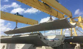
You can also read