The dynamic load test of two seismic resistance of steel structures EBF and RBS
←
→
Page content transcription
If your browser does not render page correctly, please read the page content below

IOP Conference Series: Materials Science and Engineering

PAPER • OPEN ACCESS

The dynamic load test of two seismic resistance of steel structures EBF
and RBS
To cite this article: J I Rastandi et al 2021 IOP Conf. Ser.: Mater. Sci. Eng. 1041 012005

View the article online for updates and enhancements.

 This content was downloaded from IP address 46.4.80.155 on 15/09/2021 at 13:33
2nd Conference on Innovation in Technology (CITES 2020) IOP Publishing
IOP Conf. Series: Materials Science and Engineering 1041 (2021) 012005 doi:10.1088/1757-899X/1041/1/012005

The dynamic load test of two seismic resistance of steel
structures EBF and RBS

 J I Rastandi1, M Orientilize1, C Ashilah2, D Apritasari2
 1
 Civil Engineering Department, Universitas Indonesia, Kampus UI Depok, 16424 Indonesia
 2
 Postgraduate Students of Civil Engineering Department, Universitas Indonesia

 Corresponding author: mulia@eng.ui.ac.id

 Abstract. The non-destructive dynamic loading test has been conducted on two seismic
 resistance of steel structures, reduced beam section (RBS) and eccentric braced frame (EBF).
 Eccentric mass shaker was used to excite the 1-storey 1-bay steel structure. Two dynamics
 parameters were obtained which were the natural frequency and the damping ratio. A finite
 element analysis was performed using OpenSees software to get a comparison result. Similar
 natural frequency and displacement response were obtained from the test and the FE Analysis.
 The Natural frequency of RBS and EBF was around 3.614 Hz which is similar to the FE
 analysis as 3,623 Hz. Meanwhile the damping ratio is 3.149%. The natural frequency of the
 EBF structure is around 6.0 to 6.13 Hz, while the FE analysis result is 6.13 Hz. The damping
 ratio from test results is between 2.04 – 2.06%.

1. Introduction
Seismic resistance structural system has been developed for decades and steel structure have several
varieties. The concept of the system is by designing the weaker part as a place of energy dissipation
during earthquake which is named as plastic hinge. Special Moment resisting frames (SMRF) and
Eccentrically braced frame (EBF) are two of seismic resistance system for steel structures.
 SMRF which is known as reduced beam section (RBS) was proposed to enforce the form of plastic
hinge away from the panel zone by designing RBS as the weaker section. The beam flange is cut in
circular radius on the top and the bottom of flange to reduce the area at the beam end. Hence, the
plastic deformation form there resulting the energy dissipation during earthquake. Several research
about RBS has been carried out since 1996 and during the last ten years the research still have been
done to improve its performance. [1],[2],[3],[4],[5],[6].
 The EBF combines the high elastic stiffness characteristic of a concentrically braced frame (CBF)
and the energy dissipation stability of a moment resisting frame (MRF). The system consists of a link
which is designed as a weaker section to allow the plastic deformation. The longer link allows energy
dissipation through flexural yielding while a shorter link dissipates energy through shear yielding.
Shear yielding allows for the development of plastic deformation without the formation of excessive
local strain, which is prevalent in flexural yielding [7]. Shear yielding provides a larger energy
dissipation capacity than flexural yielding [8]. For that reason, there are three parameters that must be
considered when designing an EBF system: bracing configuration, link length, and link section
properties. In long links—often referred to as flexural links—yielding occurs only in the ends of the
link where plastic hinges form. It is for this reason that EBF systems with shear links are more stable
and more ductile than flexural links. However, for architecture reason, the flexural link is preferable
since this system allows for a larger clearance than that of shear link EBFs.
 Content from this work may be used under the terms of the Creative Commons Attribution 3.0 licence. Any further distribution
 of this work must maintain attribution to the author(s) and the title of the work, journal citation and DOI.
Published under licence by IOP Publishing Ltd 1
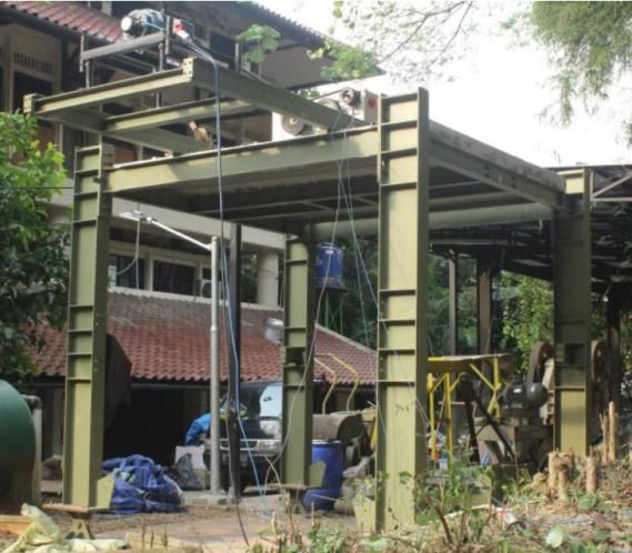
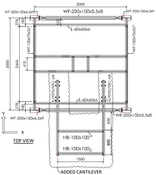
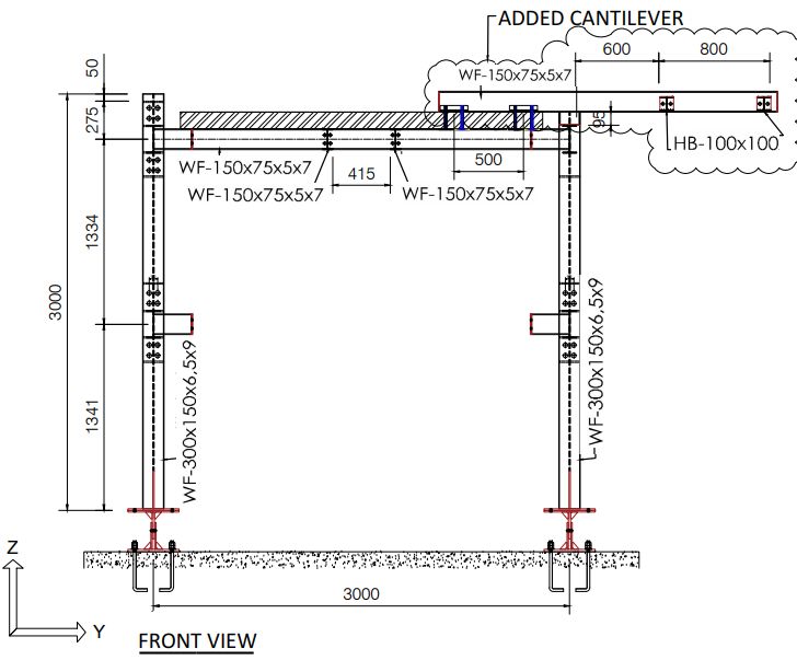
2nd Conference on Innovation in Technology (CITES 2020) IOP Publishing
IOP Conf. Series: Materials Science and Engineering 1041 (2021) 012005 doi:10.1088/1757-899X/1041/1/012005

 As part of seismic resistance structure, several research about the two systems have been conducted
for years but limited research have been reported about the dynamic test of those system. For an
economic reason, FEM modelling has been used to obtain the dynamic characteristics of several
structures. An effort has been done to get an accurate identification with development of experimental
tools to make health assessment of existing structures is more economics and the damage can be easily
detected. Eccentric mass shaker (EMS) is one of the innovative tools that can generate excitement for
a large building, which is commonly called forced-vibration tests (FVTs). In the last few decades,
dynamic tests have been used to obtain the dynamic parameters of structures [9],[10],[11,12]. The
parameters are natural frequency, mode shape, and damping ratio. The natural frequency can be used
as an indicator for detecting structural damage by examining the decrease in natural frequency [13].
 This research aims to investigate the dynamic parameters of the one storey of the RBS and EBF
system through FVTs. Eccentric mass shaker was used to induce the sinusoidal dynamic force. Two
modal parameters, natural frequency and equivalent damping ratio were obtained.

2. Materials and methods
The test was conducted on a knock down frame that was purposely designed to support the dynamic
test of two systems, the RBS and the EBF. The main frame consists of a 3m-length column, beam and
composite slab. A WF300x150x6.5x9 was used for the column which is connected to a
WF150x75x5x7 for beam on column weak axis. A composite slab with 100mm-thick was constructed
on top of metal deck at an elevation of +2682mm. RBS was connected to flange of the column by
three end plate system to ensure a rigid connection. Detail of RBS is shown in figure 2. A gap as
200mm was provided between RBS and the composite slab to prevent the composite action. The slab
was meant to provide a mass source and to locate the EMS.

 Figure 1. Top View of the Frame

 The test was conducted twice, and it was started with the RBS followed by the EBF. The RBS was
uninstalled when the second test was conducted. The EBF system was located on the elevation of
+1341mm. Detail of EBF system is shown in figure 3. The beam of EBF was constructed by
WF200x100x5.5x8 whereas the links use WF70x35x3x5. Double angle profile 2L50x50x5 was
chosen for bracing. All the steel material was used grade BJ37 where the yield strength was 235MPa.
The steel modulus of elasticity was 206MPa.

 2
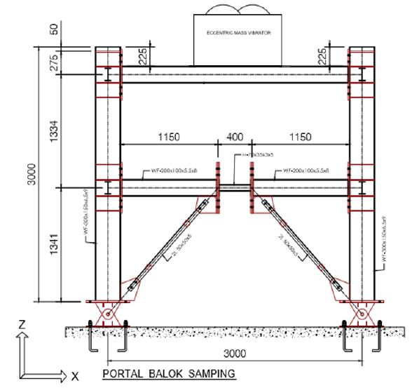
2nd Conference on Innovation in Technology (CITES 2020) IOP Publishing
IOP Conf. Series: Materials Science and Engineering 1041 (2021) 012005 doi:10.1088/1757-899X/1041/1/012005

 The load was induced by Eccentric Mass Vibrator System (EMS) MK-139-10. It was a sinusoidal
load with a frequency identical to the structure’s natural frequency. The EMS uses a two-armed drive
system that produces a single-directional force. The force exerted by the vibrator can be calculated
using the following equation:
 2
 = 2 (1)

 where F is the exerted force in Newton, MR was the eccentricity in kgm unit and is the vibrator
rotational velocity (Hz). In this test, the structure was induced by a load of 0.11625 kgm at a
frequency of 1-15 Hz. A lighter load was used to identify the elastic response of the structure. The
structural response obtained was the mode shape and the damping ratio.
 The structural response was recorded using vibrometer and accelerometer. The accelerator can
capture response in all directions, longitudinal (X), transversal (Y) and vertical (Z) meanwhile the
vibrometer only measured the longitudinal direction according to the laser shooting and at this test the
sensor was fired into the centre of the beam as shown in figure 3.

 Figure 2. Side View of the Frame and frame the picture.

 Figure 3. Detailing of EBF. Figure 4. The sensors.

3. Results and discussion

 3
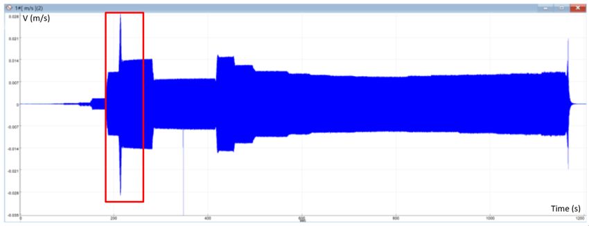
2nd Conference on Innovation in Technology (CITES 2020) IOP Publishing
IOP Conf. Series: Materials Science and Engineering 1041 (2021) 012005 doi:10.1088/1757-899X/1041/1/012005

3.1. Test Results of RBS
The structure was induced by sinusoidal forces twice. Firstly, the force frequency was increase in large
increment and secondly, the frequency was increased smoothly near to the natural frequency of the
structure. All recorded responses were the acceleration in time-domain which then were converted into
a frequency domain based on the Fast Fourier Transformation (FFT) by SIGVIEW software. The
natural frequency of the structure was obtained by looking at the peak frequency of the Frequency
Response Function (FRF). Figure 5 show on example of recording from the first test in time domain
and the results after converting to frequency domain is presented in figure. The measurement from two
test were compared and presented on Table 1. As can be seen the measurement of accelerometer and
vibrometer was very close and the average natural frequency from the test was 3.5933Hz.
 There are two methods to determine the damping ratio, using the half-power bandwidth method
and logarithmic decrement method. The results from the two methods are slightly different. The
average damping ratio from two measurements using the logarithmic and the half-power bandwidth is
3.149% and 3.219% respectively.

 Figure 5. Velocity vs time response obtained from the vibrometer in the first test

 Figure 6. FFT results in structure responses in a function of the frequency of the first test

 Table 1. The test results of RBS.
 Test Frequency (Hz) Damping Ratio (%)
 Vibrometer Accelerometer Vibrometer Accelerometer
 1st Test 3.5625 3.6168 3.553% 3.0810%
 2nd Test 3.6000 3.5939 3.553% 2.9645%
 The average 3.5812 3.6053 3.4195% 3.0138%

 4
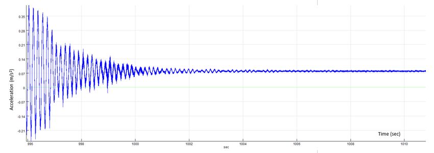
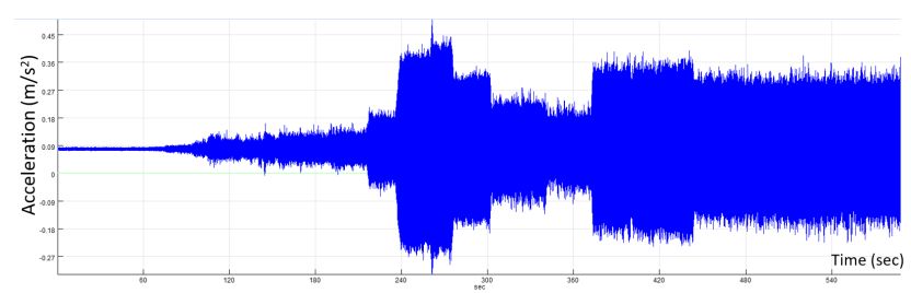
2nd Conference on Innovation in Technology (CITES 2020) IOP Publishing
IOP Conf. Series: Materials Science and Engineering 1041 (2021) 012005 doi:10.1088/1757-899X/1041/1/012005

 The dynamic FE analysis using OpenSees software was conducted for further analysis. Non-linier
beam column element was used to model the column and the beam. Concentrated plastic hinge was
assigned to represent the RBS. Properties of plastic hinge were defined by rotational spring based on
Ibarra Modified Krawinkler (IMK) [2] to describe the nonlinear behaviour of the frame.
 The dynamic load applied in the FE analysis was selected from the test which produced the
maximum displacement respond as 0.618mm. The part is shown in figure 5 which is in the red box.
The time domain forces were then converted to the frequency domain to get the frequency of the force.
The value was 3.6111Hz based on the first test, then the sinusoidal forces with similar frequency was
applied to the FE model. The displacement responds based on the FE analysis was 0.619mm
which was similar to the test results as 0.618mm. It can be concluded that the FE analysis with
OpenSees can imitate the dynamic test very well.
 Further analysis was carried out to get an inelastic respond of the RBS. The load was applied
with a frequency close to RBS natural frequency which was 3.62 Hz. This value was equal to an
eccentricity of EMS (MR) as 40 kg-m or equivalent to lateral load as 20.71kN. The result was
presented on figure 8. As can be seen, the RBS reached the plastic zone where the ultimate load
was much higher than the force applied (20.17kN). It can be explained that the RBS experienced
resonance since its natural frequency was equal to the frequency of the external forces.
 80
 Force (kN)

 60

 40

 20
 displacement (m)
 0
 -0.06 -0.04 -0.02 0 0.02 0.04 0.06
 -20

 -40

 -60

 -80

 Figure 7. The FE model of RBS Figure 8. Non- linier response of RBS based on FEA

3.2. Test Results of EBF
Similar with the first test, the EBF was test twice, under free vibration and force vibration. Figure 9
and 10 show the reading of accelerometer #1 under both conditions. The signal obtained in time
domain was then converted to frequency domain. The natural frequency and the period of the EBF
based on accelerometer #1 was 6.049 Hz and 0.165s, respectively. Using the half-power bandwidth
method, the calculation of damping ratio is presented in figure 11 which is equal to 2.06%. The
summary of natural frequency and damping ratio based on measurement from accelerometer #1, #2
and #5 and the vibrometer is listed on Table 2. The average natural frequency is around 6.09Hz
whereas the damping ratio is about 2.04%.

 5
2nd Conference on Innovation in Technology (CITES 2020) IOP Publishing
IOP Conf. Series: Materials Science and Engineering 1041 (2021) 012005 doi:10.1088/1757-899X/1041/1/012005

 Figure 9. Accelerationvs time from accelerometer #1, under free vibration

 Figure 10. Accelerationvs time from accelerometer #1, under forced vibration

The FE analysis using OpenSees was carried out as a comparison. According to the experiment, the
EBF was categorized as a flexural link. Steel02 was selected for steel material which is a uniaxial
Giuffre-Menegotto-Pinto model with isotropic strain hardening. Truss element was assigned for
bracing. Beam and column used the NonlinearBeamColumn element that assumes plastic deformation
to be distributed along the element. Link was defined with BeamWithHinges command, where the
plasticity is concentrated at the end of link.

 The damping ratio:

 − 6.2 − 5.95
 Magnitu = =
 de 2 2 6.04938
 (Linear = 0.0206 = 2.06%
 Scale)

 Magnitude of the frequency response function

Figure 11.The calculation of damping ratio based on accelerometer #1 under free vibration conditions
using the Half-Power Bandwidth Method.

 6
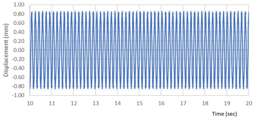
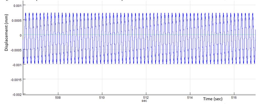
2nd Conference on Innovation in Technology (CITES 2020) IOP Publishing
IOP Conf. Series: Materials Science and Engineering 1041 (2021) 012005 doi:10.1088/1757-899X/1041/1/012005

 Table 2. The test results of EBF.
 Frequency (Hz) Damping Ratio (%)
 Accelerometer #1 6.049 2.06%
 Accelerometer #2 6.111 2.04%
 Vibrometer 6.111 2.04%

Similar loading condition as applied on the experiment was used. The excitation with a light load of
0.11625 kgm was induced with gradually increasing frequency. The structural response was in the
elastic stage. The displacement reading from the vibrometer was used to compare the FEA and the
experiment. Figure 12 shows the vibrometer response where the minimum and the maximum
displacement was 0.73 mm and 0.98 mm, respectively thus having a displacement of 0.855 mm. The
FE results is shown in figure 13. The displacement obtained is almost similar to the experiment which
is 0.853 mm.

 Figure 12. Displacement vs Time from vibrometer response

 Figure 13. Displacement vs Time from FE Analysis

4. Conclusion
The force vibration test can be conducted by using the EMS. The linier dynamic response obtained
from the test are the natural frequency and the damping ratio. The natural frequency of the RBS steel
frame is about 3.614 Hz which is similar to the FE analysis as 3,623 Hz. Meanwhile the damping ratio
is 3.149%. Similar displacement response was attained from the test and the FE analysis.
 The natural frequency of the structure gain from the test is around 6 – 6.133 Hz, while the FE
analysis result is 6.13 Hz. Moreover, the damping ratio based on vibrometer and accelerometers
measurements is between 2.04 – 2.06%. The elastic displacement obtained from the experiment is
0.855 mm which is almost identical to the displacement from the FE analysis as 0.853 mm. The

 7
2nd Conference on Innovation in Technology (CITES 2020) IOP Publishing
IOP Conf. Series: Materials Science and Engineering 1041 (2021) 012005 doi:10.1088/1757-899X/1041/1/012005

dynamic response conducted using FE software OpenSEES is potent in modeling a steel RBS and
EBF structure with harmonic excitation.
Acknowledgement
Universitas Indonesia supports this work through Hibah PUTI, contract number: NKB-
1186/UN2.RST/HKP.05.00/2020

References
[1] Sophianopoulos D S and Der A E 2011 Parameters affecting response and design of steel
 moment frame reduced beam section connections: An overviewInt. J. Steel Struct.11 133–44
[2] Lignos D G and Krawinkler H 2011 Deterioration Modeling of Steel Components in Support
 of Collapse Prediction of Steel Moment Frames under Earthquake Loading J. Struct. Eng.137
 1291–302
[3] Kildashti K, Mirghaderi R and Kani I M 2012 The Efficiency of Reduced Beam Section
 Connections for Reducing Residual Drifts in Moment Resisting Frames Open J. Civ. Eng.02
 68–76
[4] Deri A E and Sophianopoulos D S 2015 Parametric Analysis and Optimization of Reduced
 Beam Section Steel Frame Connections Conference: 7th European Conference on Steel and
 Composite Structures at: Naples, Italy
[5] Sofias C E, Kalfas C N and Pachoumis D T 2014 Experimental and FEM analysis of reduced
 beam section moment endplate connections under cyclic loading Eng. Struct.59 320–9
[6] Sophianopoulos D S and Deri A E 2017 Steel beam-to-column RBS connections with
 European profiles: I. Static optimization J. Constr. Steel Res.139 101–9
[7] Berman J W and Bruneau M 2007 Experimental and analytical investigation of tubular links
 for eccentrically braced frames Eng. Struct.29 1929–38
[8] Kasai K and Popov E P 1986 Cyclic Web Buckling Control for Shear Link Beams J. Struct.
 Eng.112 505–23
[9] Morassi A and Tonon S 2008 Dynamic Testing for Structural Identification of a Bridge J.
 Bridg. Eng.13 573–85
[10] Conte J P, He X, Moaveni B, Masri S F, Caffrey J P, Wahbeh M, Tasbihgoo F, Whang D H
 and Elgamal A 2008 Dynamic Testing of Alfred Zampa Memorial Bridge J. Struct. Eng.134
 1006–15
[11] Hogan L S, Wotherspoon L, Beskhyroun S and Ingham J 2016 Dynamic Field Testing of a
 Three-Span Precast-Concrete Bridge J. Bridg. Eng.21 06016007
[12] Setareh M and Gan S 2018 Vibration Testing, Analysis, and Human-Structure Interaction
 Studies of a Slender Footbridge J. Perform. Constr. Facil.32 04018068
[13] Halling M W, Muhammad I and Womack K C 2001 Dynamic Field Testing for Condition
 Assessment of Bridge Bents Struct. Eng.127 161–7

 8
You can also read