RSA-1.0 INSTALLATION INSTRUCTIONS - Remote Serial Adaptor
←
→
Page content transcription
If your browser does not render page correctly, please read the page content below
INSTALLATION INSTRUCTIONS

       RSA-1.0
        Remote Serial Adaptor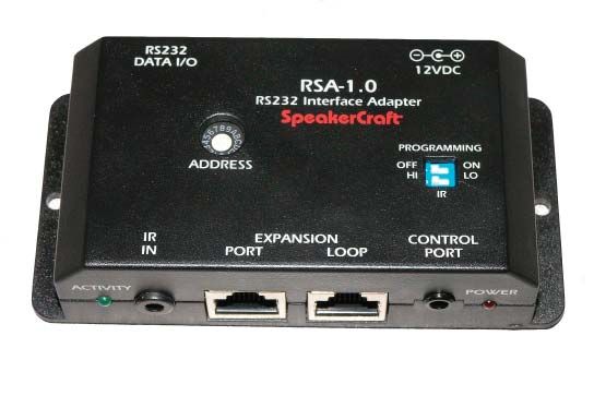
RSA-1.0 Installation Instructions                                                                                                                  Page 2

INTRODUCTION
The SpeakerCraft RSA-1.0 Remote Serial Adaptor provides control of RS232 compatible devices from SpeakerCraft MZC-66 and
MZC-88 A/V Amplifier/Controllers. It connects to an MZC rear panel Expansion Terminal and is triggered by EZ-Pad Button
presses or remote EZ-Code IR commands (when used to control an MZC-66 or 88). The RS232 Commands are programmed
into MZC Projects using EZ-Tools Programming Software. RS232 commands are stored in the EZ-Tools Command Library and
programmed to keypad buttons using a similar procedure to programming IR commands. New RS232 commands, of up to
100 characters each, can be added to the Library in EZ-Tools via ASCII or HEX data entry.

Up to 16 RSA-1.0s can be used in a single system by setting each RSA to a unique device Address. A data buss can be created
to ‘daisy chain’ the RSAs for ease of installation and connection.

RSA-1.0 FEATURES

1. RS232 DATA I/O - DB9M terminal connects to the de-
                                                                                             ASW1                                          SW1:1
   vice being controlled via RS232 using a DB9 cable.
                                                                                                               Rear View

2. ADDRESS SWITCH - 16 position rotary switch, sets de-                                1         2                                             3
   vice address allowing up to 16 RSA’s to be used in a single
                                                                                                                 Top
   system.
                                                                                   RS232
                                                                                  DATA I/O                                                 12VDC
                                                                                                                   U2           U5
3. 12VDC POWER JACK - 2.1mm coaxial jack connects to                                                                     RSA-1.0
                                                                                       J1
   a SpeakerCraft PS-1.0 Power Supply for power.                                                                                    J6
                                                                                                               RS232 Interface Adapter
                                                                                                                  U4    U3
                                                                                             ASW1
                                                                                               7     89A          SpeakerCraft             ®
                                                                                                                                                     U1
                                                                                  U7

                                                                                              23 6
                                                                                                       BCD
                                                                                                45
                                                                                                EF 1
                                                                                                  0                                  PROGRAMMING
                                                                 2.125“                           J2
4. PROGRAMMING SWITCH - Two-position switch gets set                                                                       J3        OFF SW1:1 ON                     4
                                                                                             ADDRESS
                                                                                     J5                                               HI              LO
   to ON position for updating the firmware from EZ-Tools.                   U6                                                                 J4
                                                                                                                                               IR                     5
                                                                             D4                                                                            D5
5. IR HI/LO SWITCH - Two-position switch sets the IR                                 IR
                                                                                     IN
                                                                                                        EXPANSION
                                                                                                     PORT       LOOP
                                                                                                                                       CONTROL
                                                                                                                                         PORT
   IN level. Set to HI when connected to a high IR output
   device, (12V; P-P) set to LO when connected to a low
   output device, (5V; P-P).                                                11 10                          9               8                   7           6

6. POWER LED - Red LED illuminates when RSA has DC
                                                                                             ASW1                                          SW1:1
   power and completes its internal initialization.
                                                                   1“     ACTIVITY                                                                    POWER

7. CONTROL PORT - 4-circuit, 3.5mm mini-jack connects to
   PC running EZ-Tools for RSA programming and firmware                                                          Front
   updates.                                                                                                       4.3”

                                                                                                                                                           Figure 1
                                                                                                                                                           RSA-1.0 Features
8. EXPANSION LOOP - RJ45 jack primarily used to connect to the Expansion Port on additional RSA-1.0(s) when mul-
   tiple RSA-1.0’s are used to control multiple RS232 devices in a single system. The Expansion Loop and Expansion Port
   jacks are parallel. Up to 16 RSA-1.0’s can be used in a single system.

9. EXPANSION PORT - RJ45 jack primarily used to connect to the Expansion Port or Loop on a SpeakerCraft MZC-66
   or MZC-88. This connection receives control data from the MZC via RS485. RS232 commands are configured in the MZC
   using EZ-Tools.

10. IR IN - 3.5mm mini jack receives SpeakerCraft EZ-Code IR commands from an IR control system. These commands are
    converted to RS232 commands as associated in EZ-Tools. This jack only functions when the special IR to RS232 Control
    Interfacing Firmware has been programmed into the RSA.

11. ACTIVITY INDICATOR - Green LED flashes to indicate activation of internal command data.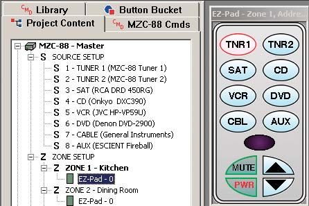
RSA-1.0 Installation Instructions Page 3
To RS232 To RS232
Controlled Controlled
Device Device
DB9 DB9
Cable PS-1.0 200mA Cable PS-1.0 200mA
Power Supply Power Supply
RS232 RS232
DATA I/O 12VDC DATA I/O 12VDC
U2 U5 U2 U5
RSA-1.0 RSA-1.0
J1 J1
J6
RS232 Interface Adapter J6
RS232 Interface Adapter
U4 U3 U1 U4 U3 U1
ASW1
F 012
SpeakerCraft ®
ASW1
F 012
SpeakerCraft ®
U7 U7
BCDE
BCDE
3456
3456
78 A 789A
9
PROGRAMMING PROGRAMMING
J2 J3 OFFSW1:1ON
J2 J3 OFFSW1:1ON
ADDRESS ADDRESS
J5 HI LO
J5 HI LO
U6 J4
IR U6 J4
IR
D4 D5 D4 D5
IR EXPANSION CONTROL IR EXPANSION CONTROL
IN PORT LOOP PORT IN PORT LOOP PORT
MZC-66
or
MZC-88 RJ45
Controller RS485
Interface
Cables
Figure 2
Typical RSA-1.0 Application
INSTALLATION
When all system components are installed in a central equipment rack or closet, the RSA-1.0(s) should be mounted in a place
that provides easy access should reprogramming or service be necessary. The plastic flange extensions and mounting holes
allow vertical installation on a cabinet side or equipment room wall.
The CAT-5 connections between an MZC-66/88 and a RSA-1.0 are RS485 protocol, so the runs can be fairly long. Typical
RS-485 TX/RX, (transmit/receive) allows up to 1000 feet between devices. When using multiple RSA’s, the TOTAL cable length
from the MZC to the LAST RSA should not exceed this specification.
The DB9 connections between the RSA-1.0(s) and the device(s) being controlled are RS232 protocol which has a limitation of
about 50 feet between devices. For best performance try to install the RSA-1.0(s) as close to the device(s) being controlled as
possible.
When using multiple RSA’s, it is recommended that each be labeled with the device brand, type (DVD player, Server, etc) and
model number to assist in servicing and troubleshooting the system when necessary.
CONNECTIONS
NOTE: The RSA-1.0 has a DTE pinout. If the device being controlled has a DCE pinout, a pass-through cable, (pin to
pin), should be used. If the device being controlled also has a DTE pinout, then a Null Modem Cable should be used.
1. Using a properly terminated CAT-5 cable (pass-through, pin to pin configuration) connect the Expansion Loop on a
SpeakerCraft MZC-66/88 to the Expansion Port on a RSA-1.0. (Refer to Figure 2)
2. Using a properly configured DB9 cable to connect the RS 232 DATA I/O Port on the RSA-1.0 to an appropriate RS 232
Data I/O Port on the device being controlled. (Refer to Figure 2)
3. If using multiple RSA-1.0’s using a properly terminated CAT-5 cable (pass-through, pin to pin configuration) connect the
Expansion Loop on a RSA-1.0 to the Expansion Port on the next RSA-1.0. (Refer to Figure 2)
4. Using properly configured DB9 cables (pass-through, pin to pin configuration) connect the RS 232 DATA I/O Ports on
the RSA-1.0’s to the appropriate RS 232 Data I/O Ports on the devices being controlled. (Refer to Figure 2)
5. When all other connections have been made and the system is ready for programming/operation, connect a
SpeakerCraft PSA-1.0 12VDC 200mA Power Supply to the 12VDC Power Jack on each RSA-1.0. (Refer to Figure
2)
RSA-1.0 Installation Instructions                                                                                Page 4

CONFIGURATION

Configuring a single RSA-1.0 application is simple. Set the Address Switch to ‘0’. (Be sure to select Address ‘0’ when Adding
An Expansion Device in EZ-Tools Setup.)

Configuring multiple RSA-1.0s is similar in a way to routed infrared. With routed IR, when a button is pressed on a keypad
or remote, to control for example a specific Satellite Receiver in a system with multiple Satellite Receivers, the IR command is
routed by the Control System to the specific IR output for that Satellite Receiver, allowing selective control of multiple same-
brand, same-model devices. The same is true when using multiple RSA-1.0’s. When a button is pressed on a keypad or
remote (specifically programmed to control a MZC-66/88) the Control System (MZC-66/88) will output a control command
via the Expansion Loop that will ‘look’ for a specific RSA Address. When an RSA with the proper Address is located, that RSA
will interpret the incoming control command and output the appropriate RS232 command to the device being controlled.
All other RSA’s on the Expansion Loop Bus, set to a different Address will ignore the command. This allows selective RS232
control of multiple same-brand, same-model devices or control of a variety of devices from different manufacturers.

1. When using one RSA-1.0, set the Address Switch to ‘0’.

2. When using multiple RSA-1.0’s set the Address Switch on each RSA-1.0 to a different address. Up to 16 different addresses
   can be configured.

    When using multiple RSA-1.0’s keep a written record of each RSA’s Address Switch setting and the device it is intended to
    control. This information will be critical during programming.

PROGRAMMING

The initial release of the RSA-1.0 will only allow programming and interfacing with SpeakerCraft MZC-66/88 Multi-Zone
Controllers. The following Programming Instructions detail the steps required to program a RSA-1.0 for use with MZC-66/88.
Please visit the SpeakerCraft web site, www.speakercraft.com for updates on additional uses of this product, including IR to
RS232 control interfacing.

Programming an RSA-1.0 for use in a MZC System is similar to the normal programming procedure for associating System
commands in Events Setup or configuring Source Commands in Zone Setup. For Events Setup, the RSA RS232 commands
can be associated with a System Turning ON, System Turning OFF, Zone Turning ON, Zone Turning OFF or Doorbell Event
in the same way that MZC Commands or Source IR commands are programmed. In Zone Setup, RSA RS232 commands can
be configured to be output from the MZC when initiated by a keypad button press as a single command or part of a macro.
Programming an RSA-1.0 does require that RS232 commands have been stored in the CMD Library by Brand, Component
and Model. See Section: Creating RS232 Commands for additional information. To program a MZC Project using an RSA-1.0
with existing RS232 commands:
1. Open an existing or create a new EZ-Tools Project for
     MZC-66/88.

2. Left click the Project Content Tab so MZC-66/88 Stand-
   alone is highlighted. (In expanded systems with multiple
   MZC’s, MZC-66/88 Master should be highlighted.)

3. Right Click MZC Standalone/Master. Highlight Add
   Expansion Device in the pop-up window.

4. Left Click RSA-1.0 in the second pop-up window. (Refer
   to Figure 3) The Expansion Device Setup Window will
   appear. NOTE: An RSA-1.0 can also be added by right
                                                                                                    Figure 3
   clicking the Expansion Devices icon at the bottom of the                                         Adding an RSA-1.0 to a MZC Project
   Project Content Window. Right click Expansion Devices,
   roll the mouse over the pop-up and left click RSA-1.0.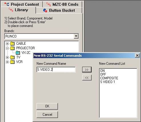
RSA-1.0 Installation Instructions Page 5
5. Select an Address from the Address pull-down. (Refer to
Figure 4) If using only one RSA-1.0 use the default of ‘0’. If
using multiple RSA-1.0’s, set each to a different address.
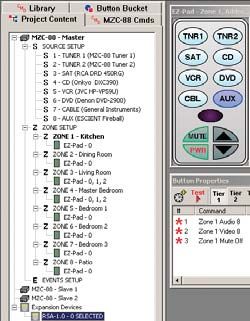
6. Left click OK in the Expansion Device Setup Window to
set the Address. An RSA-1.0 icon will appear at the bottom
of the Project Content Window under Expansion Devices
as RSA-1.0-0 (assuming Address ‘0’ was selected). If mul-
tiple RSA-1.0s are added, they will all appear and each will
indicate its Address, RSA-1.0-0; RSA-1.0-1; RSA-1.0-2; etc.
as shown in Figure 5.
7. In the Project Content Window, left click the EZ-Pad in Figure 4
the Zone that is going to be programmed to send RS232 Selecting an RSA-1.0 Address
commands from the RSA-1.0. (Zone 1, EZ-Pad-0 as shown
in Figure 6.) The EZ-Pad selected will appear on screen.
8. Left click the button on the EZ-Pad that is going to be
programmed to send RS232 commands via the RSA-1.0.
The button will highlight in blue, and the Button Proper-
ties Window will appear, if not already on screen.
9. In the Project Content Window, left click the RSA-1.0 that
is going to control the device selected on the EZ-Pad
in Step 8 above, (in this case AUX, which is an Escient
FireBall). The word SELECTED will appear after the RSA-
1.0 icon to indicate that the RSA has been selected for Figure 5
programming. If multiple RSAs are being used in a system, Multiple RSA-1.0 Addresses
this will indicate which RSA has been selected.
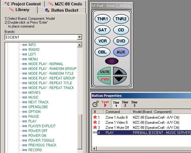
10. Left click the CMD Library Tab to bring the IR/RS232 Com-
mand Library to the front.
11. In the Brands text box, type in the name of the brand
to be programmed, in this case Escient. (The pull-down
can also be used as well as typing in ‘E’ and scrolling to
Escient from the beginning of the ‘E’s’ using the arrow
down key.)
12. Double left click the type of component being controlled,
DVD player, CD changer, etc. or in this case, Music Server.
Figure 6
If a single model is available under the component se- Select EZ-Pad
lected, the sub-directory will open a list of commands. If
multiple model numbers are available, double left click the
model number for the device being controlled to open
the command list.
13. Scroll through the list to find the RS232 Commands.
RS232 Commands are ‘prefixed’ with a blue ‘1010’. If
no RS232 commands are available from the Command
Library, see section: Creating RS232 Commands.
14. Double left click the desired RS232 command. The com-
mand will appear in the Button Properties Window. (Refer
to Figure 8) If there are commands already associated
with the button being programmed, the RS232 com- Figure 7
mand will appear at the bottom of the list. The command EZ-Pad Button and RSA-1.0 SelectionRSA-1.0 Installation Instructions Page 6
can be moved up in the list by dragging and dropping
the command to a different position. Be sure moving
commands in the list does not adversely affect existing
functionality.
15. The RS232 command line in the Button Properties Win-
dow will show the blue ‘1010’ icon to indicate an RS232
command, the function, brand, component and ‘RSA-1.0
Add. 0 RS232’ indicating that the command has been
properly associated with the RSA-1.0. If an EZ-Pad button
press does not properly execute control functions, this is a
good place to look in troubleshooting to confirm Zone/
EZ-Pad/Button/RSA-1.0/RS232 command configuration.
See section: Troubleshooting for additional information.
16. Repeat steps 1-6 above to add RSA-1.0s.
17. Repeat steps 7-14 to program EZ-Pads with RS232 com-
mands for RSA-1.0s. Figure 8
Programmed RSA-1.0 RS232 Command
ADDING NEW RS232 COMMANDS TO THE COMMAND LIBRARY
New RS232 Commands can be quickly added to the EZ-Tools CMD Library. ASCII text strings of up to 100 characters can be
added when either the ASCII or HEX code is known. Additionally, Baud Rate, Data Bits, Parity, Stop Bits, Character Delay,
Response Length and Response Timeout can be set to assure proper performance of these control commands. ASCII, HEX
and other code parameters can typically be found in product manuals or on manufacturers web sites. It may be necessary on
occasion to contact a particular manufacturer’s tech support to get this information.
In some cases, the EZ-Tools CMD Library will already have IR codes or possibly some RS232 Commands for a particular Brand,
Component and Model, and all that need be done is to add a couple of RS232 commands. In other cases, the Brand, Com-
ponent and Model for which RS232 commands are required may not be in the CMD Library. Start with the appropriate step
for the specific command(s) being added.
1. With EZ-Tools running, open the project for which the new RS232 Commands are required. (If not ready to program a
specific project, open any EZ-Tools project.)
2. Left click the CMD Library Tab.
3. If the Brand name does not already exist, right click within the Brands space and left click “New Brand”. Type in the
new brand name and click OK.
4. Right click the empty space below the brand name and left click “New Component”. Type in the new component
name (i.e. Projector) and click OK.
5. Right click the new (Projector) folder and left click “New Model”. Type in the new model name (the model # of the com-
ponent or it’s remote, i.e., VX-2c) and click OK.
6. Right click the new model # folder (i.e., VX-2c). Go to “New Commands” and left click “RS232 Serial Commands”.
Type in command name (i.e., ON) and left click right arrows (>>) to put the name in the New Command List. Type in a
complete list of command names (i.e., ON, OFF, COMPOSITE, S VIDEO 1, S VIDEO 2, etc.) as needed. (Refer to Figure
9)
7. When all new command names have been added to the New Command List, click OK.
8. The Command Properties Window will open automatically, with the first new command already placed in the
Command Name field. (i.e. ON) (Refer to Figure 10)RSA-1.0 Installation Instructions Page 7
9. Left click Modify in the Com Port Settings box, to make
any changes necessary to: Baud Rate, Data Bits, Parity
and Stop bits, per the manufacturer’s protocol. The
Serial Port Settings pop-up will appear. Make necessary
changes and click OK. (Refer to Figure 10)
10. In the Command/Data Editor box, left click either
the ASCII or HEX field under “01” depending upon
which data, ASCII or HEX will be used to create the new
command. Type in the command string, one character
per box, up to 100 characters.
11. In the Advanced Settings box select a Character
Delay, from 0 (no delay) to 50 mS (milliseconds) if
needed, to be inserted between characters when
command strings are being sent.
12. In the Response Settings box, select the appropriate
Response Length from 0 to 100 Characters to confirm Figure 9
that the command string has been properly sent, received Adding New RS232 Command Names
and executed.
13. In the Response Settings box, select the appropriate
Response Timeout from 0.0 to 10.0 seconds. This will
determine the amount of time the RS232I/O Port will stay
‘open’ waiting for a response from the controlled device.
14. When all Command Properties for the specific command
being edited have been made, click OK. The command
will be added to the CMD Library and will be designated
with a “1010” icon. The next New Command will
automatically come up in the Command Properties
Window. Typically, a manufacturer will use the same
settings for baud, Data Bits, etc., so all that need be done
is to type in the ASCII or HEX code for the individual
commands. When all New Commands have been Figure 10
formatted, the Command Properties Window will close Entering RS232 Command Properties
and all commands will be listed in the appropriate CMD
Library List. (Refer to Figure 11)
Once RS232 Commands have been added to the CMD
Library, they are available for use in any EZ-Tools project when
programming RS232 codes is required.
Figure 11
New RS232 Commands in Command LibraryRSA-1.0 Installation Instructions Page 8
SPECIFICATIONS
Dimensions: 4.3”L x 2.125”W x 1”H
Power Requirement: 12V DC; 200mA (SpeakerCraft PS-1.0 Power Supply)
Connectors
Power: 2.1mm coaxial jack
IR In: 3.5mm mini jack
Network: 2 x RJ45
RS232: DB9M
Control Port: 3.5mm mini jack (4-circuit)
RS232 Parameters
Baud Rate: 300, 1200, 2400, 4800, 9600, 19200, 38400, 57600 Selectable
Data Bits: 7, 8 Selectable
Stop Bits: 1, 2 Selectable
Parity: None, Odd, Even Selectable
Command String: 100 Characters Max
Character Delay: 0-50mS
Response String: 0-100 Characters
Response Timeout: 0.0-10.0 Seconds
Transmission Length
Network (RS485): 1000’ Max
RS232 Data I/O: 50’ MaxRSA-1.0 Installation Instructions Page 9 LIMITED 2-YEAR WARRANTY SpeakerCraft Inc. warrants to the original retail purchaser only that this SpeakerCraft product will be free from defects in materials and workmanship for a period of two years, provided the product was purchased from a SpeakerCraft Authorized Dealer. Defective products must be shipped, together with proof of purchase, prepaid insured to the SpeakerCraft Authorized Dealer from whom they were purchased, or to the SpeakerCraft factory at the address listed on this installation instruction manual. Freight collect shipments will be refused. It is preferable to ship this product in the original shipping container to lessen the chance of transit damage. In any case, the risk or loss or damage in transit is to be borne by the purchaser. If, upon examination at the Factory or SpeakerCraft Authorized Dealer, it is determined that the unit was defective in materi- als or workmanship at any time during this warranty period, SpeakerCraft or the SpeakerCraft Authorized Dealer will, at its option, repair or replace this product at no additional charge, except as set forth below. If this model is no longer available and cannot be repaired effectively, SpeakerCraft, at its sole option, may replace the unit with a current model of equal or greater value. In some cases where a new model is substituted, a modification to the mounting surface may be required. If mounting surface modification is required, SpeakerCraft assumes no responsibility or liability for such modification. All replaced parts and product become the property of SpeakerCraft Inc. Products replaced or repaired under this Warranty will be returned to the original retail purchaser, within a reasonable time, freight prepaid. This Warranty does not include service or parts to repair damage caused by accident, disaster, misuse, abuse, negligence, inadequate packing or shipping procedures, commercial use, voltage inputs in excess of the rated maximum of the unit, or service, repair or modification of the product which has not been authorized or approved by SpeakerCraft. This Warranty also excludes normal cosmetic deterioration caused by environmental conditions. This Warranty will be void if the Serial Number on the product has been removed, tampered with or defaced. This Warranty is in lieu of all other expressed warranties. If the product is defective in materials or workmanship as warranted above, the purchaser’s sole remedy shall be repair or replacement as provided above. In no event will SpeakerCraft be liable for any incidental or consequential damages arising out of the use or inability to use the product, even if SpeakerCraft Inc. or a SpeakerCraft Inc. Authorized Dealer has been advised of the possibility of such damages, or for any claim by any other party. Some states do not allow the exclusion or limitation of consequential damages, so the above limitation and exclusion may not apply. All implied warranties on the product are limited to the duration of this expressed Warranty. Some states do not allow limitation on the length of an implied warranty. If the original retail purchaser resides in such a state, this limitation does not apply. SpeakerCraft offers a variety of accessories to make your installation of this and other SpeakerCraft products easy, econom- ical, and professional. Contact your authorized SpeakerCraft Dealer for more information. For technical inquires, please call 1-800-448-0976 or e-mail us at techsupport@speakercraft.com. We are available to assist you every weekday, except holidays, between the hours of 7:00 a.m. and 5:00 p.m. PST.
RSA-1.0 Installation Instructions            Page 10

  940 Columbia Avenue, Riverside, CA 92507
  (800) 448-0976 Fax (951) 787-8747
  www.speakercraft.com                           LIT07105
You can also read