Variable speed controller for pumps - nastec.eu
←
→
Page content transcription
If your browser does not render page correctly, please read the page content below
Variable speed
controller for pumps

nastec.eu
VASCO - VAriable Speed COntroller
is a purpose-built family of variable frequency
drives, designed to control and protect pumping
systems based on changing pump speed.

Maximum
compactness
VASCO - VAriable Speed COn-     The device also provides mo-       recording running hours
troller units are extremely     tor protection and monitoring,     and loggings errors and
compact and, connected to       such as:                           alarms reported by the
any pump on the market, will                                       system
manage the operation of the       protection against overload
pump to maintain a constant       and dry running                  controlling a second or
desired physical dimension                                         third pump at constant
(such as pressure, flow, tem-     indication of input current      speed DOL (DOL: Direct
perature or other). The pum-      and supply voltage               On Line)
ping system runs only at the
speed necessary to meet the       integrated soft start and soft   connect to other devices to
user’s requirements, ensuring     stop functions, extending the    get combined operation
energy savings and extending      life of the system and redu-
the life of the system.           cing peak absorption
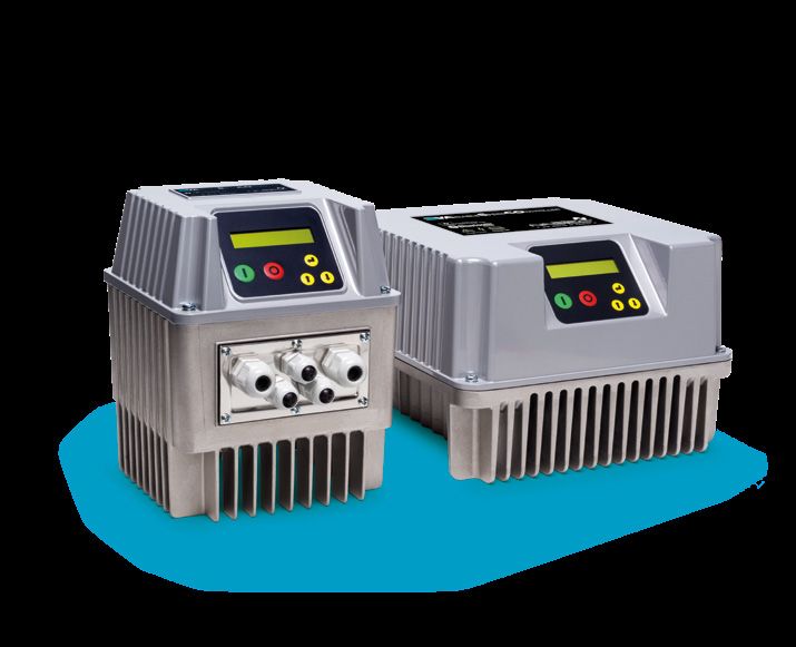
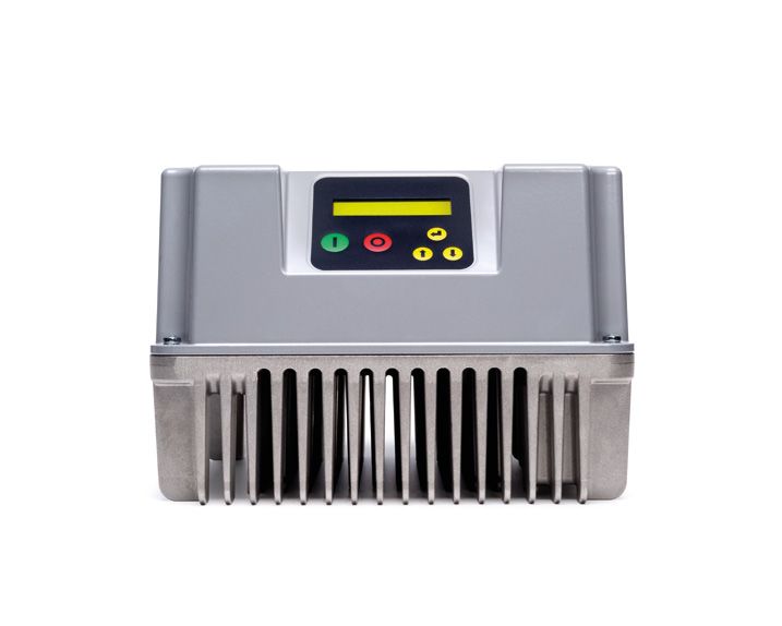
From water supply for domestic, irrigation,
commercial and industrial applications, to heating
and air conditioning, from filtering to pressure
washing, the VASCO - VAriable Speed COntroller
range perfectly fits any new or existing application
ensuring:
  energy and cost saving            longevity of pumping system
  simplified installation           greater reliability

The compact body is con-          The IP55 degree of protection    The illuminated liquid crystal
structed entirely of aluminium,   makes it possible to install     display ensures that it is easy
making he device extremely        the device virtually anywhere,   to operate, and a buzzer pro-
solid, lightweight and easily     including humid and dusty en-    vides an immediate indication
cooled, adding to the unit’s      vironments.                      of alarm.
versatility.
The installation is simple
and intuitive, requiring
just a few quick steps
   Power connection.

   Connection to the pump.

   Connection to the sensor, located wherever in
   the piping you want to maintain the desired
   constant physical dimension (pressure, flow,
   liquid temperature, etc.).

   Set device to configure the pump to the sy-
   stem and the desired performance.

When first powering the device, a quick initial wi-
zard is required for complete configuration of the
drive. Additional parameters can be configured la-
ter by entering three different setting levels:

   End user level. The only level which can be ac-
   cessed without a password. It allows the user to
   monitor electrical and hydraulic parameters and
   the status of the inverter and pump.

   Installer level. In this level the installer can
   configure the pump system to the characte-
   ristics of the hydraulic system. A password is
   required.

   Advanced level. This level allows the electrical
   configuration of the inverter according to the
   pump. Another password is required.
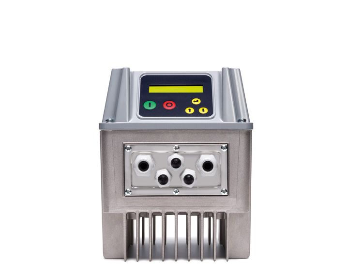
It can be installed directly
on the motor or directly
to the wall with a supplied
installation kit

Motor kit
The inverter is cooled by the motor cooling fan.
Motor kit consists of 4 special clamps (or flange
adapter) to secure the device to the motor fan
cover (or motor feet).

Wall kit
The unit is cooled by an external cooling fan at-
tached to the inverter radiator. A special metal
bracket is supplied for device to be mounted on
the wall.
Software implemented in each drive
of VASCO - VAriable Speed COntroller range
is the result of a long-time experience in solving
customer requests and constantly following
new drive applications.
Minimum motor frequency
                                     Hz
                                                              PI Control
This parameter prevents motor
operation below a certain fre-                                                                                Max motor freq.
quency, thus avoiding dama-
ge to the thrust bearing of the                                                   Ramp down time
submersible motors.
                                                        Ramp up time

Minimum motor frequency                                                                     Stop delay
                                                                                                              Freq. min. control
ramp
                                                                             Control ramp
                                                                                                              Min motor freq.
Motor can accelerate from 0 to
the minimum motor frequency
                                              Ramp f min mot.                               Ramp f min mot.
following a very fast ramp and
then go through a slower ramp.
                                                                                                                             Sec.

Intelligent stop of pump              Hz                                                                      Pressure
at no flow condition
                                              Delta control                                                   Set value

Below minimum control fre-
quency, the inverter gradual-
ly reduces the pump speed
                                                                     Stop delay               Control ramp
while monitoring the pressure       Freq.
                                    min.
transducer signal. If this value    control
is maintained close to the set
pressure, the inverter will redu-
ce the output frequency until       Min.
stopping the pump definitely.       mot.
                                    freq                                                                                  sec

Maximum and minimum
alarm pressure

When the pressure rises abo-
ve a certain settable pressu-
re value, the inverter will stop
the pump to prevent damage
to the hydraulic components
in the system. Similarly, if the
pressure drops below a certain
pressure an alarm is triggered
and the pump is stopped.
Loss compensation
300 m
proportional to the water flow
H
If the pressure sensor is placed
Pressure
near the pump, with the incre- sensor
ase in flow the pressure value
at the furthest outlet is lower
4 bar
than the set pressure. It is pos-
sible to vary the set pressure Compensation (1 bar)
in proportion to the frequency
to compensate pressure loss in Set value (3 bar)
the pipes.
Min. mot. freq. Max. mot. freq.
Q
Dry running alarm V/f programmable
via cosphi value curve
If the pump runs dry, its cosphi Device offers two different
value drops below a settable methods of torque control (vol-
cosphi value, and the inverter tage) versus pump speed (fre-
stops the pump after 3 seconds. quency):
The device will try to make 5 at- • constant torque (linear V/f)
tempts every 10, 20, 40, 80 and • quadratic variable torque
160 minutes, after which it will (squared V/f)
trigger an alarm and stop the For centrifugal pumps, energy
pump if the condition persists. savings can be obtained by se-
lecting squared V/f control.
Settable carrier frequency
between 2.5, 4, 6, 8, 10 kHz
If inverter controls a submersi-
ble pump with long cables, it is
possible to decrease the carrier
frequency value to ensure lon-
ger motor life.In addition to constant pressure control,
VASCO - VAriable Speed COntroller allows
other control modes such as fixed frequency,
constant flow, constant temperature.
Constant pressure
The inverter controls the pump H
speed to maintain constant
pressure at a set point inde- 4
7
pendent of the water demand 1
in the system.
5
In a hydraulic system equipped
with inverter, the standard pres-
2 3 6 5
sure tank is replaced by a smaller
tank which functions to maintain 35HZ 40HZ 50HZ 1 Inverter 5 Valve
the set pressure in the system 2
3
Pump
No return valve
6 Pressure transducer
7 Power supply
when the pump is stopped. Q 4 Pressure tank
Constant pressure 2 values
By selecting the constant pres-
sure 2 values control mode, in
irrigation systems, only one 3 bar 5 bar
pump can serve two zones
with different pressure sets. It 2
is possible to switch the two
values by acting on a digit in-
put contact.
1
Fixed frequency 2 values
If it is not necessary to opera-
te at constant pressure but is
required to select 2 different
pump speeds, by selecting
fixed frequency 2 values con-
trol mode it is possible to swi-
tch the 2 values by acting on a
digit input contact.Constant temperature The control method at constant temperature is used to main- tain the temperature of the pumped fluid to vary the ther- mal load. This control system is used in air conditioning or re- frigeration and cooling towers. In this latter case, for example, the temperature measured by a sensor in the return water is kept constant. External frequency In some application, it is cho- sen to change the frequency of Hz the pump by using an external signal coming from a trimmer or a PLC. In this case, after se- lecting the External Frequency control mode, it is enough to connect an input signal 4-20 mA or 0-10V, proportional to the desired frequency, to the AN4 analogue contact. Constant flow By selecting the constant flow for filtering the pumped fluid control mode and using a flow in which the obstruction of the transducer, it is possible to filter would lead to a progres- control the flow of the pum- sive reduction of the flow rate ped liquid to vary the system if it is not compensated by an condition. This control mode is increasing of the pump speed. used, for example, in a system
Unmatched user experience
Thanks to Nastec NOW app it is possible to communicate with all
Nastec SMART Bluetooth® devices in order to:
Monitor multiple operating Create reports with the pos-
parameters simultaneously sibility of adding notes and
on the wide, high defini- images, and email or store
tion, coloured screen of your them in the digital archive.
smartphone or tablet.
Get energy consumption Remotely control a Nastec
statistics and check the device via Wi-Fi or GSM by
alarm log. tethering to a nearby smar-
tphone.
Develop programs, save
them in the archive, copy
them to other devices and
share them among multiple
users.
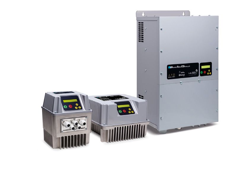
With VASCO - VAriable Speed COntroller inverters
is possible to realise booster sets with one or more
pumps (up to 8) to be controlled at constant pressure.
VASCO - VAriable Speed COn- by the device itself and a metal in case of failure, the remaining
troller can be mounted directly wall bracket. IP 55 protection pumps continue operation to
on the motor fan cover with a does not require including the always guarantee service.
specific kit. The extreme stren- inverter in any additional con-
gth of the connection allows trol box so it can be installed Once the damaged unit is
VASCO - VAriable Speed COn- very near the pump. replaced, COMBO will prefe-
troller installation even on ho- rably move the operation to
rizontal pumps. Screen display COMBO mode control allows the new pumps to equalise
can be easily rotated to opti- to switch the starting of pumps the running time.
mise the parameter view. based on real working time and,
Motor mounting - besides the
compactness and the saving of
additional control panels and
wiring - guarantees very good
cooling of the inverter and low
electromagnetic emissions due
to the reduced length of the
motor cable.
IP55 protection allows installa-
tion in humid and dusty envi-
ronments.
If VASCO - VAriable Speed
COntroller cannot be installed
on the motor fan cover, it is
possible to secure the device
to the wall with an optional kit
composed by a cooling fan fed1 inverter + 1 or 2 DOL pumps
A first method of splitting con-
sists of installing one pump dri-
ven by the inverter and 1 or 2
DOL pumps directly connected
to the main power (Direct On
Line). Inverter switches the 1 or
2 DOL pumps on/off through
contactors. Inverter alternates
the two DOL pumps to avera-
ge pump wear.
From 1 to 8 inverters
in COMBO connection
A second way of splitting (na- Each device controls and pro-
med COMBO) consists of using tects its pump and the opera-
several pumps in parallel (up to tion is shared among all the
8) each driven by an inverter. connected pumps to average
pump wear. In case of failure
In this way, efficiency and the the remaining pumps will main-
reliability of the pump group is tain the pumping operation.
maximised.
From 1 to 8 inverters
+ 1 or 2 DOL pumps
Additionally it is possible to
equip the system with pumps
connected in COMBO mode
plus 1 or 2 DOL pumps to sa-
tisfy additional water demand.VASCO - VAriable Speed COntroller,
in addition to other control modes,
performs the operation at constant
differential pressure
by using a differential pressure
sensor or using 2 pressure sen-
sors installed in the suction and
delivery sides of the pump.
Difference value is calculated
by the inverter itself from the
two values read.
This solution enables significant
cost savings as well as provi-
ding protection against cavi-
tation (by setting a minimum
alarm pressure on the suction
side) and against overpressure
(by setting a maximum pressu-
re alarm on the delivery side).
Constant differential pressu- ∆p
re control can be extended to
e
rv
operation in a group, i.e. twin
cu
pump application.
m
re
essu
ste
ional pr
port
sy
COMBO system ensures al- pro
ternation of the pumps du-
constant pressure
ring operation to average the
pumps’ wear and easily plan
maintenance operations.
In systems characterized by
high drops in pressure, VASCO
- VAriable Speed COntroller 35HZ 40HZ 50HZ
performs the proportional dif-
ferential pressure control to Q
maximise energy saving.Submersible pumps 2 7
Submersible pumps of various powers can be
managed by VASCO - VAriable Speed COntroller. 6
Sometimes it is necessary to install a filter betwe-
en pump and inverter to:
9 8 3 4 5 6
reduce the spikes on the motor coils caused by
voltage reflection (dv/dt filters) 1 Submersible pump
2 Inverter
avoid electromagnetic noise in the surroun- 3 No return valve
4 Pressure gauge
ding environment (sinusoidal filters).
5 Pressure sensor
6 Valve
It is recommended to keep the motor cable se- 7 Pressure tank
parate from other cables, maintaining a certain 8 Output filter
9 Power supply
distance. Nastec can provide filters and shiel-
ded cables for proper pump installation.
1Technical specifications
Model Vin ± 15% Max V out Max I out P2 motor power* Size
VAC VAC A kW
1 x Vin 9 1,1 1
V209 1 x 230
3 x Vin 7 1 ,5 1
1 x Vin 9 1,1 1
V2 1 4 1 x 230
3 x Vin 11 3 1
V218 1 x 230 3 x Vin 18 4 2
V225 1 x 230 3 x Vin 25 5,5 2
V230 1 x 230 3 x Vin 30 7,5 3
V238 1 x 230 3 x Vin 38 9,3 3
V306 3 x 230 3 x Vin 6 1 ,1 1
V309 3 x 230 3 x Vin 9 2,2 1
V3 1 4 3 x 230 3 x Vin 14 3 2
V3 1 8 3 x 230 3 x Vin 18 4 2
V325 3 x 230 3 x Vin 25 5,5 2
V330 3 x 230 3 x Vin 30 7,5 2
V338 3 x 230 3 x Vin 38 9,3 3
V348 3 x 230 3 x Vin 48 11 3
V365 3 x 230 3 x Vin 65 15 3
V375 3 x 230 3 x Vin 75 1 8,5 3
V385 3 x 230 3 x Vin 85 22 3
V3 1 1 8 3 x 230 3 x Vin 118 30 3
V3158 3 x 230 3 x Vin 158 37 4
V3185 3 x 230 3 x Vin 185 45 4
V3215 3 x 230 3 x Vin 215 55 4
V3268 3 x 230 3 x Vin 268 75 4
V406 3 x 380-460 3 x Vin 6 2,2 1
V409 3 x 380-460 3 x Vin 9 4 1
V414 3 x 380-460 3 x Vin 14 5,5 2
V4 1 8 3 x 380-460 3 x Vin 18 7,5 2
V425 3 x 380-460 3 x Vin 25 11 2
V430 3 x 380-460 3 x Vin 30 15 2
V438 3 x 380-460 3 x Vin 38 1 8,5 3
V448 3 x 380-460 3 x Vin 48 22 3
V465 3 x 380-460 3 x Vin 65 30 3
V475 3 x 380-460 3 x Vin 75 37 3
V485 3 x 380-460 3 x Vin 85 45 3
V4 1 1 8 3 x 380-460 3 x Vin 118 55 3
V4158 3 x 380-460 3 x Vin 158 75 4
V4185 3 x 380-460 3 x Vin 185 90 4
V4 215 3 x 380-460 3 x Vin 215 1 10 4
V4268 3 x 380-460 3 x Vin 268 132 4
* Typical motor power. It is recommended to refer to the rated motor current when selecting the suitable model.
Nastec offers a wide range of accessories including pressure sen-
sors, flow sensors, temperature sensors, shielded cables, input
and output filters. For more information, contact our sales staff.General specifications
Rated frequency: 50 - 60 Hz (+/- 2%)
Ambient temperature: - 10 to 40°C (14 to 104 °F)
Max. altitude at rated current: 1000 m
Protection degree:
IP55 (NEMA 4) Sizes 1, 2
IP54 (NEMA 12) Sizes 3, 4
Settable digital outputs, N.O. or N.C. :
1. Motor run signal
2. Alarm signal
3. DOL 1 pump signal
4. DOL 2 pump signal 490 mm
Analog inputs (10 or 15 VDC):
1. 4-20 mA
2. 4-20 mA
3. 4-20 mA or 0 - 10 VDC
4. 4-20 mA or 0 - 10 VDC
4 digital inputs, configurable N.O. or N.C.
for motor run/stop
RS485 MODBUS RTU, Bluetooth® SMART* (4.0)
410 mm
1120 mm
680 mm
260 mm
181 mm
180 mm
228 mm
380 mm
260 mm
260 mm
181 mm
Size 1 Size 2 Size 3 Size 4Nastec reserves the right to modify the technical features contained in this document without notice.
Nastec srl
Via della Tecnica 8
36048 Barbarano Mossano
Vicenza - Italy
tel +39 0444 886289
fax +39 0444 776099
info@nastec.eu
nastec.eu
02.2020
GR000890_rev4You can also read