PM PLUS Controller SPECIFICATION SHEET - Ash Equipment ...
←
→
Page content transcription
If your browser does not render page correctly, please read the page content below
SPECIFICATION SHEET
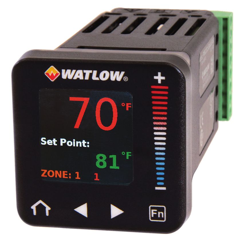
PM PLUS™ Controller
Watlow’s PM PLUS™
Enhances the User
Experience With an
Interface That Enables
Easy Set Up
Watlow’s PM PLUS™, the enhanced EZ-ZONE® PM, is now Bluetooth® compatible with EZ-LINK™ mobile app
more intuitive and features an enhanced interface for easier • Provides full descriptions of parameters and error codes
programming and readability with a SMOOTH-TOUCH™ • Allows remote access capabilities without the use of cables
keypad creating an industry leading user experience. The or converters
PM PLUS is backwards compatible with legacy EZ-ZONE • Provides the ability to configure the product and save
PM controllers but offers many user upgrades including parameter sets
an intuitive menu flow allowing the controller to be easily Integrated PID and limit controller
configured. It also continues to offer the industry leading • Reduces wiring time and termination complexity compared
Bluetooth® connectivity with the EZ-LINK™ mobile app for with connecting discrete products
remote access capability and full descriptions of parameters • Decreases required panel space
and error codes. The PM PLUS improves the user experience • Lowers installation costs
by reducing the complexity at the front of the control while • Increases user and equipment safety for over/under
temperature conditions
eliminating the dependency of cables when configuring the
High amperage power control output
product.
• Drives 15 ampere resistive loads directly
Like the original EZ-ZONE PM, the PM PLUS can be ordered • Reduces component count
as a PID controller, or an integrated controller with multiple • Decreases cost of ownership
functions combined into one. Current monitoring
• Detects heater current flow and provides alarm indication
Now Watlow’s PM PLUS is available through Watlow SELECT®, of a failed output device or heater load
a program that enables you to quickly identify, configure • Drives output on open or shorted heater
and receive your thermal products faster and easier than Serial communication capabilities
ever before. With SELECT, you use a variety of tools to guide • Provides a wide range of protocol choices including
your decision, configure products for an exact fit and quickly Modbus® RTU, EtherNet/IP™, Modbus® TCP, PROFIBUS DP,
receive your order. Visit www.watlow.com/select to learn more. DeviceNet™ and J1939 CAN bus
• Supports network connectivity to a PC or PLC
Features and Benefits Enhanced control options
Intuitive menu flow • Easily handles complex process problems such as ratio,
• Reduces menu structure to a list of lists allowing the differential, square-root, motorized valve control without
controller to be easily configured slidewire feedback, wet-bulb/dry-bulb, compressor control
• Offers easy to read characters and color coding making and peltier loads
the display visible from many angles
SMOOTH TOUCH keypad
• Eliminates contamination points on the front of the
controller
• No mechanical components will wear out
• Creates a better seal on front panel
• Easy to clean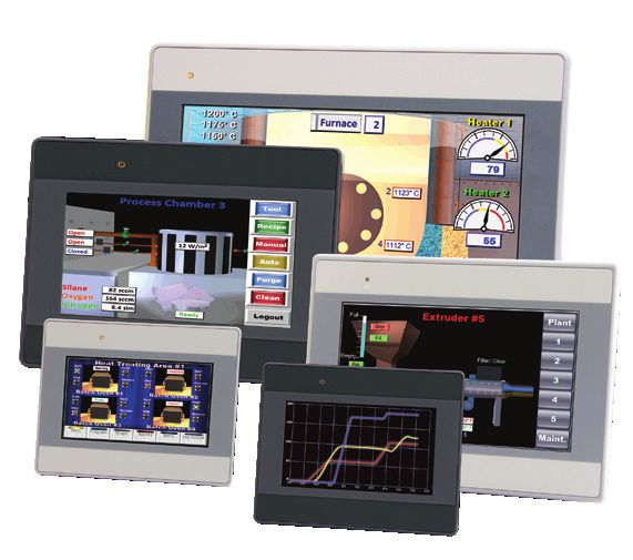
Features and Benefits (con’t)                                Specifications
Countdown timer option                                       Controller
• Provides batch process control                             • User-selectable heat/cool, on-off, P, PI, PD, PID or
• Supports set point change during countdown                   alarm action
10-point linearization curve                                 • Auto-tune with TRU-TUNE+ adaptive control algorithm
• Improves sensor accuracy                                   • Control sampling rates: input = 10Hz, outputs = 10Hz
EZ-LINK™ mobile application for iPhone® and Android™         Profile Ramp/Soak
• Expedites controller setup with intuitive navigation       • 4 profiles, 40 total steps
• Simplifies setting parameters with plain text names
                                                             • Accuracy (typical): ±30 PPM at 77°F (25°C) +30/-100 PPM at
  and descriptions
• Connects quickly and easily via Bluetooth® wireless          -4 to 149°F (-20 to 65°C)
  communications                                             Isolated Serial Communications
Configuration communications with software                   • EIA 232/485, Modbus® RTU
• Includes Watlow standard bus communications used by        • EtherNet/IP™/Modbus® TCP
  COMPOSER® or EZ-ZONE configurator software                 • DeviceNet™
Advanced PID control algorithm                               • PROFIBUS DP
• Offers TRU-TUNE®+ adaptive control to provide tighter      • SAE J1939 CAN bus
  control for demanding applications
                                                             Wiring Termination—Touch-Safe Terminals
• Provides auto-tune for fast, efficient start-up
                                                             • Input, power and controller output terminals are touch safe,
Built-in sensor compensation curves
                                                               removable, 12 to 22 AWG
• Saves cost of buying compensated sensors
• Includes Vaisala RH and altitude (pressure) curves         Universal Input
Remote set point operation                                   • Thermocouple, grounded or ungrounded sensors greater
• Supports convenient set point manipulation from a remote     than 20MΩ input impedance, 3µA open sensor detection,
  device such as a master control or PLC                       2kΩ source resistance max.
Profile capability                                           • RTD 2- or 3-wire, platinum, 100Ω and 1000Ω @ 32°F (0°C)
• Offers pre-programmed process control                        calibration to DIN curve (0.00385 Ω/Ω/°C)
• Allows ramp/soak programming with 40 total steps           • Process, 0-20mA @ 100Ω, or 0-10VDC @ 20kΩ, 0-50mV at
Retransmit output                                              20MΩ, 0-1000Ω potentiometer; scalable; inverse scaling
• Supports industry needs for recording
                                                             Functional Operating Range
Factory Mutual (FM) approved over/under limit with
                                                             Type J: -346 to 2192°F (-210 to 1200°C)
auxiliary outputs
• Increases user and equipment safety for over/under         Type K: -454 to 2500°F (-270 to 1371°C)
  temperature conditions                                     Type T: -454 to 750°F (-270 to 400°C)
Memory for saving and restoring parameter settings           Type E: -454 to 1832°F (-270 to 1000°C)
• Decreases service calls and time down                      Type N: -454 to 2372°F (-270 to 1300°C)
Agency approvals: UL® listed, CSA, CE, RoHS, W.E.E.E., FM,   Type C: 32 to 4200°F (0 to 2315°C)
SEMI F47-0200, Class 1, Div. 2 rating on selected models     Type D: 32 to 4200°F (0 to 2315°C)
• Assures prompt product acceptance                          Type F: 32 to 2449°F (0 to 1343°C)
• Reduces end product documentation costs                    Type R: -58 to 3214°F (-50 to 1767°C)
Touch-safe package                                           Type S: -58 to 3214°F (-50 to 1767°C)
• Increases safety for installer/operator                    Type B: 32 to 3300°F (0 to 1816°C)
• Complies with IP2X requirements                            RTD (DIN): -328 to 1472°F (-200 to 800°C)
Programmable function key                                    Process: -1999 to 9999 units
• Enables simple, one-touch operation of user-defined,
                                                             Accuracy
  repetitive activities
                                                             • Calibration accuracy and sensor conformity: ±0.1% of span,
Programmable menu system
• Reduces setup time and increases operator efficiency         ±1°C @ the calibrated ambient temperature and rated line
Three-year warranty                                            voltage
• Provides product support and reliability                   • Types R, S, B; 0.2%
                                                             • Type T below -50°C; 0.2%
                                                             • Calibration ambient temperature @ 77°F ±5°F (25°C ±3°C)
                                                             • Accuracy span: 1000°F (540°C) min.
                                                             • Temperature stability: ±0.1°F/°F (±0.1°C/°C) rise in ambient
                                                               max.
                                                             Thermistor Input
                                                             • 0 to 40kΩ, 0 to 20kΩ, 0 to 10kΩ, 0 to 5kΩ
                                                             • 2.252kΩ and 10kΩ base at 77°F (25°C)
                                                             • Linearization curves built-in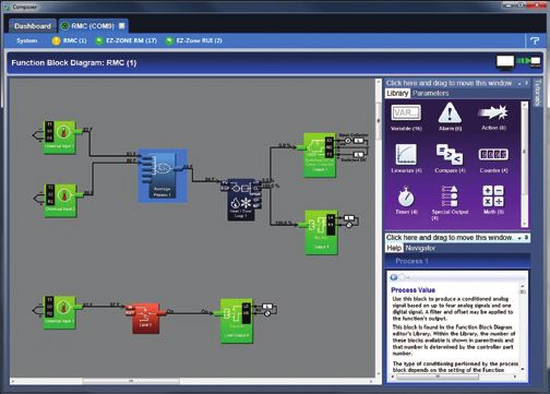
Specifications (con’t)
Current Transformer Input                                          Line Voltage/Power
• Accepts 0-50mA signal (user-programmable range)                  • High voltage option: 85 to 264VAC, 47 to 63Hz
• Displayed operating range and resolution can be scaled and       • Low voltage option: 20 to 28VAC, +10/-15%; 50/60Hz, ±5%
  are user-programmable                                              or 12 to 40VDC
Digital Inputs (DC Voltage)                                        • Max. power consumption: 10VA (1/32 and 1/16 DIN); 14VA
• Max. input: 36V at 3mA                                           Environment
• Logic: min. high state 3V at 0.25mA, max. low state 2V           • Operating temperature: 0 to 149°F (-18 to 65°C)
Digital Inputs (Dry Contact)                                       • Storage temperature: -40 to 185°F (-40 to 85°C)
• Logic: min. open resistance 10kΩ, max. closed                    • Relative humidity: 0 to 90% RH, non-condensing
  resistance 50Ω                                                   Agency Approvals
• Max. short circuit: 20mA                                         • cULus® UL®/EN/CSA C22.2 No 61010-1 Listed, File E185611
2 Digital I/O (ordered with power supply option)                   • CSA C22.2 No. 24, File 158031 (1/32 and 1/16 DIN sizes)
• Update rate: 10Hz                                                • IP 67, IP 66 front seal
• Input type: user-selectable, dc voltage or dry contact           • UL® Type 4X front seal indoor locations
• Output type: switched dc                                         • cULus® ANSI/ISA 12.12.01-2012, CSA-C22.2 No. 213-1987,
• Output voltage: 24V                                                Class 1, Div. 2, Groups A, B, C and D, Temperature Code T4A,
• Output 5: 24mA max. or drive one 3-pole DIN-A-MITE®                File E184390 (optional)
• Output 6: 10mA max.                                              • FM Class 3545 (limit controls)
                                                                   • CE, RoHS by design, W.E.E.E.
Output Hardware
                                                                   • EtherNet/IP™ and DeviceNet™ ODVA Conformance Tested
• Switched dc: 22 to 32VDC @ 30mA max. per single output
                                                                     displays
  and 40mA max. total per paired outputs (1 & 2, 3 & 4)
• Open collector: 30VDC max. @ 100mA max.
• SSR, Form A, 24 to 240VAC, 1A at 50°F (10°C) to 0.5A at 149°F
  (65°C) resistive load, 264VAC max., opto-isolated, without
  contact suppression, 120/240VAC @ 20VA pilot duty
• Electromechanical relay, Form A, 24 to 240VAC or 30VDC
  max., 5A resistive load, 100,000 cycles at rated load, 120/240
  @ 125VA or 24VAC @ 25VA pilot duty
• Electromechanical relay, Form C, 24 to 240VAC or 30VDC
  max., 5A resistive load, 100,000 cycles at rated load, 120/240
  @ 125VA or 24VAC @ 25VA pilot duty
• NO-ARC relay, Form A, 85 to 264VAC, 15A @ 122°F (50°C),
  resistive load, no VDC, 2,000,000 cycles at rated load
• Universal process output: range selectable; 0 to 10VDC
  ±15mV into a min. 1,000Ω load with 2.5mV nominal
  resolution; 0 to 20mA ±30μA into max. 800Ω load with 5μA
  nominal resolution; temperature stability 100ppm/°C
Operator Interface
• LCD display
• SMOOTH TOUCH keypad
• Programmable function key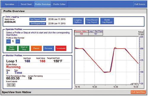
Comparison of Available Features
                                                                                    EZ-ZONE PM6                     PM PLUS
Display Type                                                                        7 segment LED                      LCD
Keypad Interface Type                                                                 Elastomer                   SMOOTH-TOUCH
Express Model Available                                                                   Yes                          None
PID Loops                                                                                  1                             1
Profile Ramp/Soak                                                                    40 total steps                40 total steps
Profile Battery Backup and Real Time Clock                                               None                          None
Number of Digital Inputs/Outputs                                                         0 to 2                        0 to 2
Number of Outputs                                                                        1 to 6                        1 to 6
Integrated Safety Limits                                                                Yes, 1                         Yes, 1
Independent Safety Limit                                                                  Yes                          None
Maximum Power                                                                        15A NO-ARC                    15A NO-ARC
Current Measurement (Accepts 0-50mA Signal From External Current Transformer)             Yes                           Yes
Standard Bus Communications                                                               Yes                           Yes
Bluetooth® Technology                                                                     Yes                           Yes
Field Bus Communications (Modbus® RTU 232/485, EtherNet/IP™, Modbus® TCP,
                                                                                          Yes                           Yes
DeviceNet™, PROFIBUS DP, SAE J1939 CAN bus)
10-Point Calibration Offset                                                               Yes                           Yes
Ratio, Differential and Square-Root                                                       Yes                           Yes
Sensor Compensation Curves-Altitude (Pressure) and Vaisala RH                             Yes                           Yes
       7                                                 5                                                                                             2
Motorized Valve Control (Without6Feedback)                                      4         Yes                 3         Yes
Wet Bulb/Dry Bulb                                                                         Yes                           Yes         REV.                               DESCRIP
                                                                                                                                      1        PROTO
Countdown Timer                                                                           Yes                           Yes           2        Updated

Dimensional Drawing

                    2.10 in.
                  (53.3 mm)                                    0.4 in.
                                                             (10.2 mm)

                                            2.10 in.
                                          (53.3 mm)

                                                                                                  4.164 in.
                                                                                                (105.8 mm)

                                Mounting Panel

                                                                                                                                    UNLESS OTHERWISE SPECIFIED:
                                                                                                                                    DIMENSIONS AND TOLERANCING ARE IN INCHES
                                                                                                                                    AND PER ANSI Y14.5M
                                                                                                                                                                               TH
                                                                                                                                    TOLERANCES:                                 PR
                                                                                                                                    X.X ā 0.015         X.XXX ā 0.005
                                                                                                                                    X.XX ā 0.010        ANGLES ā 2 Ā
                                                                                                                                    MATERIAL
Typical Block Diagram
® EZ-LINK App
250°F
1 2 3
+
4 5 6
7 8 9
- +/-
0 x
Process
Sensor
Integrated
Limit
LOAD
Limit User Power
Sensor Fn Supply
NOTE:
Watlow’s EZ-LINK app is
only available with
Power EZ-ZONE® PM6 and the
Heat Switching Safety PM PLUS controllers.
Source Device ContactorCompatible Accessories
More information is available on these products at
www.watlow.com
Watlow’s new EZ-LINK app allows users to COMPOSER with INTUITION® is
1:04 PM
easily setup, monitor and adjust Watlow Watlow’s easy-to-use software
87oo
CONNECTED DEVICE EZ-ZONE PM and PM PLUS controllers for configuring and customizing
1 PM Controller
via Bluetooth®. The app is available free- controllers. Use it to optimize
Watlow’s F4T and EZ-ZONE PM,
All Parameters
of-charge from the app store for phones
®
180° F 180° F
and tablets, and provides access to the PM PLUS and RM controllers
for specific applications.
Active Process Value Active Set Point
controller’s parameters with fully spelled
out names in plain text with help topics Task-specific views simplify all
that explain each parameter and option. aspects of commissioning new controllers including managing
Home Alerts Device Stored Images More EZ-LINK mobile application connects the inputs and outputs from pluggable flex modules, setting
quickly and easily via Bluetooth® wireless up functions such as control loops and alarms and creating
communications. Download the and editing profiles. COMPOSER software is included on the
EZ-Link App at for Android™ or “Watlow Support Tools” DVD and available for download at
for iPhone®.
EZ-LINK
www.watlow.com.
SpecView is designed for Silver Series EM touch
industrial users with features screen operator interface
such as data logging, trending terminals provide a
and support for bar code customizable user
readers and touch screens. Errors interface, email event
are reduced, for any process, by notifications and log and
creating application-specific graph data for Watlow
screens. The software provides a controllers and other
historical replay option, easy-to-use recipe features and remote devices. A Silver Series EM
access options, including LAN, Internet and modem. operator interface terminal
paired with Watlow
controllers is the perfect solution for your industrial
process or machine control application.PM PLUS PID Model Configuration Code
①② ③ ④ ⑤ ⑥⑦ ⑧ ⑨⑩⑪ ⑫ ⑬⑭
Power Output 1 and
Package Primary Supply 2 Hardware Comm. Future Model Custom
Size Functions Digital I/O Options Options Options Selection Options
PM AAA
③ Package Size ⑧ Communication Options
6 = 1/16 DIN Standard bus always included
④ Primary Functions A = None
C= PID controller with universal input B = Bluetooth® (1/16 DIN models only)*
R= PID controller with universal input and profiling ramp/soak E = EIA 485 Modbus® RTU and Bluetooth® (1/16 DIN models only)*
T= PID controller with universal input and countdown timer 1 = EIA 485 Modbus® RTU
*Note: Bluetooth® not available in all countries, contact factory.
J= PID controller with thermistor input
N= PID controller with thermistor input and profiling ramp/soak ⑨ ⑩⑪ Future Options
S= Custom firmware AAA = Future Options
⑤ Power Supply, Digital Inputs/Outputs (I/O) ⑫ Model Selection
1= 100 to 240VAC P = PM PLUS standard (isolated input 1, input 2 is always isolated)
2= 100 to 240VAC plus 2 digital I/O points X = Not an order option. Appears when Express menu selected.
3= 20 to 28VAC or 12 to 40VDC
⑬⑭ Custom Options
4= 20 to 28VAC or 12 to 40VDC, plus 2 digital I/O points
WP = Watlow PM PLUS face plate
⑥⑦ Output 1 and 2 Hardware Options WN = Watlow PM PLUS face plate no logo/no name
Output 1 Output 2 AG = Conformal coating
CA = Switched dc/open collector None 12 = Class 1, Div. 2 (not available with mechanical relay Output
CH = Switched dc/open collector NO-ARC 15A power control types E, H or J)
CC = Switched dc/open collector Switched dc
CJ = Switched dc/open collector Mechanical relay 5A, Form A
CK = Switched dc/open collector SSR Form A, 0.5A
EA = Mechanical relay 5A, Form C None
EH = Mechanical relay 5A, Form C NO-ARC 15A power control
EC = Mechanical relay 5A, Form C Switched dc
EJ = Mechanical relay 5A, Form C Mechanical relay 5A, Form A
EK = Mechanical relay 5A, Form C SSR Form A, 0.5A
FA = Universal process None
FC = Universal process Switched dc
FJ = Universal process Mechanical relay 5A, Form A
FK = Universal process SSR Form A, 0.5A
AK = None SSR Form A, 0.5A
KH = SSR Form A, 0.5A NO-ARC 15A power control
KK = SSR Form A, 0.5A SSR Form A, 0.5A
Watlow®, Watlow SELECT®, EZ-ZONE®, DIN-A-MITE®, COMPOSER®, TRU-TUNE® and INTUITION®
are registered trademarks of Watlow Electric Manufacturing Company.
PM PLUS™ and EZ-LINK™ are trademarks of Watlow Electric Manufacturing Company.
UL® and CULus® are registered trademarks of Underwriter’s Laboratories, Inc.
Modbus® is a registered trademark of Schneider Automation Incorporated.
Bluetooth® word mark and logos are registered trademarks owned by Bluetooth SIG, Inc.
DeviceNet™ and EtherNet/IP™ are trademarks of Open DeviceNet Vendors Association.
iPhone® is a registered trademark of Apple Corporation.
Android™ is a trademark of Google LLC.PM PLUS Integrated PID Controller Configuration Code
①② ③ ④ ⑤ ⑥⑦ ⑧ ⑨ ⑩⑪ ⑫ ⑬⑭
Power Output 1 and Auxiliary Output 3 and
Package Primary Supply 2 Hardware Comm. Control 4 Hardware Model Custom
Size Functions Digital I/O Options Options Functions Options Selection Options
PM
③ Package Size ⑨ Auxiliary Control Functions
6 = 1/16 DIN A= None
④ Primary Functions R= Auxiliary 2nd input (universal input)
C= PID controller with universal input P= Auxiliary 2nd input (thermistor input)
R= PID controller with universal input and profiling ramp/soak T= Current transformer input (not valid Output 3 and 4)
T= PID controller with universal input and countdown timer selections = FA, FC, FJ and FK)
J= PID controller with thermistor input L = Integrated limit controller with universal input (only valid
Output 3 and 4 selections = CJ, EJ and AJ)
N= PID controller with thermistor input and profiling ramp/soak
M = Integrated limit controller with thermistor input (only valid
S= Custom firmware Output 3 and 4 selections = CJ, EJ and AJ)
⑤ Power Supply, Digital Inputs/Outputs (I/O) Note: If communication options F, G, H, J, K or 2 thru 7 is ordered in
1= 100 to 240VAC previous digit, then Option A must be ordered here.
2= 100 to 240VAC plus 2 digital I/O points All Models: Auxiliary input supports remote set point, backup sensor
3= 20 to 28VAC or 12 to 40VDC ratio, differential and wet-bulb/dry-bulb.
4= 20 to 28VAC or 12 to 40VDC, plus 2 digital I/O points ⑩⑪ Output 3 and 4 Hardware Options
⑥⑦ Output 1 and 2 Hardware Options Output 3 Output 4
Output 1 Output 2 AA = None None
CA = Switched dc/open collector None AJ = None Mechanical relay 5A, Form A
CH = Switched dc/open collector NO-ARC 15A power control AK = None SSR Form A, 0.5A
CC = Switched dc/open collector Switched dc CA = Switched dc/open collector None
CJ = Switched dc/open collector Mechanical relay 5A, Form A CC = Switched dc/open collector Switched dc
CK = Switched dc/open collector SSR Form A, 0.5A CJ = Switched dc/open collector Mechanical relay 5A, Form A
EA = Mechanical relay 5A, Form C None CK = Switched dc/open collector SSR Form A, 0.5A
EH = Mechanical relay 5A, Form C NO-ARC 15A power control EA = Mechanical relay 5A, Form C None
EC = Mechanical relay 5A, Form C Switched dc EC = Mechanical relay 5A, Form C Switched dc
EJ = Mechanical relay 5A, Form C Mechanical relay 5A, Form A EJ = Mechanical relay 5A, Form C Mechanical relay 5A, Form A
EK = Mechanical relay 5A, Form C SSR Form A, 0.5A EK = Mechanical relay 5A, Form C SSR Form A, 0.5A
FA = Universal process None FA = Universal process None
FC = Universal process Switched dc FC = Universal process Switched dc
FJ = Universal process Mechanical relay 5A, Form A FJ = Universal process Mechanical relay 5A, Form A
FK = Universal process SSR Form A, 0.5A FK = Universal process SSR Form A, 0.5A
AK = None SSR Form A, 0.5A KK = SSR Form A, 0.5A SSR Form A, 0.5A
KH = SSR Form A, 0.5A NO-ARC 15A power control Note: If communication options F, G, H, J, K or 2 thru 7 is ordered in
KK = SSR Form A, 0.5A SSR Form A, 0.5A previous digit, then Option AA must be ordered here.
⑧ Communication Options ⑫ Model Selection
Standard bus always included P = PM PLUS standard (isolated input 1, input 2 is always isolated)
A = None V = PM PLUS enhanced firmware which includes compressor control,
B = Bluetooth® (1/16 DIN models only)* ratio, differential, square-root, motorized valve control without
feedback (isolated input 1 and input 2)
E = EIA 485 Modbus® RTU and Bluetooth® (1/16 DIN models only)*
X = Not an order option. Appears when Express menu selected.
F = Modbus® RTU 232/485 and Bluetooth® (1/16 DIN models only)*
G = EtherNet/IP™/ Modbus® TCP and Bluetooth® (1/16 DIN models only)* ⑬⑭ Custom Options
H = DeviceNet™ and Bluetooth® (1/16 DIN models only)* WP = Watlow PM PLUS face plate
J = PROFIBUS DP and Bluetooth® (1/16 DIN models only)* WN = Watlow PM PLUS face plate no logo/no name
K = SAE J1939 CAN bus and Bluetooth® (1/16 DIN models only)* AG = Conformal coating
1 = EIA 485 Modbus® RTU 12 = Class 1, Div. 2 (not available with integrated limit Option “L”
2 = EIA 232/485 Modbus® RTU or “M”, or with Output types E, H or J)
3 = EtherNet/IP™/Modbus® TCP
5 = DeviceNet™
6 = PROFIBUS DP
7 = SAE J1939 CAN bus
*Note: Bluetooth® not available in all countries, contact factory.
Powered by Possibility
To be automatically connected to the nearest International Technical Sales Offices:
North American Technical Sales Office: Austria +43 6244 20129 0 India +91 40 6661 2700 Mexico +52 442 256 2200
China +86 21 3532 8532 Italy +39 02 458 8841 Singapore +65 6773 9488
France +33 1 41 32 79 70 Japan +81 3 3518 6630 Spain +34 91 675 1292
1-800-WATLOW2 • www.watlow.com Germany +49 7253 9400 0 Korea +82 2 2169 2600 Taiwan +886 7 288 5168
UK +44 115 964 0777
©2020 Watlow Electric Manufacturing Company all rights reserved. WIN-PMPLUS-0720You can also read