Power Flow Analysis and Voltage Control using Simulator
←
→
Page content transcription
If your browser does not render page correctly, please read the page content below
Power Flow Analysis and
        Voltage Control using Simulator
       • Formulation of the power flow problem
       • Newton’s method for solving the power flow
       • Description of the PowerWorld Simulator
         Options Dialog accessed from the Options ribbon
         tab, Simulator Options button.
       • Explanation of voltage-related controls
           – generator AVR
           – transformer taps
           – switched shunts

©2008 PowerWorld Corporation                               I7-1
Overall Simulator Solution
                       Methodology
            • Simulator actually uses THREE nested loops
              to solve the power flow
            • MW Control Loop
                 – Voltage Controller Loop                      Voltage
                                                Traditionally   Control
                      • Inner Power Flow loop   called the      Loop also
                                                Power Flow      covered in
                                                Solution
                                                                this section

             MW Control Loop also covered later

©2008 PowerWorld Corporation                                                   I7-2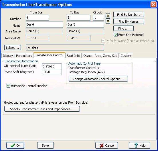
Formulation of Power Flow:
                 “Inner Power Flow Loop”
       • Goal is to solve the nonlinear power balance
         equations for all system buses
       • For an n bus power system
           I = Ybus V
           where
           I = complex vector of current injection at all buses
           V = complex vector of voltage at all buses
           Ybus = complex n by n bus admittance matrix

©2008 PowerWorld Corporation                                      I7-3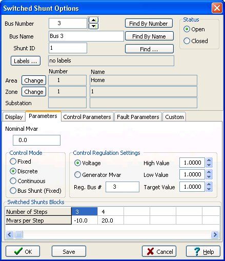
Nonlinear Power Flow Equations

       • Complex nonlinear power balance equations
           S* = V* I
           S* = V* Ybus V
       • Convert to 2(n-1) real equations
           S = g(x) or f(x) = 0
           where
           S = 2(n-1) power injections
           x = 2(n-1) voltage magnitudes and angles

©2008 PowerWorld Corporation                          I7-4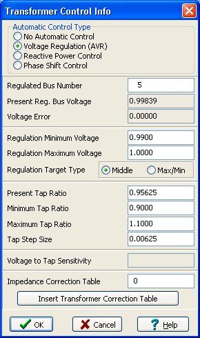
Slack and PV Buses
       • Exactly one bus in each electrical island is
         designated as a slack bus
           –   provides an angle and voltage reference
           –   must be a bus with a generator
           –   voltage angle and magnitude fixed
           –   real/reactive output of generator free to vary
                • Simulator tries maintain them within limits, but if that is not
                  possible, this generator will violate limits
       • At AVR generator buses (PV buses)
           – voltage magnitude is fixed
           – reactive output of generator is free to vary
       • At other buses (PQ buses)
           – Power and Reactive power injections are fixed
©2008 PowerWorld Corporation                                                        I7-5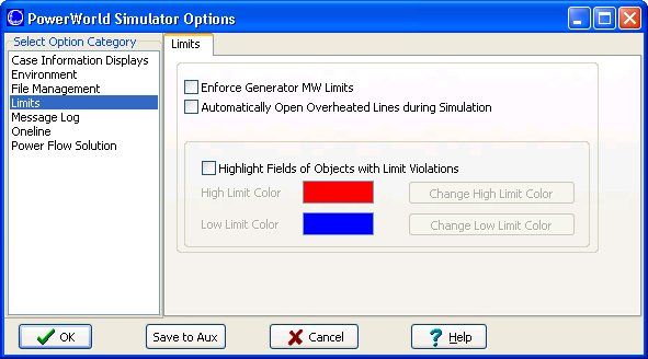
Solving the Power Flow
                        Equations
       • Nonlinear equations must be solved
         iteratively
       • There are a number of common solution
         methods
           – Newton’s Method
                • Simulator uses an enhanced Newton’s method
                  algorithm
           – Fast Decoupled
                • an option in Simulator
           – Gauss-Seidel
                • presently not available in Simulator
©2008 PowerWorld Corporation                                   I7-6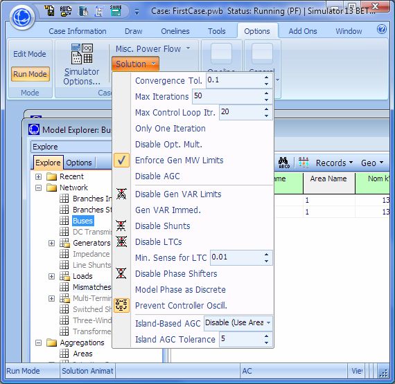
Newton’s Method
       Guess initial value of voltages x0, k = 0
       Repeat
           While ( |f(xk)| > ε ) and (k < kmax) Do
                xk+1 = xk - [J(xk)]-1 f(xk)
                k = k+1
           End While
       Until (no more automatic control changes)

©2008 PowerWorld Corporation                         I7-7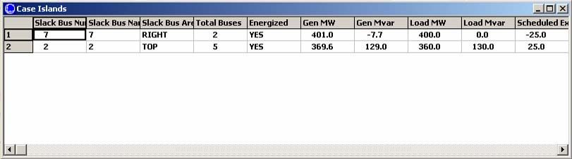
Newton’s Method
       Where
           k              =    Iteration count
           kmax           =    Maximum number of iterations
           xk             =    Voltages at the kth iteration
           f(xk)          =    Mismatch equations
           ε              =    Convergence tolerance (in MVA)
           J(xk)          =    Jacobian matrix

©2008 PowerWorld Corporation                                    I7-8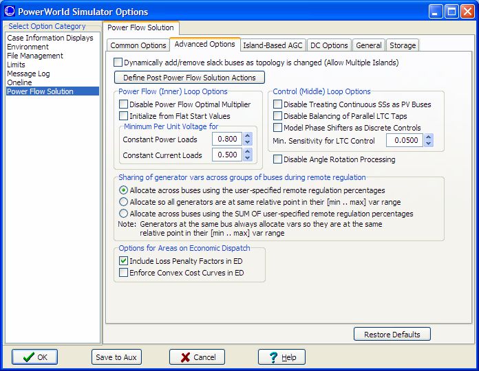
Seven Bus Example
       • Open case B7FLAT.PWB, switch into Run
         Mode and make sure Message Log visible.
       • To view initial mismatches, go to the Case
         Information ribbon tab and select Model
         Explorer. In the Network category select
         Mismatches. All mismatches are initially
         less than 0.1 MVA.
       • Open line from bus 2 to bus 5; refresh the
         mismatches. There are now large values at
         buses 2 and 5. Solve the case.
©2008 PowerWorld Corporation                          I7-9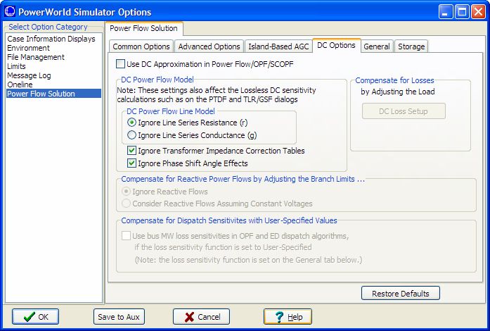
Power Flow Solution
       • Go to the Tools ribbon tab and select Single
         Solution to resolve the power flow
         equations.
       • Refresh the mismatch display; notice that
         mismatches are again less than 0.1 MVA.
       • Notice that voltage magnitude has remained
         fixed at the generator buses. This is
         because they are being modeled as PV
         buses.

©2008 PowerWorld Corporation                            I7-10
Simulator Options:
Power Flow Solution Page
• To customize the power flow solution, go to the
Options ribbon tab and select Simulator Options
ÆPower Flow Solution page
This will open
to the Common
Options tab by
default
©2008 PowerWorld Corporation I7-11Simulator Options:
Power Flow Solution Page
• Common Options Tab
– MVA Convergence Tolerance
• the tolerance for the inner power flow loop
• Must be larger than zero
– Maximum Number of Iterations
• the maximum iterations for the inner power flow loop
– Do only one iteration
• Same as setting Maximum Number of Iterations to 1.
– Disable Automatic Generation Control (AGC)
disables enforcement of MW interchange for entire
case.
©2008 PowerWorld Corporation I7-12Simulator Options:
Power Flow Solution Page
• Common Options Tab
– Unchecking Enforce Generator MW Limits
means generator MW limits are not enforced
– Gen MVAR Limits
• Disable Checking means generator MVAR limits
are not enforced
• Check immediately means the MVAR limits are
checked and handled first before a solution iteration
is run
©2008 PowerWorld Corporation I7-13Simulator Options:
Power Flow Solution Page
• Common Options Tab
– Disable Switched Shunt Control (affects entire case)
– Disable LTC Transformer Control (affects entire
case)
– Disable Phase Shifter Control (affects entire case)
– Transformer Stepping Methodology
• Coordinated Sensitivities looks at all transformers that are
out-of-range and coordinates the movement to bring all
back within regulation range
• Self-Sensitivity Only looks at each transformer
individually and determines the sensitivity of its regulated
value with respect to changing its own tap or phase only
©2008 PowerWorld Corporation I7-14Simulator Options:
Power Flow Solution Page
• Common Options Tab
– Prevent Controller Oscillations
• keeps controlled devices from continually switching
between two control states for the entire case
– Maximum Number of Controller Loop Iterations
• The voltage control loop will be limited to this many
iterations
©2008 PowerWorld Corporation I7-15Simulator Options:
Power Flow Solution Page
• Advanced Options Tab
©2008 PowerWorld Corporation I7-16Simulator Options:
Power Flow Solution Page
• Advanced Options Tab
– Dynamically add/remove slack buses as topology is
changes (Allow Multiple Islands)
• If a single island is split into two islands (by opening lines),
then a new slack bus is chosen (generator with the largest MW
limit is chosen)
– Post Power Flow Solution Actions
• Allow you to define a list of conditional actions (much like a
contingency definition) which occur at the end of EVERY
power flow solution.
• An example would be loads that are automatically taken out of
service when the voltage drops too low.
©2008 PowerWorld Corporation I7-17Simulator Options:
Power Flow Solution Page
• Advanced Options Tab
– Disable Power Flow Optimal Multiplier
• The optimal multiplier is a mathematically calculated step size
for Newton’s Method that prevents the mismatch equations
from increasing between iterations.
– Initialize From Flat Start Values always starts power
flow solutions with voltages at 1.0 per unit and angles
equal to the slack bus angle (not recommended)
– Minimum Per Unit Voltage for Constant Power Loads
and Constant Current Loads
• At voltages less than the defined values, the constant power
and constant current loads will be reduced
• To disable either of these features, set the values to 0
©2008 PowerWorld Corporation I7-18Simulator Options:
Power Flow Solution Page
• Advanced Options Tab
– Disable Treating Continuous SSs as PV Buses
• Continuous switched shunts are normally treated as buses with
fixed power and voltage inside the inner power flow loop.
– Disable Balancing of Parallel LTC taps
• Parallel LTC taps normally have their tap values synchronized
to prevent circulating Var flow.
– Model Phase Shifters as Discrete Controls
• Phase shifters will switch tap positions discretely based on the
tap step size
– Min. Sensitivity for LTC Control
• Transformers with a sensitivity lower than this will be
disabled.
©2008 PowerWorld Corporation I7-19Simulator Options:
Power Flow Solution Page
• Advanced Options Tab
– Disable Angle Rotation Processing
• Voltage angles are rotated so that the angle range in an island is
equally spaced around zero degrees if any angles fall outside +/- 160
degrees
– Sharing of generator vars across groups of buses
• Allocate across buses using the user-specified remote regulation
percentages
• Allocate so all generators are at same relative point in their
[min..max] var range
• Allocate across buses using the SUM OF user-specified remote
regulation percentages
– Options for Areas on Economic Dispatch
• Include Loss Penalty Factors in ED will consider losses in
determining the dispatch
• Enforce Convex Cost Curves in ED will turn units that are operating
outside the convex portion of their cost curve off automatic control
©2008 PowerWorld Corporation I7-20Solution Options Toolbar
• Select the Solution button on the Case Options
ribbon group. Note that most of the settings on the
dialog are available.
Same Setting
©2008 PowerWorld Corporation I7-21Simulator Options:
Power Flow Solution Page
• Island-Based AGC Tab
– Allow load and
generation
balancing
across an island,
instead of Areas
or Super Areas
Options
used for
Injection
Group
Dispatch
©2008 PowerWorld Corporation I7-22Simulator Options:
Power Flow Solution Page
• DC Options Tab
– Use DC Approx. in
Power Flow /
OPF / SCOPF
• Check this box
to model the
system using a
DC power flow.
Note: Once you convert a large
system to a DC power flow, it is
very difficult to get the AC
system to resolve.
©2008 PowerWorld Corporation I7-23Simulator Options:
Power Flow Solution Page
• DC Options Tab
– Compensate for Losses by Adjusting the Load
• Specify a load multiplier at each bus. When solving the
DC power, Simulator will artificially increase loads by
this multiplier
– Compensate for Reactive Power Flows by Adjusting
the Branch Limits
– Compensate for Dispatch Sensitivities with User-
Specified Values
• Allows you to make use of loss sensitivities even in the
DC power flow
©2008 PowerWorld Corporation I7-24Simulator Options:
Power Flow Solution Page
• DC Options Tab
– DC Power Flow Model
• Ignore Line Series Resistance (r)
– b = -1/x, g = 0
• Ignore Line Series Conductance (g)
– b = -x/(r2+x2), g = 0
• Ignore Transformer Impedance Correction Tables
and Ignore Phase Shift Angle Effects (default is to
ignore)
– Impedance correction tends to increase impedance and
phase shift effects tend to decrease impedance
– By not ignoring, DC equations become a function of the
system state and removes some of the advantages of the
DC approximation
©2008 PowerWorld Corporation I7-25Simulator Options:
Power Flow Solution Page
• General Tab
©2008 PowerWorld Corporation I7-26Simulator Options:
Power Flow Solution Page
• General Tab
– Assumed MVA Per Unit Base
• MVA base used for the entire case
• Default is 100 MVA
– Monitor/Enforce Contingent Interface Elements
• Determine when the impact of contingent interface
elements should be calculated
– Bus Loss Sensitivity Function
• Discussed when we go over sensitivities in the
Sensitivity Training section
©2008 PowerWorld Corporation I7-27Simulator Options:
Power Flow Solution Page
• Storage Tab
©2008 PowerWorld Corporation I7-28Islands - Defined
• Often times power system consists of a single
interconnected system operating in synchronism
• However sometimes multiple systems exist that are
either unconnected, or connected only through DC
transmission lines.
• Such systems operate asynchronous with one another
and are called “Islands”.
• Each island must have a slack bus. Check Allow
Multiple Islands.
©2008 PowerWorld Corporation I7-29Multiple Islands in Simulator
• Go to the Options ribbon tab Æ Simulator Options
Æ Power Flow Solution Æ Advanced Options tab
– Check Dynamically add/remove slack buses as topology
is changed
• On the B7FLAT case the slack bus is 7.
• To create two islands, open lines 2-6 and 5-7.
• If new island does not have a slack, Simulator
automatically chooses largest generator
• Repeat with Dynamically add/remove…unchecked
©2008 PowerWorld Corporation I7-30Case with Multiple Islands
Simulator Simulator
has auto- is modeling
matically the two
chosen systems
bus 2 as the as being
slack. completely
independent
Open tie-lines
©2008 PowerWorld Corporation I7-31Island Records Display
It is not uncommon to
Model Explorer ÆAggregations have multiple islands.
Æ Island Records shows Often cases in the
information about each island in Eastern United States
the case, including its slack bus. have Five Islands
©2008 PowerWorld Corporation I7-32Simulator Options:
Message Log Page
• Customize
message log
notation,
contents, and
appearance
©2008 PowerWorld Corporation I7-33Simulator Options:
Environment Page
Can have
“Blackout”
appear if
case does not
converge
Memory limit
for Oneline
Undo feature
©2008 PowerWorld Corporation I7-34Simulator Options:
Oneline Page
Shows hints
when cursor
Display over element
only; no
simulation
Solution
method Non-US
when style XFR
animating symbols
Name of default oneline Name of main oneline file
file to open for ALL cases for CURRENT case
©2008 PowerWorld Corporation I7-35Simulator Options:
File Manage Page
Special options
tab for EPC
and RAW files
Automatically
save over
current PWB.
“0” means do
not Autosave
Enables previously saved PWB files to be automatically
archived each time the file is saved with the same name
©2008 PowerWorld Corporation I7-36Simulator Options:
Case Information Displays
• This was covered in an earlier section on Case
Information Displays
©2008 PowerWorld Corporation I7-37Simulation Options:
Limits Tab
Globally set
enforcement of
generator limits
Can set lines to open
automatically if
overloaded for too
long in simulation
Text fields can be
highlighted if the
value they display
is violating a
defined limit
©2008 PowerWorld Corporation I7-38Generator AVR
• Generator AVR is integrated directly into
the power flow equations. (AVR creates
“PV buses”)
• Generators on AVR maintain a fixed
voltage magnitude at the regulated bus,
provided reactive power output is within
limits.
• To change options, right-click on generator
symbol and select Information Dialog.
©2008 PowerWorld Corporation I7-39Generator Dialog (Edit Mode)
MW Control
will be discussed
later Current reactive
power output
If not checked
then Mvar output
is fixed Check to define
and use MW
Fixed reactive dependent
power limits capability curve
if capability
curve is not
being used
©2008 PowerWorld Corporation I7-40Remote Regulation and Var Sharing
• You may specify a regulated bus number which is
not the terminal bus (commonly called “remote”
regulation)
• Multiple generators may regulate the same bus.
– Generators at different buses will share the total Var
requirement according to the option selected for sharing
vars across groups of buses (Advanced Options Tab of
Power Flow Solution Page)
– Generators at the same bus will coordinate Var outputs
so they are within the same relative location inside their
Var range
– Generators can share at the same bus and remotely
regulate at the same time. In this case the “regulation
percentage”
©2008 PowerWorld Corporation refers to all the generators at the bus I7-41Defining Reactive Capability Curve
• To use a reactive capability curve, on the
Generator Dialog, check Use Capability
Curve.
• Then use table to edit the curve. Right-click
on a column of table (a point on the curve)
to either
– insert a new point (table column)
– delete an existing point (table column)
©2008 PowerWorld Corporation I7-42Reactive Capability Curve
• Enter the following capability curve
• You can view a graph of the reactive
capability curve by selecting Reactive
Capability Curve from the generator menu.
©2008 PowerWorld Corporation I7-43Capability Curve Graph
Current MW
and Mvar
operating point
of the generator
Right-click
on genera-
tor to view
its local-menu
Start the simulation, and then use the spin button to the right
of the generator to change the MW output of the generator.
Notice how the operating point on the graph changes.
©2008 PowerWorld Corporation I7-44Saving Reactive Capability in
Text File
• All power system data, including the
generator reactive capability curve, is saved
in PowerWorld Binary format (*.pwb) files
• Reactive capability curve data is not saved
in most text-based power flow formats, such
as PTI RAW or GE EPC files.
• Simulator provides the ability to save this
data in text files for easy transfer between
cases.
©2008 PowerWorld Corporation I7-45Saving in Text Files
• To save reactive capability data in a text file
– Go to the Model Explorer Æ Network Æ Generators
– Right-Click and choose Save As Æ Auxiliary File
– Choose the filename to save under and Click OK
– You will then be prompted regarding saving the Bid
Curve and Reactive Capability Curve data to the AUX
file. Choose Yes to the Reactive Capability Curve
• Reactive Capability Curves are stored in SUBDATA sections
of the AUX file
– the *.aux file can then be manually edited
©2008 PowerWorld Corporation I7-46Switched Shunt Control
• Switched shunts can automatically change their
shunt susceptance to control voltage at a regulated
bus.
• Switched shunts on continuous control are integrated
directly into the power flow equations. (They create
“PV buses.”)
• Automatic switched shunt control can be disabled in
three places
– for entire case on Simulator Options dialog
– for area on Area Records display
– individually on Switched Shunt dialog
– All three of these flags must be set to enable switched
shunt control in order for a shunt to move.
©2008 PowerWorld Corporation I7-47Switched Shunt Control
• Open Case B5R
• Verify the switched shunt control is enabled
on Power Flow Solution Options dialog
• Verify control enabled on the Area Records
• Right-click on switched shunt shown at bus
3 to display the Switched Shunt dialog.
©2008 PowerWorld Corporation I7-48Switched Shunt Dialog
Status must be closed to work
Actual Mvar will differ if
bus voltage is not 1.0 pu. In discrete mode
high value must
be strictly
greater than
Automatic control low value
requires the mode be
either discrete or When a value goes
See next page out of range,
continuous
Simulator algorithms
Bus Shunt (Fixed) is attempt to set the
the same as Fixed value to the target
(flag used to support
Regulated bus
GE EPC file format)
usually the terminal
bus
Specify the “blocks” of Mvar which are available for shunt
dispatch. This example demonstrated a shunt which has the
ability Corporation
©2008 PowerWorld to provide -30, -20, -10, 0, 20, 40, 60, or 80 Mvars I7-49Switched Shunt Control of
Generator Mvar Outputs
• Switched Shunts may be used to control the Mvar
output of generation
• To do this change the Control Regulation
Settings to Generator Mvar
– Setting Reg. Bus now means to control the total
generator Mvar output for generators which control the
voltage at the bus specified.
JONDAY01 JONDAY03 JONDAY05
150 MW 150 MW 150 MW 150 MW 150 MW 150 MW
39 MVR 39 MVR
39 MVR 39 MVR 39 MVR 39 MVR
0.0 MVR
You could set this shunt to 95% 95% 95%
control the total generator
95% 95%
Mvar output of all 16
generators controlling it’s 150 MW 150 MW
39 MVR 39 MVR
JONDAY07
150 MW 150 MW
39 MVR 39 MVR
JONDAY09 JONDAY11
0 MW
0 MVR
0 MW
0 MVR
0 MW
0 MVR
0 MW
0 MVR
JONDAY13 JONDAY15
0 MW
0 MVR
0 MW
0 MVR
terminal bus
©2008 PowerWorld Corporation I7-50Example Shunt on B5R Case
39 MW
• Bus 3 presently has a -3 MVR 61 MW
-47 MVR
voltage of 0.950 per unit. Bus 3 0.950 pu
• From earlier slide, we set 100 MW
the control range for the 0 MVR
50 MVR
shunt to 0.99 to 1.00 per
40 MW
unit, and switched in the 24 MVR 60 MW
5 MVR
shunt Bus 3 0.994 pu
• This results in the shunt 100 MW
50 MVR
moving to 80 Mvar 79 MVR
nominal 10 MW
22 MVR 40 MW
• If you decrease the load at 14 MVR
Bus 3 1.004 pu
the bus, the voltage starts
50 MW
to increase, so eventually 25 MVR
61 MVR
the shunts reduces
©2008 PowerWorld Corporation I7-51Transformer Tap Control
• Some transformers can automatically change
either their tap ratio or their phase angle to control
either
– voltage - Load Tap Changing (LTC) transformer
– MVAR flow - LTC transformer
– MW flow - phase shifter
• Again, Automatic control can be disabled in three
places
– for entire case on Simulator Options dialog
– for area on Area Records display
– individually on Transmission Line/Transformer
dialog
– All three of these flags must be set to enable switched
shunt control in order for a shunt to move.
©2008 PowerWorld Corporation I7-52Transformer Control
• Verify the transformer control is enabled on
Power Flow Solution Options dialog
• Verify control enabled on the Area Records
• Right-click on transformer shown between
buses 4-5 to display the transformer dialog.
©2008 PowerWorld Corporation I7-53LTC Transformers
Right-click on
transformer Current
symbol to view the off-nominal
Transmission turns ratio
Line/Trans- and phase
former dialog shift
Transformer Must be
LTC options checked to
enable
control
Select to view
LTC Options
©2008 PowerWorld Corporation I7-54Example LTC on B5R Case
• Bus 5 starts with a voltage
Bus 4 0.960 pu
of 0.998 per unit
0.95625 tap
• On previous slide we Bus 5 0.998 pu
showed that tap (on the 100 MW
bus 4 side) was set to 0 MVR
Bus 4 0.923 pu
control voltage at bus 5 0.90625 tap
between 0.99 and 1.00 Bus 5 0.999 pu
• As we increase load tap 200 MW
0 MVR
moves Bus 4 0.975 pu
• As we decrease load tap 0.97500 tap
moves Bus 5 0.999 pu
30 MW
0 MVR
©2008 PowerWorld Corporation I7-55Detailed Overview of PowerWorld
Simulator’s Power flow
Special Pre-processing Techniques
Power Flow Algorithm
Control Switching Hierarchy
MW ControlWhat Does It Mean to do a Single
Solution?
• Single solution should not be confused with a
single Newton-Raphson (or other technique)
power flow
• Simulator’s “Single Solution” encompasses three
nested loops that iterates between a power flow
routine, logic for control device switching, and
generation control until the power flow is solved
and no more device switching is detected
©2008 PowerWorld Corporation I7-57Overview of Single Solution
Routine
• Pre-processing
– Angle Smoothing
– Generator remote regulation viability
– Estimate MW change needed
• Three Nested Loops Solution Process
– MW Control Loop
• Voltage Controller Loop Traditionally Voltage
called the Control Loop
– Inner Power Flow loop also covered in
Power Flow
Solution this section
MW Control Loop also covered later
©2008 PowerWorld Corporation I7-58Pre-processing
• Angle Smoothing
– Reduces large angle differences across
transmission elements that have recently been
closed in to reduce initial power flow
mismatches
– Previously if you closed in a line with a large
angle difference, the power flow would diverge
©2008 PowerWorld Corporation I7-59Pre-processing
• Generator Remote Regulation Viability
– Checks for a viable transmission path between a
generator bus and its remotely regulated bus
– If a generator has no transmission path, or if all possible
transmission routes to the regulated bus are intercepted
by other voltage controlled buses, then the generator is
internally turned off of voltage regulation
OPEN BREAKER
If a generator on left are set to
control voltage at the bus on
the right, then this would
cause convergence difficulty
©2008 PowerWorld Corporation I7-60Pre-processing
• Estimate MW Change
– Stores the initial output of the generators for
referencing during participation factor control
– Modifies generator outputs in each area, super area, or
island (depending on what control is being used) to
meet approximate ACE requirements
– Attempting to prevent slack bus from changing by
drastic amounts during the first Newton-Raphson
power flow calculation in the inner loop
©2008 PowerWorld Corporation I7-61MW Control Loop
• MW Control (Outer Loop)
– Repeat
• Voltage Controller Loop
– Inner Power Flow Loop
• Change generation/load to meet ACE requirements
– Redispatches generation and/or load using the selected
AGC control method for each area (superarea, or island)
– Until no more generation/load changes are
required
©2008 PowerWorld Corporation I7-62Power Flow and Control Loop
• Voltage control switching and Inner Power
Flow Loop
– Repeat
• 1: Inner Power Flow loop
• 2: Generator MVAR Limit Checking
• 3: DC Line Solution
• 4: Switched Shunt Control Switching
• 5: Transformer switching
– Until no more control switching is required
©2008 PowerWorld Corporation I7-63Step 1: Inner Power Flow Loop
• Step 1: Repeat (Inner Power Flow loop)
– Evaluation Mismatch
– Generator MVAR output automatically calculated for PV
buses
– Optionally (enforce Generator
MVAR limits at each step)
– Perform power flow step
» Newton’s Method (this is in rectangular form)
» Decoupled Power Flow
» Polar Form Newton’s Method
• Until no more mismatch
©2008 PowerWorld Corporation I7-64Step 2: Generator MVAR Limits
Step 3: Solve DC line equations
• Step 2: Generator MVAR Limit Check
– Backs off or enforces MVAR limits
– Checks for controller oscillation
» Generators that appear to be oscillating between
control settings are internally set off of control
– Updates mismatch and voltage vectors
» Incorporates voltage vector changes by processing
generators in series
• Step 3: Solve DC line equations
©2008 PowerWorld Corporation I7-65Step 4: Switched Shunt Control
• Step 4: Switched shunt control
– Checks regulated buses for voltage limit violations and adjusts
switched shunt control appropriately
» Also can control the total VAR output for generators
controlling the voltage at a particular bus (good for
modeling a shunt which maintains VAR reserves)
» Shunts are adjusted by one at a time in series with each
shunt only considering it’s impact on the regulated bus’
voltage. The interaction of between different shunts is not
modeled here.
– Checks for controller oscillations
» Switched shunts that appear to be oscillating between
control settings are internally set off of control
– Updates mismatch and voltage vectors
©2008 PowerWorld Corporation I7-66Step 5: Transformer Switching
• Step 5: Transformer switching
– Checks regulated Voltages, MVAR flows, and MW flows for
limit violations and adjusts transformer controls in a manner
dependent on the Transformer Stepping Methodology
» Coordinated Sensitivities: tap change calculation requires
the construction and factorization of a full matrix
dimensioned by the number of transformers which need to
be switched. Normally a small number are changed.
» Self-Sensitivity Only: each transformer does not consider
how it affects other transformers. This calculation is much
faster, but may be less accurate and lead to more iterations
– Checks for controller oscillations
» Transformers that appear to be oscillating between control
settings are internally set off of control
– Updates mismatch and voltage vectors
©2008 PowerWorld Corporation I7-67Complete Process
• Pre-processing
– Angle Smoothing, Remote Viability Check, Area Generator Estimation
• Repeat (MW Control Loop)
– Repeat (Controller Loop)
• 1: Repeat (InnerPower Flow loop)
– Evaluation Mismatch
– Optionally (enforce Generator MVAR
limits at each step)
– Perform power flow step
» Newton’s Method
» Decoupled Power Flow
» Polar Newton
• Until no more mismatch (or max iteration)
• 2: Generator MVAR Limit Checking
• 3: DC Line Solution
• 4: Switched Shunt Control Switching
• 5: Transformer switching
– Until no more control switching is required (or at max iteration)
– Change generation/load to meet ACE requirements
• Redispatches generation/load using the AGC control method for area (island)
• Until no more generation changes are required
©2008 PowerWorld Corporation I7-68You can also read