FIRST Robotics Competition Pneumatics Manual
←
→
Page content transcription
If your browser does not render page correctly, please read the page content below
FIRST Robotics Competition
Pneumatics Manual

The FIRST Robotics Competition (FRC) pneumatic components are outlined in this document. It is being
provided as a courtesy, and therefore does not supersede any information or rules provided in the FIRST
Robotics Competition Manual. For official questions, please go to the FIRST Forums at
http://forums.usfirst.org.

FIRST®, the FIRST® logo, FIRST® Robotics Competition, Coopertition®, Gracious Professionalism®, and
Sport for the Mind™ are trademarks of the United States Foundation for Inspiration and Recognition of
Science and Technology (FIRST®). ©2016-2017 FIRST. All rights reserved.

© FIRST                                FRC Pneumatics Manual                              Page 1 of 23
Contents

Pneumatic Advantages ..................................................................................................................................................3
Pneumatic Components ................................................................................................................................................4
    Pneumatics Control Module .....................................................................................................................................4
    Compressor ...............................................................................................................................................................5
    Pressure Relief Valve .................................................................................................................................................5
    Pressure Switch .........................................................................................................................................................6
    Air Tank .....................................................................................................................................................................6
    Regulators .................................................................................................................................................................7
    Electric Valves ...........................................................................................................................................................7
    Gauges .......................................................................................................................................................................8
    Parker Fittings ...........................................................................................................................................................8
    Tubing........................................................................................................................................................................9
    Custom Bimba Cylinders ...........................................................................................................................................9
Pneumatics Setup ........................................................................................................................................................10
    Compressor and Relief Valve ..................................................................................................................................10
    Pressure Switch, Gauge, and Plug Valve .................................................................................................................11
    Regulator and Gauge ...............................................................................................................................................12
    Actuation .................................................................................................................................................................12
    Electrical Valve ........................................................................................................................................................13
    Air Tank ...................................................................................................................................................................13
    Plumbing .................................................................................................................................................................14
    Wiring ......................................................................................................................................................................14
    Setup .......................................................................................................................................................................15
    Calibration of Relief Valve .......................................................................................................................................15
Resources.....................................................................................................................................................................16
Cylinder Length Example .............................................................................................................................................17
Appendix A...................................................................................................................................................................18
    Example On Board Setups .......................................................................................................................................18
    Example Off Board Setups .......................................................................................................................................19
Appendix B ...................................................................................................................................................................20
Appendix C ...................................................................................................................................................................23

© FIRST                                                             FRC Pneumatics Manual                                                                     Page 2 of 23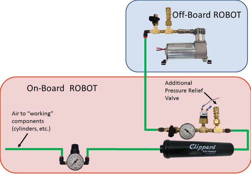
Pneumatic Advantages
Fluid power technology encompasses both hydraulics and pneumatics. Hydraulic applications use
pressurized fluids, mostly oil, while pneumatic applications use pressurized gases, mostly air. Mobile
construction equipment uses a hydraulic pump mounted on the engine. The outlet of the pump is
plumbed to a set of valves. Each valve is then plumbed to a cylinder. This allows you to distribute power
from the engine all around the equipment. The same is true for an FRC robot. Once you install the
compressor operating one valve and cylinder combination, you’ve done most of the work. To add an
additional valve and cylinder combination, you just tee into the pressure line, add in the additional circuit,
and update your code.
Weight - Compare the weight of several valves and cylinders to that of the motors, gears, belts,
and chains used on some lift mechanisms and you will find the weight comparable, if not much
lighter.
Simple to Design - Using pneumatics is much easier than building a motor; gear, chain and
sprocket lift mechanism. Once you have reviewed the layout in Appendix A, you will find it very
easy to build a circuit.
Adjustable Force - To adjust the force of the cylinder, all you have to do is adjust the regulator in
front of it. The force is equal to the area of the cylinder piston times the pressure. Remember that
the valves need a minimum of 15 – 30 psi to work properly.
Durable - All of us have problems burning up motors from time to time. You can stall an air cylinder
against a load indefinitely and turn off the compressor. The materials provided are industrial
grade products.
Strong - Teams have the option of using a small 0.75” bore cylinder at 20psi, a medium cylinder
at 1.5”, or a large 2” cylinder. By varying the pressure to the cylinders, you can produce a force
from 9 pounds up to 180 pounds, depending on your needs.
Custom Cylinders and a Rotary Actuator - You can order the cylinder you need for the job, listed
in Appendix C.
Last Minute Additions - At the last minute, you can add a cylinder and valve very quickly.
© FIRST FRC Pneumatics Manual Page 3 of 23
Pneumatic Components
Below are the components needed to set up an FRC pneumatics system.

                                  Pneumatics Control Module

Cross the Road Electronics’ Pneumatics Control Module (PCM) is in each Rookie Kit. The PCM is used to
control the compressor, solenoids, and pressure switch. The pressure switch should be wired into the 2
Weidmuller ports labeled “PRESSURE SW”, while the compressor’s red and black wires should go directly
into the red and black “COMPRESSOR OUT” Weidmuller connectors.

The PCM can control 8 single solenoid valves or 4 double solenoid valves. It also supports both 12 and 24
volt solenoids however, only one voltage may be used at a time. This 12 or 24 volt selection is done by
relocating the jumper in the “VSOL” slot. The solenoids provide in the Rookie Kit and via FIRST Choice is
24 volt so make sure the jumper is in the correct location before turning on. Finally the PCM receives
power from the PDP via the 2 “Vin” connectors and signal from the 4 “CAN” connectors. The PCM will
handle turning the compressor on and off based on the state of the pressure switch and the Enable state
of the robot. If any Solenoid Valve object is opened (LabVIEW) or constructed (C++/Java) in your code, the
PCM compressor control will be automatically enabled.
© FIRST                                   FRC Pneumatics Manual                               Page 4 of 23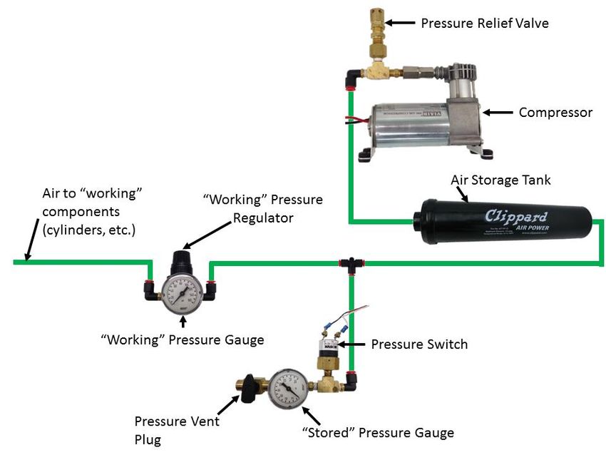
Compressor

Compressors are in each rookie team’s Kickoff Kit and available through FIRST Choice for 2015. The
compressor is a Viair 090C Air Compressor. It will put out approximately 120psi before the relief valve
opens. Because the compressor can produce a significant amount of vibration, we recommend that you
use vibration isolation mounts that come preinstalled on the compressor. In order for these to isolate the
vibration, they need to be mounted to a stiff piece of material, such as a 1/4” aluminum plate. The
compressor can also get very hot and should not be in direct contact with anything else. The compressor
should be wired directly to the “COMPRESSOR OUT” Weidmuller connectors on the pneumatic control
module (PCM). Do not reverse the compressor!

The compressor can be mounted on or off-board the robot. Please read Game & Season Manual Section
8 Robot Rules for all of the rules associated with this.

                                       Pressure Relief Valve

IMI Precision Engineering (formerly known as Norgren) has supplied the 120 PSI pressure relief valve in
each rookie Kickoff Kit as well as FIRST Choice. The pressure relief valve needs to be connected to
compressor via hard fittings. If a team is using an off board compressor, then 2 pressure relief valves will
be necessary, one on the robot and one on the compressor. It is up to the teams to properly install the
relief valve as shown in the instructions below. This is a safety measure meant to ensure proper operation
of the pneumatic system.

© FIRST                                  FRC Pneumatics Manual                                 Page 5 of 23
Pressure Switch

We have included a pressure switch manufactured by Nason in FIRST Choice and the rookie Kickoff Kit for
2015. This switch is normally closed. The switches will open at approximately 115 psi and will not close
again until the pressure drops to approximately 95 psi. This will allow you to turn off the compressor once
you are up to 115psi, saving power in the battery. It must be wired directly to the “PRESSURE SW”
Weidmuller connectors. The PCM will handle turning the compressor on and off based on the state of the
pressure switch and the Enable state of the robot. If any Solenoid Valve object is opened (LabVIEW) or
constructed (C++/Java) in your code, the PCM compressor control will be automatically enabled.

                                                Air Tank

A plastic air tank is available in FIRST Choice and the rookie Kickoff Kit from Clippard Instruments. The tank
is designed to withstand up to 125 psi and temperatures from 35F to 100F. It should also be installed such
that it is protected from impact to reduce the risk of rupturing. When securing the tank ensure that
fasteners do not get over tightened or apply pressure to the tank.

© FIRST                                   FRC Pneumatics Manual                                  Page 6 of 23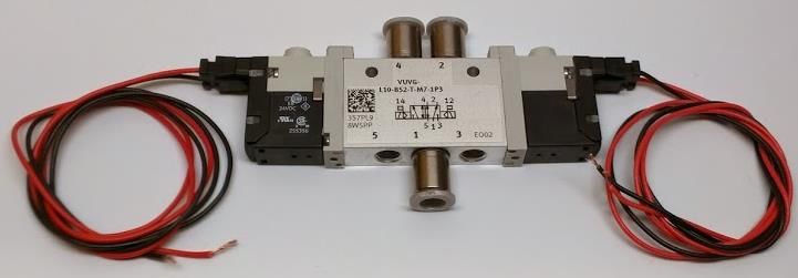
Regulators

IMI Precision Engineering has supplied the primary pressure regulator. This is a relieving regulator. This
means that it will limit the downstream system pressure and can relieve excess pressure if something in
the downstream system causes the pressure to increase. This regulator has a maximum output pressure
of 60 psi and must be placed before any working components. The pressure is adjustable and may be
reduced for use on your robot at your discretion. On the top of the regulator, you will note that one port
extends out a little bit more than the others and has an arrow on it. This arrow is to denote the outlet of
the regulator. The opposite port is the inlet. A pressure gauge may be placed in either of the other ports
if desired, and you will have to plug the other port with one of the enclosed hex plugs.

                                             Electric Valves

FESTO has supplied one complete double solenoid valve kit. The packaging will contain one two way valve,
two plug socket wire, and three fittings. The pictures above are similar to what you will receive in the
rookie kit, except the rookie kit solenoid comes with the electrical base pre-installed. The pneumatic tube
fittings are the “push to connect” type so all you have to do is push in the tubing and then pull back slightly
to ensure a snug fit. The valve is a 24V valve, thus the jumper on the PCM must be in the 24V output
position.

© FIRST                                   FRC Pneumatics Manual                                  Page 7 of 23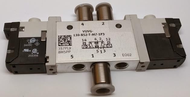
Gauges

IMI Precision Engineering has supplied gauges for 2015. These gauges should be installed in the system to
show stored and working pressure, meaning that two are usually required. The gauges read from 0-160
psi, 0-11 bar, and 0-1.1 MPa. One gauge must be installed on the regulator which will display the working
pressure, which may not exceed 60 psi. The stored pressure gauge can be installed anywhere upstream
of the working pressure regulator.

                                            Parker Fittings

Parker Hannifin donated the plug valve, shown in the bottom left figure above. This valve can be used to
release all of the air in the system. This valve must be installed in a location that will release all system
pressure when opened. The valve should be placed in an easy-to-get-to location on the robot. Parker
Hannifin also donated all the other fittings in the image above as well as the other items in the Rookie Kit
and FIRST Choice. Many of these components are necessary to build a legal pneumatic system and their
usage will be shown in the setup instructions below. It is important to note that all male threads require
Teflon tape to seal properly. To install, wrap the tape around the threads of the fitting. The best method
of wrapping tape is to roll the tape in a direction to match the threads. The recommendation to leave the
first two threads open is to avoid tape coming loose from the first thread that can block one of the valves.

© FIRST                                  FRC Pneumatics Manual                                  Page 8 of 23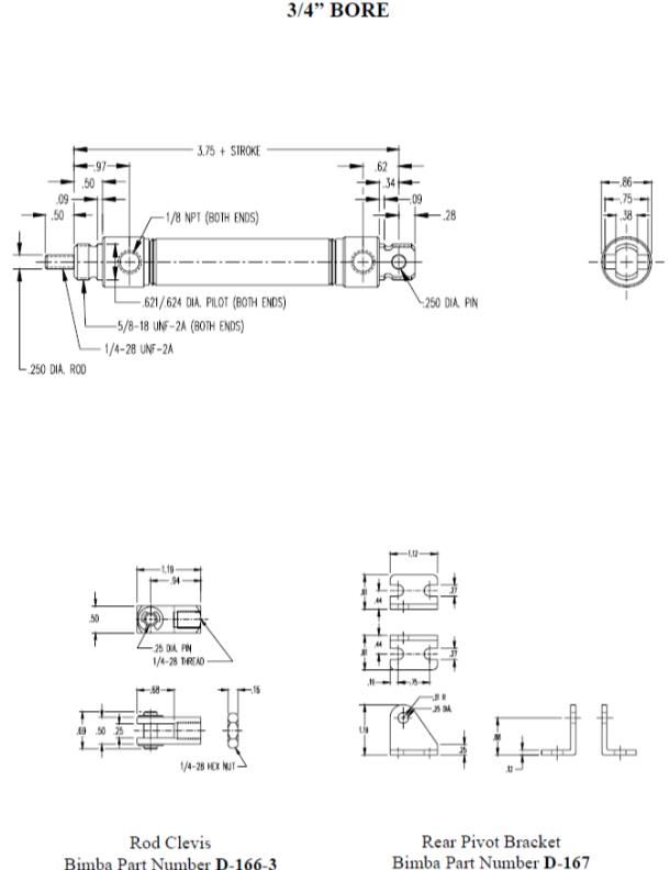
Tubing

Freelin-Wade has donated the pneumatic tubing this year. The tubing has an outside diameter of 0.25”
and an inside diameter of 0.160”. The tubing provided in the rookie Kickoff Kits is black while FIRST Choice
has an assortment of colors. Be careful when cutting tubing as angled cuts can result in leaks.

                                      Custom Bimba Cylinders

You will be able to order custom cylinders for your robot again this year. You have a choice of bore
(diameter) sizes. You can order the stroke (length of extension) you require. This flexibility will significantly
increase your ability to design pneumatics into robot. Most of the bore and stroke options are in stock
and Bimba is ready to ship directly to your team. All the actuators can be ordered with a magnetic piston
and two magnetically operated reed switches. These switches will “close” when the piston is underneath
them. It is not recommended to try to sense a mid-stroke position with these switches. Please follow the
link    posted      in    the    Virtual     Kit    section    of     the    Kit      of     Parts      website
(http://www.firstinspires.org/robotics/frc/kit-of-parts) for custom order information.

© FIRST                                    FRC Pneumatics Manual                                   Page 9 of 23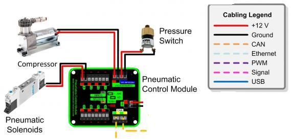
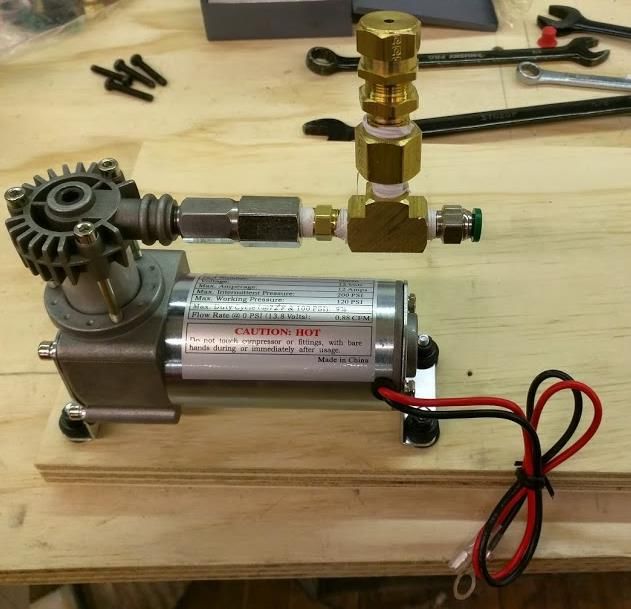
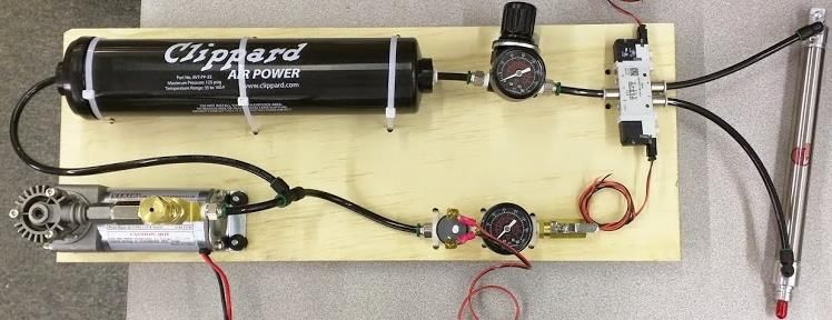
Pneumatics Setup For the purpose of this setup documentation, all components are mounted to a bench top board. Compressor and Relief Valve Steps 1. Install Hex Nipple 1/8” (216P-2) to VIAIR Compressor (00090) output port 2. Connect Union Tee (2203P-2) to Hex Nipple 1/8” (216P-2) 3. Connect Adapter 1/4” to 1/8” F/M (229-4-2) to Union Tee (2203P-2) 4. Install Pressure Relief Valve (16-004-011) to the Adapter 1/4" to 1/8” F/M (229-4-2) 5. Connect Male Connector (W68PLP-4-2) to the final slot on the Union Tee (2203P-2) Notes: Secure all connection points with wrenches Use PTFE tape on all threaded connections The final product should look like the image above The Pressure Relief Valve needs to be calibrated © FIRST FRC Pneumatics Manual Page 10 of 23
Pressure Switch, Gauge, and Plug Valve Steps: 1. Attach Male Connector (W68PLP-4-2) to a slot on the Union Tee (2203P-2) 2. Install Pressure Switch (SM-2B-115R/443) into the middle slot of the Union Tee (2203P-2) 3. Connect Hex Nipple 1/8” (216P-2) to remaining port on Union Tee (2203P-2) 4. Connect a different Union Tee (2203P-2) to Hex Nipple 1/8” (216P-2) 5. Attach Pressure Gauge (18-013-212) to middle port of Union Tee (2203P-2) 6. Connect Hex Nipple 1/8” (216P-2) to remaining port on Union Tee (2203P-2) 7. Attach Micro Valve (MV709-2) to the open threads on the Hex Nipple (216P-2) Notes: Secure all connection points with wrenches Use PTFE tape on all threaded connections The final product should look like the image above © FIRST FRC Pneumatics Manual Page 11 of 23
Regulator and Gauge
Steps:
1. Install one Male Connector (W68PLP-4-2) into the outlet pressure port of the Pressure Regulator
(R07-100RNEA) (designated by a larger port with an arrow pointing away from the regulator)
2. Install another Male Connector (W68PLP-4-2) into the inlet port of the Pressure Regulator (R07-
100RNEA) (this is the opposite port from the outlet where the other male connector was just
installed)
3. Attach Pressure Gauge (18-013-212) to an open port on the Pressure Regulator (R07-100RNEA)
4. Plug the remaining port of the Pressure Regulator (R07-100RNEA with the plugs provided or the
1/8” Plug (218P-2) provide in the KOP
5. The regulator should be mounted using the provided bracket and nut kit
Notes:
Secure all connection points with wrenches
Use PTFE tape on all threaded connections
The final product should look like the third image above
The regulator needs to be adjusted for a specific pressure by rotating the knob
Actuation
Steps:
1. Attach Elbow Push to Connect fittings (W369PLP-4-2) to both the inlet and outlet pressure port
of the actuator
Notes:
Secure all connection points with wrenches
Use PTFE tape on all threaded connections
© FIRST FRC Pneumatics Manual Page 12 of 23Electrical Valve Steps: 1. Screw in all three push to connect fittings into ports 1, 2 and 4 of the Solenoid Valve (566475) 2. Connect both wires (566654) to the Electrical Sub Bases (566716) Notes: The final product should look like the bottom image above but not exactly the same This valve pictured above is a 24 volt solenoid, the same as the one provided in the KOP Air Tank Notes: The air tank in the KOP uses two push to connect fittings to make attachment easier NEVER use the air tank outside of operating conditions Install the air tank on the robot such that it is shielded from impact from other robots When fastening tank do not over tighten or cause pressure to the outside of the tank © FIRST FRC Pneumatics Manual Page 13 of 23
Plumbing
Steps:
1. Cut a piece of Pneumatic Tubing (1A-151-01) and connect it to the Male Fitting (W68PLP-4-2)
directly off the compressor
2. Connect a Push to Connect Union Tee (364PLP-4) to the other end of the Pneumatic Tubing (1A-
151-01)
3. Cut another piece of Pneumatic Tubing (1A-151-01) and connect it between the Union Tee
(364PLP-4) and the Air Tank (AVT-PP-35)
4. Cut a piece of Pneumatic Tubing (1A-151-01) to go between the open slot on the Air Tank (AVT-
PP-35) and the inlet pressure port on the Regulator (R01-100RNEA)
5. Next cut a piece of Pneumatic Tubing (1A-151-01) to go between the outlet pressure port of the
Regulator (R01-100RNEA) and the inlet pressure port (1) of the Electrical Valve
6. Cut two more pieces of Pneumatic Tubing (1A-151-01) to go from the push to connect fittings on
the Electrical valve in ports 2 and 4 to the inlet and outlet ports on the actuator
Notes
Tubing should be cut in a straight line and not at an angle to ensure proper connection
Wiring
Notes
To wire the pneumatic system please refer to the “Wiring Pneumatics” document located here.
© FIRST FRC Pneumatics Manual Page 14 of 23Setup
Notes
To setup the pneumatic system please refer to the “Updating and Configuring Pneumatics
Control Module and Power Distribution Panel” document located here.
Calibration of Relief Valve
Steps
1. Loosen the locknut on the relief valve
2. Jumper the bypass of the Pressure Switch so that the compressor runs continuously
3. When pressure gets to 125psi remove the jumper
4. Rotate cap until air escapes and the pressure remains in the 120-125psi range
5. Finger tighten the locknut
6. Dump air from system then refill with the jumper on the compressor
7. If the system stabilizes somewhere between 120-125psi range further tighten down the locknut,
if it does not adjust the cap again and repeat the process
© FIRST FRC Pneumatics Manual Page 15 of 23Resources
WPI has saved presentations given on many topics by FRC mentors at The FIRST Championship Forums
in the past. Presentations geared towards pneumatics can be found here:
http://first.wpi.edu/FRC/frc-mechanical.html
Appendix C describes the cylinders available to FRC teams as part of the Bimba donation. These items
can be requested online. Please go to www.bimba.com and click on the FIRST link and follow the
instructions. Quantities of no charge custom cylinders will be limited to 2 per team.
© FIRST FRC Pneumatics Manual Page 16 of 23Cylinder Length Example
Look at the drawing of the 1-1/2” bore cylinder in Appendix B. You will notice that the cylinder pivots
about a pivot pin located in the rear of the cylinder. There is a dimension on the drawing from that pin
to the back of the thread on the rod end. That dimension is “4.38 + Stroke”. We will use this later.
Look at the drawing of the rod clevis. There is a locking nut shown on the drawing. If you look, there is a
dimension of the width that is 0.25”. The locking nut threads on the rod first and is used to keep the
clevis in place. Lastly, look at the dimension 1.31” on the rod clevis. Therefore, if you thread the locking
nut on the rod thread all the way to the bottom of the thread and then tighten the clevis against it, you
can calculate the distance from the rear pin to the clevis pin. This is called the pin to pin distance.
Assume you want to move something 8 inches. You will need to order an 8” stroke cylinder.
To find the retracting pin-to-pin dimension, add the following lengths:
Base dimension = 4.38”
Stroke = 8.00”
Locking nut width = 0.25”
Clevis dimension = 1.31”
Pin-to-Pin Retraction = 13.94”
To find the extended pin-to-pin dimension, just add the stroke:
Pin-to-Pin retracted = 13.94”
Stroke = 8.00”
Pin-to-Pin Extended = 21.94”
Note: The retracted length may be somewhat longer by not tightening the clevis all the way to the
end of the thread.
Many thanks to the following FRC Suppliers who provided pneumatic components for the 2015 Kit of
Parts:
Bimba Manufacturing (http://www.bimba.com)
Clippard Instrument Laboratory, Inc. (http://www.clippard.com)
Festo Corporation (http://www.festo.com)
Freelin-Wade (http://www.freelin-wade.com)
HPE Automation (http://www.hpeco.com)
IMI Precision Engineering (formerly Norgren (http://www.norgren.com)
Nason Corporation (http://www.nasonptc.com)
Parker Hannifin, Inc. (http://www.parker.com)
© FIRST FRC Pneumatics Manual Page 17 of 23Appendix A Example On Board Setups © FIRST FRC Pneumatics Manual Page 18 of 23
Example Off Board Setups

© FIRST                    FRC Pneumatics Manual   Page 19 of 23
Appendix B

© FIRST      FRC Pneumatics Manual   Page 20 of 23
Appendix B

© FIRST   FRC Pneumatics Manual   Page 21 of 23
Appendix B

© FIRST   FRC Pneumatics Manual   Page 22 of 23
Appendix C
                    Extend and retract forces
                      of all three bore sizes

                                  3/4" Bore      3/4" Bore
                 Pressure      Force Extended Force Retracted
             (pounds/sq. inch)    (pounds)       (pounds)
                    20                9              8
                    25               11             10
                    30               13             12
                    35               15             14
                    40               18             16
                    45               20             18
                    50               22             20
                    55               24             22
                    60               26             24

                                 1-1/2" Bore    1-1/2" Bore
                Pressure       Force Extended Force Retracted
             pounds/sq. inch      (pounds)       (pounds)
                   20                 35            32
                   25                 44            40
                   30                 53            48
                   35                 62            57
                   40                 71            65
                   45                 79            73
                   50                 88            81
                   55                 97            89
                   60                106            97

                                   2" Bore        2" Bore
                Pressure       Force Extended Force Retracted
             pounds/sq. inch      (pounds)       (pounds)
                   20                 63             57
                   25                 79             71
                   30                 94             85
                   35                110             99
                   40                126            113
                   45                141            128
                   50                157            142
                   55                173            156
                   60                188            170

© FIRST                  FRC Pneumatics Manual                  Page 23 of 23
You can also read