S&C Vista Underground Distribution Switchgear - Outdoor Distribution, 15.5 kV through 38 kV
←
→
Page content transcription
If your browser does not render page correctly, please read the page content below
Featuring
  • Manual,
  • Remote Supervisory, and
  • Source-Transfer Models

           S&C Vista®
Underground Distribution Switchgear
      Outdoor Distribution, 15.5 kV through 38 kV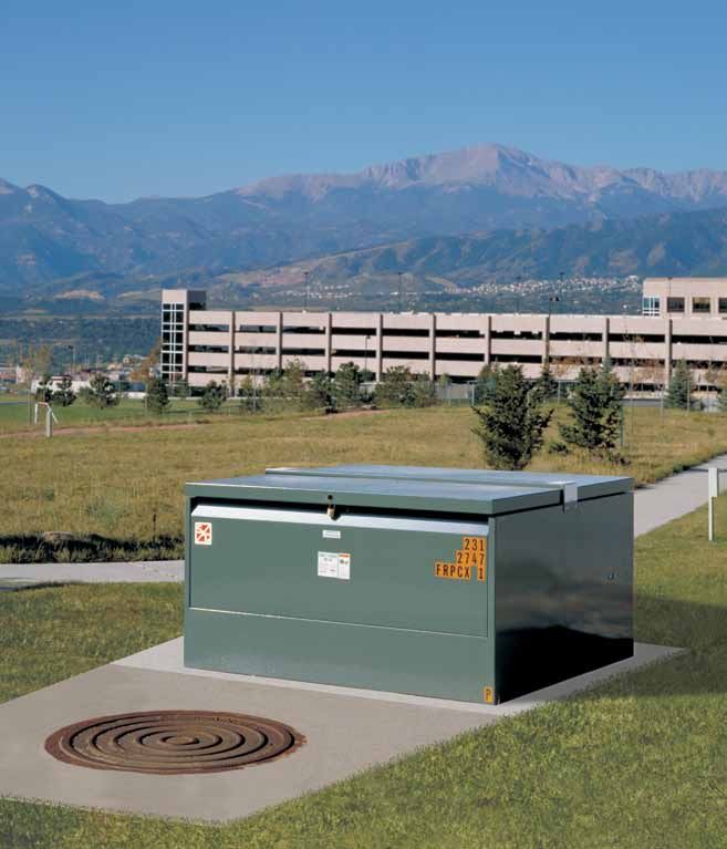
Vista Underground Distribution Switchgear Addresses Your Concerns
• Are you wasting money and resources on time-             underground distribution equipment. Vista UDS is an
  consuming, labor-intensive routine operation of your     exceptional product that meets all of these needs.
  switchgear?                                                 Vista Underground Distribution Switchgear
• Has coordinating upstream protective devices with        is available in manual, remote supervisory, and
  downstream fusing become a headache?                     source-transfer models. All models feature load-
• Are your customers complaining that they don’t           interrupter switches and resettable, vacuum fault
  want obtrusive green boxes on their property?            interrupters or arc spinners in series with disconnect
                                                           switches, elbow-connected and enclosed in a
    S&C’s Vista Underground Distribution Switchgear
                                                           submersible, SF6-insulated, welded steel tank. Vista
is the answer to these and many other underground
                                                           UDS is available with up to six “ways,” in ratings
distribution system problems. S&C worked closely
                                                           through 38 kV and 25 kA symmetrical short-circuit.
with electric utilities and power users to identify and
                                                           Large windows in the tank provide a clear view of the
satisfy needs that were not being met by conventional
                                                           open gap, ground position, and ground bus.

Remote Supervisory Pad-Mounted Style Vista UDS installation.

2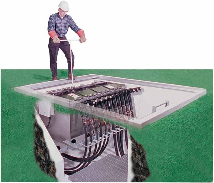
Large viewing windows let you see
open gap and grounded positions
on load-interrupter switches and fault
interrupters. Trip indicators are easily
checked too

Operating panel is                                                  Optional voltage indicator with
located near grade level                                            liquid-crystal display. You can check
so UnderCover™ Style                                                the integrity of the voltage indicator
gear is easily operated                                             by shining a flashlight on the photo-
from a standing position.                                           cell-powered test circuit, while placing
See page 4                                                          a gloved finger over the test button.
                                                                    See page 8. No flashlight needed in
                                           Fault interrupter        daylight
                                           terminals—equipped
                                           with 200-A bushing       Switch terminals—equipped with
Overcurrent control—                       wells, 600-A bushings,   600-A bushings or 900-A bushings
readily programmed                         or 900-A bushings
with your PC
                                                                    Bushings and bushing wells are
                                                                    located on one side of the gear,
                                                                    reducing operating space required
                                                                    for elbows and cables

15-kV UnderCover Style Model 422.

                                                                                                               3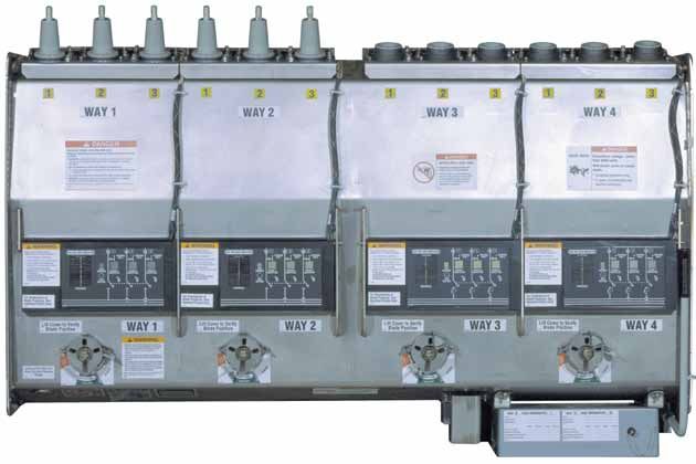
The load-interrupter switches provide three-pole               available with either single-pole or three-pole
live switching of 600-ampere or 900-ampere                        switching. Most models of Vista UDS use in-series
three-phase circuits. The switches have three                     vacuum fault interrupters for fault clearing.
positions (closed-open-grounded) and provide a                    However, the popular 15-kV, 12.5-kA manual models
clearly visible gap when open. The 200-ampere,                    now feature arc-spinning technology for fault
600-ampere, and 900-ampere fault interrupters                     interruption . . . reducing the height of the tank by
offer 40-ms fault clearing, have three-position                   nearly a foot!
(closed-open-grounded) disconnects, and are

                                                                         Compact welded-steel tank protects
                                                                         switching and protection components from
    Optional voltage indicator with liquid-crystal                       the environment. Stainless-steel construction
    display. Includes self-test feature                                  standard in UnderCover Style

                                Operating mechanisms
               Gas-fill port    for switches and fault
                                interrupters—padlockable
                                in any position
 Pressure gauge—(located                                   Operation selector                 Microprocessor-based
 under window) temperature                                 prevents inadvertent               overcurrent control
 and altitude compensated                                  operation from “closed”            housed in watertight
                                                           position directly to               enclosure. CTs (not visible)
                                                           “grounded” position and            provide power and signal
                                                           vice versa                         inputs

Operating panel of Vista UDS gear. Viewing windows, for confirming open gap and grounded position on load-
interrupter switches and fault interrupters, are located under hinged covers of voltage indicators.

4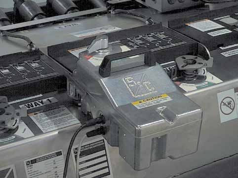
Vista UDS is available in up to six “ways.” This
means it can accommodate any combination of up
to six bus taps, load-interrupter switches, or fault          Conventional
interrupters. With conventional pad-mounted gear,             pad-mounted
for a looped feeder with four taps, two units of gear         gear
are necessary. But with Vista UDS, only one six-way
unit is needed. Vista UDS simplifies installation and
                                                                                 LOAD      LOAD            LOAD       LOAD
improves aesthetics by reducing the necessary                                      1         2               3          4
real estate.
                                                              Vista
   The model number indicates the total number of             Underground
ways, as well as the number of load-interrupter and           Distribution
fault-interrupter ways. For example, Model 321 has            Switchgear
“3” ways—“2” load-interrupter switch ways and “1”
fault-interrupter way, as shown below.
                                                                                         LOAD    LOAD   LOAD   LOAD
                                                                                           1       2      3      4

 TYPICAL CONFIGURATIONS OF MANUAL AND REMOTE SUPERVISORY VISTA UDS

                     201                                321                                   422

                            514                                                         624

 TYPICAL CONFIGURATIONS OF SOURCE-TRANSFER VISTA UDS

           V                       V                                 V                                                V
           T                       T                                 T                                                T

                      321                                                                       523

                                       V                                     V
                                       T                                     T

                                                  532 (split-bus)

                                                                                                                             5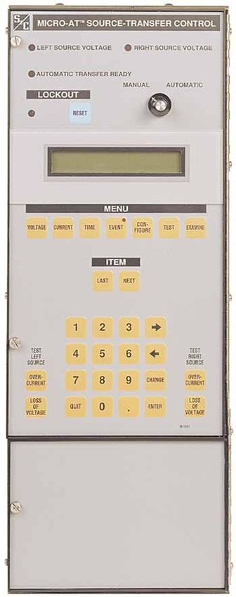
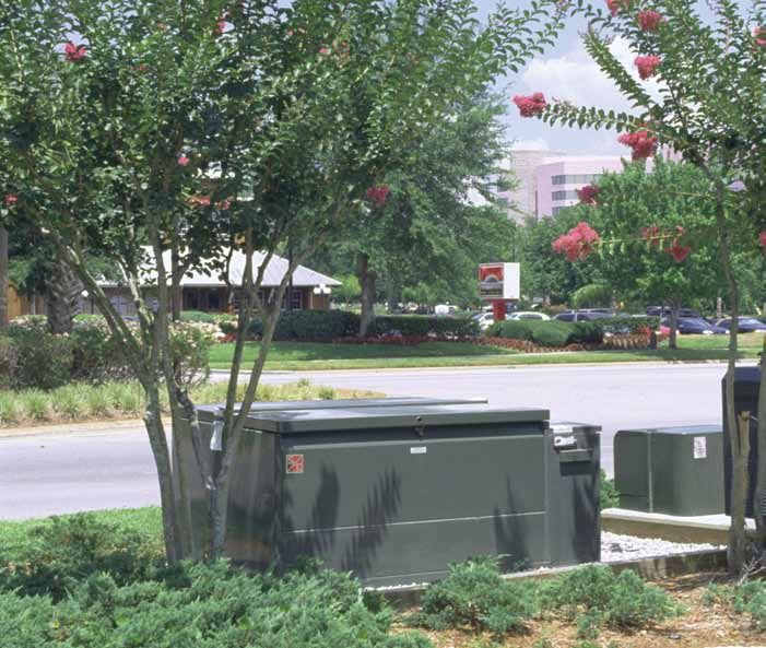
Vista UDS Offers Numerous Unobtrusive                     for areas with stringent real-estate restrictions or
Installation Options                                      where aesthetics are extremely important. The Vista
                                                          UDS gear is installed underground, but all operations
One option is the low-profile pad-mounted style. At
                                                          are easily performed by one operator above ground.
15, 25, and even 34.5 kV, pad-mounted Vista UDS is 6
                                                          UnderCover style installations can also save money
to 14 inches shorter than the average SF6-insulated
                                                          by reducing costs associated with trenching and long
gear. And Vista UDS’s total real-estate requirement
                                                          cable runs.
is less than one-third that of a typical SF6-insulated
design. This means that Vista UDS is easier to site and      Vista UDS is also available for floor-mounted or
allows more room for landscaping options that further     wall-mounted vault installations, and in a man-hole
improve aesthetics.                                       style. With its compact design, rugged construction,
                                                          and internal visible open point, man-hole style Vista
   Vista UDS’s most innovative installation offering is
                                                          UDS is perfect for applications where installation
the UnderCover style. The UnderCover style is ideal
                                                          space is limited.

UnderCover Style.                                               Pad-Mounted Style.

Vault-Mounted Style—available for floor and                     Man-Hole Style.
wall-mounting.

6
Vista UDS Operation Is Quicker,                             1. Rotate the switch operating shaft to the “open”
Easier, Safer                                                  position, then confirm the open gap through the
                                                               large viewing window. See Figures 1 and 2. With
Vista UDS was specifically designed to simplify
                                                               ordinary elbow gear, on the other hand, specially
operating tasks, enhance safety, and minimize
                                                               trained operators need to remove the elbows from
the duration of outages. Vista UDS is certified
                                                               their bushings using a shotgun clamp stick—a
arc-resistant per IEC 298 Appendix AA, for currents
                                                               tedious task that must be carefully performed. See
up to 12.5 kA symmetrical for 15 cycles (25 kA
                                                               Figure 3.
symmetrical for 15 cycles, for models rated 25 kA
short-circuit). In the event of an internal fault, the
enclosure will retain its integrity.
  Just one person is needed to operate Vista
UDS. There’s no exposure to medium voltage. The
procedure is simple:

 “Grounded”                  Switch blade in
 position                    “open” position
 contact
                                               “Closed”     Figure 1. Opening load-interrupter switch (or fault
                                               position     interrupter).
                                               contact

                            Vacuum bottle

Fault interrupter furnished on all Vista UDS except 15-kV
manual models.
                                                            Figure 2. Window cover lifts for viewing switch-blade
   Arc-spinning                           Switch blade      positions of load-interrupter switch or fault interrupter.
                   “Closed” position      in “open”
   contact
                   contact                position
                                          “Grounded”
                                          position
                                          contact

Fault interrupter furnished on 15-kV, 12.5-kA manual        Figure 3. Operation of typical dead-front gear can be
models.                                                     awkward and time-consuming.

                                                                                                                    7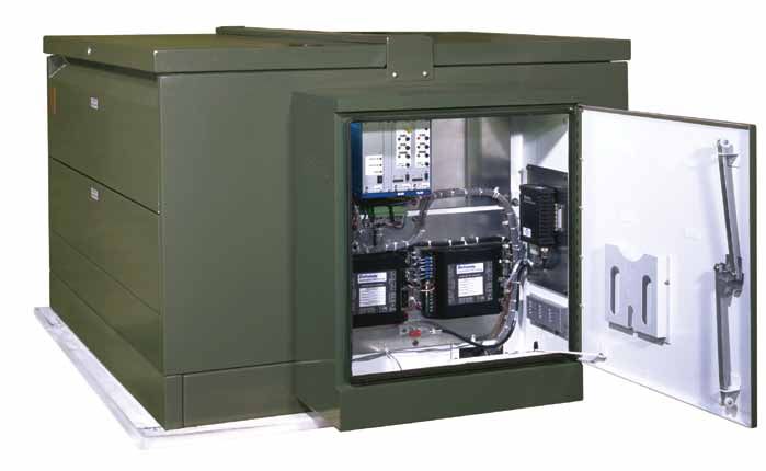
2. Confirm that the cable is de-energized so it can be
   safely grounded. With traditional gear, the medium-                           Test circuitry can be powered by
                                                                                 flashlight or bright sun
   voltage cables must be tested directly using a
   clampstick-mounted tester. But voltage testing with                                 Place gloved finger over
   Vista UDS can be accomplished simply and easily                                     test button to begin testing
   without ever accessing the cables. Simply use the
   voltage indicators shown in Figure 4. The voltage
   indicator is even equipped with a self-test function,
   so you can “test the tester.”  See Figure 5.
3. Ground the cables. Instead of the awkward task of
   having to move the elbows to parking stands, along
   with the grounding bushings or elbows, with Vista
   UDS you need only rotate the switch operating shaft
   to the “grounded” position. See Figure 6. Grounding     Figure 5. Testing the voltage indicator.
   can easily be confirmed by looking through the
   viewing window.
   There are even more benefits: The voltage indicator
can be furnished with a low-voltage phasing option.
See Figure 7. This feature allows confirmation of
proper phasing without ever accessing the cables.
Vista UDS allows fault-locating and hi-potting tests
to be performed with the cables attached—and the
bus energized.

                              Test button
    Photocell for
    energizing self-   Test window          LCD display
    test feature
                                                           Figure 6. Grounding load-interrupter switch (or fault
                                                           interrupter).

Figure 4. Voltage indicator.

                                                           Figure 7. Measuring phase-to-phase voltage—Phase
                                                           1 to Phase 1.

8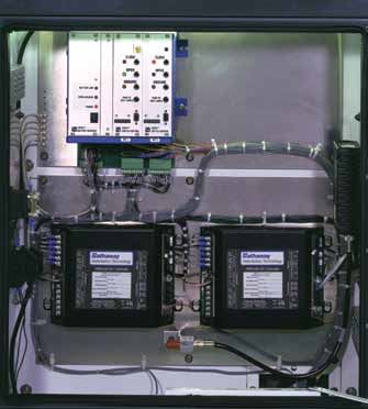
Overcurrent Control                                                                   1000

for Superior Coordination                                                                    Transformer-
                                                                                                                                   Vista Tap
                                                                                                                                   Interrupter (Phase)
                                                                                             Primary Fuse                           Min. Pickup Current: 400A
Vista UDS utilizes a unique microprocessor-based                                             (100E, Standard
                                                                                             Speed)
                                                                                                                                    Def. Time Delay: 4 cycle

overcurrent control, housed in a watertight enclosure                                  100

mounted on the gear. The overcurrent control                                                                                         Phase
                                                                                                                                     Overcurrent Relay
features a variety of TCC (time-current characteristic)                                                                               Type: CO-9
                                                                                                                                      Time Dial: 3

                                                                    TIME IN SECONDS
curves with selectable instantaneous and definite-                                      10                                            Min. Pickup Current:
                                                                                                                                      720A

time delay attributes, for superior coordination with
                                                                                                                                      CTI: 0.15 sec.

upstream protective devices and downstream fusing.
The parameters for the TCC curves are set using a                                        1

personal computer connected to the data port of the
overcurrent control. There are no knobs or dials,
so the settings cannot be inadvertently changed or                                      .1

altered by unauthorized personnel. Integral current
transformers provide power and current sensing.                                        .01
There is even an event recorder that captures

                                                                                                                           1,000
                                                                                             10

                                                                                                                                                                100,000
                                                                                                               100

                                                                                                                                               10,000
information on the last twelve operations of each                                                               CURRENT IN AMPERES
fault interrupter.
                                                                 Coordinating-speed tap curve with definite-time
                                                                 delay eliminates miscoordination problems
                                                                 frequently encountered with transformer fuses.

User-supplied personal computer is attached to the overcurrent control for programming the relay in the field.

                                                                                                                                                                          9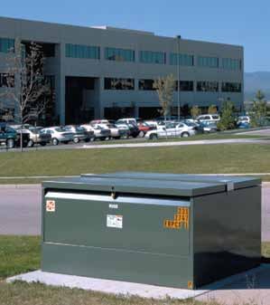
Remote Supervisory Vista UDS
                                                                    Position indicator   Padlock feature
For distribution automation applications, S&C offers
Remote Supervisory Vista UDS. Remote Supervisory                     Operator
Vista UDS provides automated switching and fault                     selector
protection, and can also perform auto-sectionalizing
without tripping the main breaker. Automation
features are also retrofittable to existing Manual Vista
UDS. Motor operators, current and voltage sensors,
and low-voltage compartment are easily installed in
the field.
   Each motor operator includes a control board that
provides local push-button and remote operation
between the “closed,” “open,” and “grounded”
positions. Up to six control boards can be
accommodated within the low-voltage compartment,
so any or all load-interrupter switches or fault
interrupters can be motor operated. The motor
                                                           Details of motor operator.

15-kV Remote Supervisory Pad-Mounted Style Model 422.

10
operators may be battery powered or, optionally,
self-powered using internal voltage transformers.
The low-voltage compartment may also contain
a user-specified remote terminal unit and
communication device, providing a completely
automated switching and protection package.
Optional voltage and current sensing round out the
Remote Supervisory Vista UDS offering.
A variety of RTUs have been successfully
integrated in Remote Supervisory Vista UDS,
including: ACS, Harris DART, Valmet PoleCAT,
QEI/Quindar, Hathaway/Systems Northwest,
Motorola MOSCAD, and DAQ.
And these transceivers have been integrated:
Metricom Utilinet, MDS, Dymec, H&L, and Motorola.
RTUs and communication devices of other
manufacture can be accommodated too; contact your
nearest S&C Sales Office.
Details of low-voltage compartment of Remote
Supervisory Vista UDS Model 422.
Position-indicating
lamps
Operation
push buttons
Push-to-test lamps
Connector for portable
motor operator control
Operation counter
Vista motor controls for installation with two motor-operated ways.
11When Remote Supervisory Vista UDS is furnished a SCADA master station. And, when Remote
with an EnergyLine 5800 Series Switch Control, it can Supervisory Vista UDS is fitted with an EnergyLine
be a member of an IntelliTEAM®, using EnergyLine’s switch control, the gear can be used for automatic
revolutionary peer-to-peer communications. source transfer, with remote control and monitoring.
IntelliTEAM software supports automatic Remote Supervisory Vista UDS also allows the user
sectionalizing and reconfiguration, significantly to remotely trip the vacuum bottles of any three-phase
reducing outage time. IntelliTEAM’s peer-to-peer fault interrupter way using external, user-specified
communication network uses distributed intelligence, relays. This additional shunt-trip capability permits
eliminating the need for, but still fully supporting, advanced applications like sensitive earth-ground fault
detection, as well as protective relay schemes using
high-speed communication for closed-loop and open-
loop systems.
Portable Motor Operator
Local motor operation of Vista UDS gear is also
available for users who do not require a complete
automation package. The portable motor operator
includes cabling and hand-held control, all in an easily
portable, durable case.
The operator easily attaches to any load-interrupter
switch or single-pole or three-pole fault interrupter.
Then simply plug in the power cable and the control
cable. The hand-held control features “open,” “close,”
and “ground” push buttons, an “enable” button
to prevent inadvertent operation, and a “ready”
Remote Supervisory Vista UDS with 5800 Series
indicating light.
Switch Control.
Vista UDS Portable Motor Operator. Inset shows hand-held control.
12Case for Vista UDS Portable Operator.
Source-Transfer Vista UDS
Source-Transfer Vista UDS provides fully automatic
primary-selective service for one, two, or three
critical load circuits. This package includes all
the features of Manual Vista UDS, plus the S&C
Micro-AT® Source-Transfer Control, three-phase
voltage sensing on source ways, and internal power
provided by voltage transformers. It is available in
common-bus and split-bus configurations.
The Micro-AT Source-Transfer Control, located in
the low-voltage compartment, ensures a high degree
of critical-load continuity by minimizing interruptions
resulting from the loss of one source. Excluding the
intentional time delay to coordinate with upstream
protective devices and/or transition dwell time,
transfer is achieved in 6 seconds maximum.
The Micro-AT Source-Transfer Control utilizes
an advanced microprocessor to perform control
operations, as directed by settings programmed
into the device at the factory and in the field.
Such settings, consisting of the control’s operating
characteristics and voltage-, current-, and time-related
operating parameters, are entered into the control by
means of a keypad on the front panel.
An unbalance detection feature may be
field-programmed in the Micro-AT Source-Transfer
Control. This feature protects the loads from any
source-side open-phase condition at the same voltage
as the Vista Underground Distribution Switchgear.
If the voltage unbalance exceeds a preset reference
level for a period of time sufficient to confirm that
the loss is not transient, an output signal is produced
which initiates automatic transfer to the other source.
An overcurrent-lockout feature may be furnished
which prevents an automatic transfer operation that
would close a source load-interrupter switch into a Micro-AT Source-Transfer Control.
fault. A light-emitting diode lamp indicates when
lockout has occurred. Test keys are provided for
simulating an overcurrent condition on each source.
13Standard Three-Phase Ratings123
Amperes, RMS
Fault Interrupter Load-Interrupter Switch
Continuous, Continuous,
Load Load
Applicable Short- Main Bus
Frequency, Dropping, and Fault Dropping, and
Standard Fault- Fault- Momen- Circuit, Continuous
Hertz Load Splitting Inter- Load Splitting 1 Sec.,
(Parallel or Closing, (Parallel or Closing, tary, Sym. Current7
rupting, Sym.
Loop Sym. Loop Sym. Sym.
Sym.
Switching) Switching)
456 456
200 or 630 12 500 12 500 200 or 630 12 500 12 500 12 500 12 500 600
IEC 50 or 60
630 25 500 25 000 630 25 500 25 000 25 000 25 000 600
200 or 630 12 500 12 500 200 or 630 12 500 12 500 12 500 12 500 600
ANSI 50 or 60
600 25 500 25 000 600 25 500 25 000 25 000 25 000 600
1 Refer to the nearest S&C Sales Office for other ratings. 5 Fault interrupters and load-interrupter switches can switch the magne-
2 IEC ratings have been assigned in accordance with the applicable tizing current of transformers associated with the load-dropping rating. In
addition, unloaded cable switching ratings are as follows: 10 amperes at
portions of IEC 265-1 for a Class A switch.
15.5 kV and 20 amperes at 29 kV and 38 kV.
3 ANSI ratings have been assigned in accordance with the applicable
6 900 ampere is also available.
portions of ANSI C37.71, C37.72, and C37.73.
4 Fault interrupters and load-interrupter switches are rated 600 amperes 7 1200 ampere is also available.
(630 amperes IEC) continuous, load dropping, and loop splitting when fur- 32,500-ampere peak ten-time duty-cycle rating.
nished with 600-ampere bushings (standard for load-interrupter switches 65,000-ampere peak three-time duty-cycle rating. Ten-time duty-cycle
and 25-kA fault interrupters, optional for 12.5-kA fault interrupters). The
fault-clearing rating is 16,000 amperes symmetrical, 41,600 amperes
rating is limited to 200 amperes if 200-ampere bushing wells are used
peak.
(standard for 12.5-kA fault interrupters, optional for 12.5-kA load-inter-
rupter switches). Models rated 25-kA are only available with 600-ampere
bushings.
14Printed in U.S.A. Descriptive Bulletin 680-30 June 1, 20 04© Offices Worldwide f www.sandc.com
You can also read