EMGZ492.ECAT Operating Instructions - FMS
←
→
Page content transcription
If your browser does not render page correctly, please read the page content below
Operating Instructions
EMGZ492.ECAT
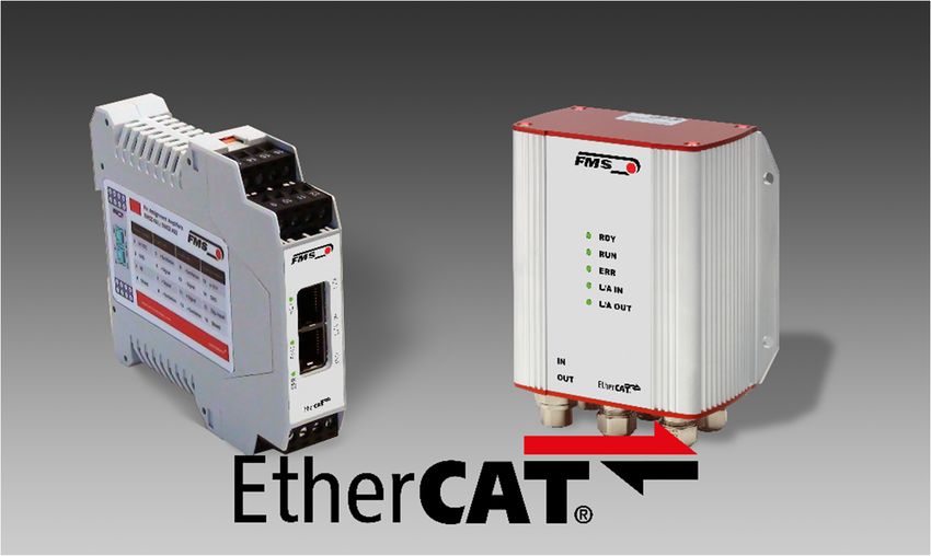
Dual channel measuring amplifier for EtherCAT®
EMGZ492.R.ECAT for mounting on DIN rail
EMGZ492.W.ECAT for wall mounting
Dokument Version 1.4, 01/2021 NS
Firmware Version V 2.0.4
ESI Datei FMS_TensionAmplifier_EMGZ49X.xml
Diese Bedienungsanleitung ist auch in Deutsch erhältlich.
Bitte kontaktieren Sie Ihre lokale FMS Vertretung.
EtherCAT® is a registered trademark and patented technology, licensed by Beckhoff
Automation
© by FMS Force Measuring Systems AG, CH-8154 Oberglatt – All rights reserved.
GmbH, Germany.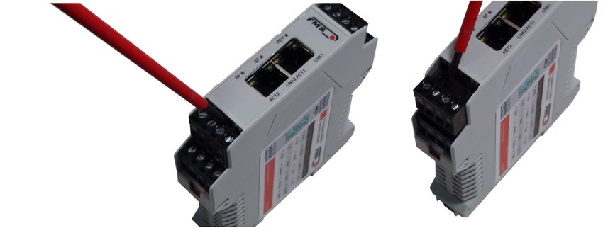
Operating Instruction EMGZ492.ECAT

1 Table of Contents

1        TABLE OF CONTENTS ............................................................................................................................. 2
2        SAFETY INFORMATION ........................................................................................................................... 3
     2.1     Presentation of Safety Information ..................................................................................................... 3
        2.1.1 Danger that Could Result in Minor or Moderate Injuries ............................................................... 3
        2.1.2 Note Regarding Proper Function ................................................................................................... 3
     2.2     General Safety Information ................................................................................................................ 4
3        PRODUCT DESCRIPTION ........................................................................................................................ 5
     3.1         Block Diagram .................................................................................................................................... 5
     3.2         System Description ............................................................................................................................ 5
     3.3         Scope of Delivery ............................................................................................................................... 5
4        QUICK GUIDE/QUICK START .................................................................................................................. 6
     4.1     Preparations for Parameterization ..................................................................................................... 6
     4.2     Mounting Sequence ........................................................................................................................... 6
     4.3     Mounting and Electrical Connections................................................................................................. 6
     4.4     Load Cell Mounting ............................................................................................................................ 7
     4.5     Electrical Connections........................................................................................................................ 7
        4.5.1 EMGZ492.R.ECAT ........................................................................................................................ 7
        4.5.2 EMGZ492.W.ECAT ....................................................................................................................... 8
        4.5.3 Ethernet Connections .................................................................................................................... 9
5        CALIBRATION OF THE MEASURING SYSTEM .................................................................................... 10
     5.1     Offset Compensation ....................................................................................................................... 10
     5.2     Calibration in the Amplifier (Adjusting the Gain Factor) ................................................................... 10
     5.3     Calibrating ........................................................................................................................................ 11
     5.4     Gain .................................................................................................................................................. 11
     5.5     Limit Value Violations ....................................................................................................................... 12
        5.5.1 Overload Test .............................................................................................................................. 12
        5.5.2 Overflow and Underflow Test ...................................................................................................... 13
     5.6     Description of the LEDs ................................................................................................................... 13
6        INTEGRATION INTO THE ETHERCAT® NETWORK ............................................................................. 14
     6.1         EtherCAT® Interface ......................................................................................................................... 14
     6.2         System Start ..................................................................................................................................... 14
     6.3         Data Exchange ................................................................................................................................. 14
7        CONFIGURATION.................................................................................................................................... 15
     7.1         Parameter Description ..................................................................................................................... 15
     7.2         Cyclic Data Traffic ............................................................................................................................ 18
     7.3         Acyclic Data Traffic .......................................................................................................................... 21
8        ETHERCAT® COMMUNICATION ............................................................................................................ 28
     8.1         Services and Protocols .................................................................................................................... 28
9        DIMENSIONS ........................................................................................................................................... 29
10       TECHNICAL DATA .................................................................................................................................. 30

            28.01.2021                                                                                                                                              2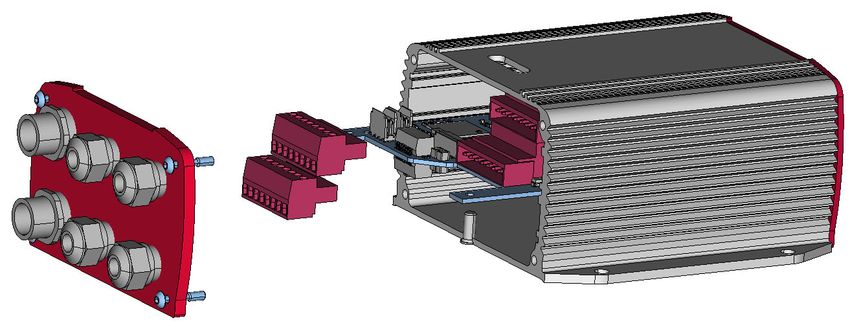
Operating Instruction EMGZ492.ECAT

2 Safety Information
    All safety information, operating and installation regulations listed here ensure proper
    function of the device. Safe operation of the systems requires compliance at all times.
    Noncompliance with the safety information or using the device outside of the specified
    performance data can endanger the safety and health of persons.
    Work with respect to operation, maintenance, retrofit, repair, or setting the device
    described here must only be performed by expert personnel.
2.1 Presentation of Safety Information
     2.1.1 Danger that Could Result in Minor or Moderate Injuries

                                 Danger, warning, caution
                         Type of danger and its source
                         Possible consequences of nonobservance
                         Measure for danger prevention

     2.1.2 Note Regarding Proper Function
                       Note
                       Note regarding proper operation
                       Simplification of operation
                       Ensuring function

    28.01.2021                                                                                 3
Operating Instruction EMGZ492.ECAT
2.2 General Safety Information
The function of the measuring amplifier is only ensured with the
components in the specified layout to one another. Otherwise, severe
malfunctions may occur. Thus, observe the mounting information on
the following pages.
Observe the local installation regulations.
Improper handling of the electronics module can lead to damage to
the sensitive electronics!
Do not work with a blunt tool (screw driver, pliers, etc.) on the
housing!
Use suitable grounding (grounding wrist strap, etc.) when working on
the electronics.
The devices should have a distance of at least 15 mm to one another
in the control cabinet for proper cooling.
28.01.2021 4Operating Instruction EMGZ492.ECAT
3 Product Description
3.1 Block Diagram
Figure 1: EMGZ492.ECAT block diagram EMGZ492_ECAT_BA_Manual.ai
3.2 System Description
The microprocessor-controlled measuring amplifier EMGZ492.ECAT series is used in
processing, amplifying, and relaying sensor signals in suitable form to downstream
devices. The measured force values are available via EtherCAT® and an analog voltage
output.
The measuring amplifiers are suitable for tension measurements using all FMS load
cells. Two force sensors A and B can be connected to the device. Both measuring values
are available as individual signal (A and B), as sum signal (A + B), as differential signal
|A – B| or as average value (A + B)/2 for the master controller.
3.3 Scope of Delivery
The following is included in the scope of delivery
- Measuring amplifier
- Mounting and operating instructions
The following is not included in the scope of delivery
- AC/DC power supply, minimum requirement: EMC immunity specifications
EN61000-4-2, 3, 4, 5; EN55024 light industry level, criteria A, e.g., TRAKO TXL 035-
0524D
- Cable for power supply
The following is not included in the scope of delivery, but are available as accessories
from FMS
- Patch cable with RJ45 plug (straight or 90°)
- Sensor cable for the connection of load cell and measuring amplifier
- M12 plug, D-coded
28.01.2021 5Operating Instruction EMGZ492.ECAT
4 Quick Guide/Quick Start
In these operating instructions, commissioning of the EMGZ492.ECAT amplifier is
limited to the installation procedure, offset compensation, and system calibration.
4.1 Preparations for Parameterization
- Read the operating instructions of the selected load cell carefully.
- Check your requirements on the system, such as:
o Used units in the system
o Used outputs (-10 to 10V and bus)
- Filter settings for actual force value and analog output
- Create the connection diagram for your specific system layout (see chapter
“Electrical Connection”)
4.2 Mounting Sequence
- Mount the load cells (mounting details can be obtained from the mounting
instructions of the load cells)
- Connect the load cells to the amplifier (see 4.5)
- Connect the amplifier to the supply voltage. The voltage supply must be in the range
of 18 to 36 VDC. (See 4.5)
- Perform offset compensation and calibration (see 5.1 and 5.3)
- Change the parameter settings as needed (see 7)
- Amplifier integration into the EtherCAT® network (see 8)
4.3 Mounting and Electrical Connections
Warning
To improve natural convection and keep heating of the amplifiers as
low as possible, the devices installed in a cabinet should have a
minimum distance of 15 mm.
Warning
The function of the measuring amplifier is only ensured with the
components in the specified layout to one another. Otherwise,
severe malfunctions may occur. Thus, the mounting information on
the following pages must be followed
Warning
The local installation regulations ensure the safety of electrical
systems. They are not considered in these operating instructions.
However, they must be met.
28.01.2021 6Operating Instruction EMGZ492.ECAT
4.4 Load Cell Mounting
The load cells are mounted in line with the mounting instructions of the respective
products. The mounting instructions are included with the load cells.
4.5 Electrical Connections
Two or four load cells can be connected to the EMGZ492.ECAT. When four sensors are
used, two of them have to be connected in parallel. The load cells and amplifier are
connected using a 2x2x0.25 mm2 [AWG 23] shielded, twisted cable.
4.5.1 EMGZ492.R.ECAT
Figure 2: EMGZ492.R.ECAT electrical connections
28.01.2021 7Operating Instruction EMGZ492.ECAT For easier installation, the terminal blocks can be detached from the main housing. Figure 3: Detachable terminal blocks: use a small slotted screwdriver as a lever 4.5.2 EMGZ492.W.ECAT The 4 screws of the cover with the PG glands and the M12 plug must be loosened for board access. You can slide out the board by approx. 2 cm (1 in.) and loosen the terminal blocks for easier connection of the wires. Figure 4: Pc board with removable terminal blocks EMGZ492_W_PNET_16-11.30.FCStd 28.01.2021 8
Operating Instruction EMGZ492.ECAT

Figure 5: EMGZ492.W.ECAT electrical connections         EMGZ492_ECAT_Grafik.ai
4.5.3 Ethernet Connections

Table 1: pin assignment Ethernet connection      EMGZ492_ECAT_Grafik.ai

                             Warning
                     Poor grounding can result in electric shocks for persons,
                     malfunctions of the overall system or damage to the measuring
                     amplifier! Proper grounding must always be ensured.

                   Note
                   Cable shielding may only be connected to one side of the measuring
                   amplifier. On the side of the load cell, shielding must remain open.

28.01.2021                                                                                9
Operating Instruction EMGZ492.ECAT
5 Calibration of the Measuring System
5.1 Offset Compensation
Using offset calibration, the weight of the measuring roller and the roller bearings is
compensated and the measuring system “zeroed”.
Offset compensation must always be executed prior to the actual calibration. The
measuring roller must not be loaded during the procedure.
To change the values for the offset compensation, please refer to 7.3 Acyclic Data
Traffic.
5.2 Calibration in the Amplifier (Adjusting the Gain Factor)
Calibration is used for matching the gain factor with the load cells. After calibration, the
displayed force corresponds to the force effectively affecting the material. Two
calibration methods are available. The first calibration method described here uses a
defined weight. There is also a calculation method for the gain. The weight-based
calibration method is simple and delivers more accurate results as it replicates the
material profile (see the figure below) and considers the actual circumstances in the
machine.
Figure 6: Replication of the material profile using a defined weight
Tension_Control_Solutions.ai
28.01.2021 10Operating Instruction EMGZ492.ECAT
5.3 Calibrating
To change the values for the calibration, please refer to 7.3 Acyclic Data Traffic.
- Connect the first load cell (see 4.5).
- The measuring signal must become positive for loads in measuring direction. If it is
negative, the signal lines of the affected load cells must be switches at the terminal
block (see 4.5).
- Connect the second load cell.
- The measuring signal must become positive for loads in measuring direction. If it is
negative, the signal lines of the affected load cells must be switched at the terminal
block (see 4.5).
- Insert material or rope into the machine, without weight/load.
- Perform offset compensation
- Load material or rope with a defined weight (see 5.2).
- Perform calibration
5.4 Gain
Depending on the material wound around the measuring roller, the applied force is not
relayed to the sensors 1:1. Thus, the measured force does not correspond to the
effectively applied force. To correct for this error, the measured force is amplified using
a factor. The factor that is referred to as gain or gain factor is calculated such that the
resulting force corresponds to the applied force. The gain is calculated per the following
formula:
Fsys Digit * Fact N
Gain =
Fsys N * Fact Digit
Option V05
The standard version uses a sensor feedback signal of ± 9 mV.
Measuring amplifiers with the option V05 are designed for a sensor
feedback signal of ± 2.5 mV. The other values in the following
description are identical.
Explanations
Variable Description
Fsys Digit Is the system force as binary value after the A/D converter. This value
is a constant with value 11’890. It is independent from the number of
used load cells. From the user’s point of view, this value corresponds
to an input signal of 9 mV.
The amplifier can measure up to an overload of 37 %.
Fact N Effectively applied force at the measuring system in Newtons.
28.01.2021 11Operating Instruction EMGZ492.ECAT
Fsys N Is the system force of the measuring system in Newtons. It is
determined by the number of used load cells. For one load cell, the
system force equals the nominal force of the load cell. For two
sensors, it is twice as high.
Fact Digit Measured force at the measuring system as binary value after the
A/D converter. From the user’s point of view, this value corresponds
to a voltage in mV, which is relayed by the measuring system to the
amplifier.
Example
- System force at 9 mV = 11‘890 digit
- 2 load cells with 500 N nominal force each, as per type plate; Fsys N = 2 x 500 N =
1‘000 N;
- Use of a defined weight of 50 kg (corresponds to approx. 500 N); Fact N = 500 N
- Obtain measured force with suspended weight from the PLC, e.g., Fact Digit = 4‘980
11‘890 * 500N
Gain = V = 1.194
1‘000N * 4‘980
Note
The gain factor needs to be calculated for both of the channels
individually.
5.5 Limit Value Violations
The amplifier checks the analog input and output for limit value violations. At the input,
it is checked using the input voltage, whether the load cell is mechanically overloaded
(overload test). The measuring amplifier can measure an overload of 37 %. At the
output, it is checked, whether the output voltage depending on the amplified input
signal will be above or below the physically possible value. In this case, an overflow
and/or underflow is present.
5.5.1 Overload Test
The overload test is performed using the raw value read on the ADC. It has thus not
related to any force and can be applied independently from the system force to every
load cell.
Test rule:
The FMS load cells deliver 9 mV at the output under nominal force load. In the case of a
load up to the mechanical stop, approx. 12.4 mV are output. These values apply, if the
load cell is loaded in normal operating direction (red point). In reverse direction, the
values are respectively negative. The amplifier checks overload in both directions.
28.01.2021 12Operating Instruction EMGZ492.ECAT
The limit value for overload is fixed set to 12 mV and/or -12 mV. If one of these limit
values is reached, the overload status bit is set. The bit is removed again, as soon as the
raw value is 0.5 mV below and/or above the triggering limit value.
5.5.2 Overflow and Underflow Test
The overflow and underflow test is performed with the output value that is relayed to the
DAC, calculated from the gain. If the output value exceeds the maximum possible value,
an overflow is present. If it undercuts the minimum possible value, an underflow is
present.
Test rule
The output voltage is between 0 and +10 V. A hysteresis of +/-10 digits is used for the
test so that the error bits do not trigger for every small over- and/or underflow. Thus, the
overflow triggers, when the theoretically calculated output value of 10.05 V is reached.
For underflow, the value is 0.05 V. When these limit values are reached, the respective
bits are set in the status. The bits are removed, as soon as the output value is within the
valid range again (above 0.05 V and below 9,95 V).
5.6 Description of the LEDs
LED Meaning
Off: no connection to the preceding
EtherCAT module
On: LINK: connection to the
L/A IN preceding EtherCAT module
Flashing: ACT: Communication with
the preceding EtherCAT module
Off: no connection to the following
EtherCAT module
On: LINK: connection to the
L/A OUT following EtherCAT module
Flashing: ACT: Communication with
the following EtherCAT module
Off: Status of the EtherCAT module
is Init
Flashes quickly: Status of the
EtherCAT module is pre-operational
RUN Flashes slowly: Status of the
EtherCAT module is safe-operational
On: Status of the EtherCAT module
is operational
Illuminates in red if no RJ45 plug is
connected.
ERR Flashes red if communication with
EMGZ492.R.ECAT EMGZ492.W.ECAT the PLC is interrupted.
Illuminates in green as soon as the
RDY voltage supply is connected and the
processor is started.
Figure 7: Signal LEDs on EMGZ492.ECAT EMGZ492_ECAT_Grafik.ai
28.01.2021 13Operating Instruction EMGZ492.ECAT
6 Integration into the EtherCAT® Network
The measuring amplifiers of the EMGZ492.ECAT series can operate in an EtherCAT®
network. Here, the amplifier operates as EtherCAT® slave with an EtherCAT® master (e.g.
TwinCAT.
6.1 EtherCAT® Interface
EtherCAT® is supported. The respective communication profile is selected by the
EtherCAT® master via the ESI. The EMGZ492.ECAT transfers the actual value in digit and
the status/error byte. In addition, parameters, such as offset actual value, gain actual
value, filter actual value, filter analog output, as well as scaling analog output can be
adjusted.
6.2 System Start
Module parameters are not supported.
6.3 Data Exchange
The EMGZ492.ECAT uses the communication types typical in EtherCAT®. Cyclic data
traffic is used for the fast transmission of measured data. Acyclic data traffic is used for
parameterization. Cyclic data traffic is used for transmitting the limit value violations.
28.01.2021 14Operating Instruction EMGZ492.ECAT
7 Configuration
The EMGZ492.ECAT can be configured via EtherCAT®.
7.1 Parameter Description
Parameter
Name Description
Unit Here you select which unit of measurement is used. The
label located on the sensor will indicate the nominal
force in Newtons.
Note:
This input will also affect the unit of the cyclic process
data.
If lb (pound) is selected, the system switches from metric
to imperial measuring units.
Selection N, kN, lb, g, kg
Specified value N
Low-pass filter active A Here, the status of the low-pass filter active value for the
force sensor A is indicated.
This parameter cannot be accessed via the web interface.
Min. 0
Max. 1
Specified value 1
0 = no, inactive, 1 = yes, active
Offset A The values determined with the “Offset Compensation”
procedure are stored in the form of a digital value in the
[Offset] parameter. The value is used for compensating
for the roller weight of force sensor A.
Min. -16’000
Max. 16’000
Specified value 0
Gain A The gain factor ensures that the displayed force matches
the effective force on sensor A.
Min. 0.100
Max. 20.000
Specified value 1.000
28.01.2021 15Operating Instruction EMGZ492.ECAT
Nominal force A The nominal force indicates the measuring capacity of
force sensor A. E.g., if a 500 N load cells is installed 500
N must be entered.
Unit N
Min. 1.00
Max. 200‘000.00
Specified value 1‘000.00
Limit frequency low- The amplifier features a low-pass filter that filters the
pass filter actual value measured value is relayed via EtherCAT®. This filter is
A used for suppressing undesired interference signals that
are superimposed on the measuring signal. Using this
parameter, the limit frequency of the filter of force sensor
A is adjusted. The lower the limit frequency, the slower
the measuring value.
This low-pass filter is independent from the output filter.
Unit Hz
Min. 0.1
Max. 200.0
Specified value 10.0
Low-pass filter active B Here, the status of the low-pass filter active value for the
force sensor B is indicated.
This parameter cannot be accessed via the web interface.
Min. 0
Max. 1
Specified value 1
0 = no, inactive, 1 = yes, active
Offset B The values determined with the “Offset Compensation”
procedure are stored in the form of a digital value in the
[Offset] parameter. The value is used for compensating
for the roller weight of force sensor B.
Min. -16’000
Max. 16’000
Specified value 0
Gain B The gain factor ensures that the displayed force matches
the effective force on sensor B.
Min. 0.100
Max. 20.000
Specified value 1.000
28.01.2021 16Operating Instruction EMGZ492.ECAT
Nominal force B The nominal force indicates the measuring capacity of
force sensor B. E.g., if a 500 N load cells is installed 500
N must be entered.
Unit N
Min. 1.00
Max. 200‘000.00
Specified value 1‘000.00
Limit frequency low- The amplifier features a low-pass filter that filters the
pass filter actual value measured value is relayed via EtherCAT®. This filter is
B used for suppressing undesired interference signals that
are superimposed on the measuring signal. Using this
parameter, the limit frequency of the filter of force sensor
B is adjusted. The lower the limit frequency, the slower
the measuring value.
This low-pass filter is independent from the output filter.
Unit Hz
Min. 0.1
Max. 200.0
Specified value 10.0
Low-pass filter analog Here, the status of the low-pass filter for the analog
output active output is indicated.
Min. 0
Max. 1
Specified value 1
0 = no, inactive, 1 = yes, active
Limit frequency low- The amplifier features a low-pass filter that filters the
pass filter analog signal of the analog voltage output. This filter is used for
output suppressing undesired interference signals. Using this
parameter, the limit frequency of the filter is adjusted.
This low-pass filter is independent from the EtherCAT®
filter.
Unit Hz
Min. 0.1
Max. 200.0
Specified value 10.0
28.01.2021 17Operating Instruction EMGZ492.ECAT
Analog output scaling This parameter determines, for which force the analog
output outputs its maximum voltage (10 V).
Note:
If lb (pound) is selected, the system switches from metric
to imperial measuring units.
Unit N
Min. 0.1
Max. 200‘000.00
Specified value 1‘000.00
7.2 Cyclic Data Traffic
After a successful system start the EtherCAT® master and the assigned EtherCAT®
slaves can exchange cyclic process data. The table below shows the measured data and
how they are transmitted.
Parameter
Name Description
Actual value A in ADC Value read in via the A/D converter.
Data type int (signed 16 bit)
Value range -16384 to 16383
Value format ±#####
The value is interpreted as integer without decimal place.
E.g. 1000 = 1000 ADC raw value
Actual value A in Filtered actual value converted into Newton
Newton Data type long (signed 32 bit)
Value range ±200‘000‘000
Value format ±######.###
The value is interpreted as decimal number with 3
decimal places. E.g. 1500 = 1.500 N (1.5 N)
Unit N
Actual value A in Filtered actual value converted into pound.
pound Data type long (signed 32 bit)
Value range ±200‘000‘000
Value format ±######.###
The value is interpreted as decimal number with 3
decimal places. E.g. 224820 = 224.820 lb (224.82 lb)
Unit lb
28.01.2021 18Operating Instruction EMGZ492.ECAT
Actual value A in unit Filtered actual value converted into configured unit.
Data type long (signed 32 bit)
Value range ±200‘000‘000
Value format ±#######.### for N, kN, kg, or lb
The value is interpreted as decimal number with 3
decimal places. E.g. unit set to kN 100000 = 100.000 kN
(100kN)
Value format ±#########.# for g
The value is interpreted as decimal number with 1
decimal place. E.g. unit set to g 12340 = 1234.0 g (1234
g)
Unit N, kN, g, kg, or lb
Actual value B in ADC Value read in via the A/D converter.
Data type int (signed 16 bit)
Value range -16384 to 16383
Value format ±#####
The value is interpreted as integer without decimal place.
E.g. 1000 = 1000 ADC raw value
Actual value B in Filtered actual value converted into Newton
Newton Data type long (signed 32 bit)
Value range ±200‘000‘000
Value format ±######.###
The value is interpreted as decimal number with 3
decimal places. E.g. 1500 = 1.500 N (1.5 N)
Unit N
Actual value B in Filtered actual value converted into pound.
pound Data type long (signed 32 bit)
Value range ±200‘000‘000
Value format ±######.###
The value is interpreted as decimal number with 3
decimal places. E.g. 224820 = 224.820 lb (224.82 lb)
Unit lb
28.01.2021 19Operating Instruction EMGZ492.ECAT
Actual value B in unit Filtered actual value converted into configured unit.
Data type long (signed 32 bit)
Value range ±200‘000‘000
Value format ±#######.### for N, kN, kg, or lb
The value is interpreted as decimal number with 3
decimal places. E.g. unit set to kN 100000 = 100.000 kN
(100 kN)
Value format ±#########.# for g
The value is interpreted as decimal number with 1
decimal place. E.g. unit set to g 12340 = 1234.0 g (1234
g)
Unit N, kN, g, kg, or lb
Actual value A + B in Filtered actual sum value converted into configured unit.
unit Data type long (signed 32 bit)
Value range ±200‘000‘000
Value format ±#######.### for N, kN, kg, or lb
The value is interpreted as decimal number with 3
decimal places. E.g. unit set to kN 100000 = 100.000 kN
(100 kN)
Value format ±#########.# for g
The value is interpreted as decimal number with 1
decimal place. E.g. unit set to g 12340 = 1234.0 g (1234
g)
Unit N, kN, g, kg, or lb
Actual value |A - B| in Filtered actual differential value converted into
unit configured unit.
Data type long (signed 32 bit)
Value range ±200‘000‘000
Value format ±#######.### for N, kN, kg, or lb
The value is interpreted as decimal number with 3
decimal places. E.g. unit set to kN 100000 = 100.000 kN
(100 kN)
Value format ±#########.# for g
The value is interpreted as decimal number with 1
decimal place. E.g. unit set to g 12340 = 1234.0 g (1234
g)
Unit N, kN, g, kg, or lb
28.01.2021 20Operating Instruction EMGZ492.ECAT
Actual value (A + B)/2 Filtered actual average value converted into configured
in unit unit.
Data type long (signed 32 bit)
Value range ±200‘000‘000
Value format ±#######.### for N, kN, kg, or lb
The value is interpreted as decimal number with 3
decimal places. E.g. unit set to kN 100000 = 100.000 kN
(100 kN)
Value format ±#########.# for g
The value is interpreted as decimal number with 1
decimal place. E.g. unit set to g 12340 = 1234.0 g (1234
g)
Unit N, kN, g, kg, or lb
Status The status contains information about the current
process and operating condition.
Every bit represents a separate event. The condition is
active, if the bit is set.
Data type byte (unsigned 8 bit)
Bit 0 Overload (LSB) A
Bit 1 Overload (LSB) B
Bit 2 Analog output overflow
Bit 3 Analog output underflow
7.3 Acyclic Data Traffic
After a successful system start the EtherCAT® master the assigned EtherCAT® slaves
can exchange acyclic requirement data. The following table shows the parameters and
commands and how they are transmitted using acyclic data traffic.
To address the parameter group "Force Values Configuration" the index 0x2800 and sub
index 0x01 to 0x08 have to be used.
28.01.2021 21Operating Instruction EMGZ492.ECAT
Parameter
Index 0x2800 Description
Sub index
0x01 Unit
Access type R/W
Parameter command unit
Data type byte (unsigned 8 bit)
Value range 0 to 4
0=N; 1=kN; 2=lb; 3=g; 4=kg
Value format #
0x02 Offset A
Access type R/W
Parameter command offset
Data type int (unsigned 16 bit)
Value range -16‘000 to 16‘000
Value format ±#####
0x03 Gain A
Access type R/W
Parameter command gain
Data type int (unsigned 16 bit)
Value range 100 to 20‘000
Value format ##.###
0x04 Nominal force A
The nominal force is the maximum permissible force of
the used measuring system.
Access type R/W
Parameter command Nominal force
Data type long (unsigned 32 bit)
Value range 0 to 200‘000‘000
Value format ######.###
Unit N
28.01.2021 22Operating Instruction EMGZ492.ECAT
0x05 Low-pass filter active A
Switch the low-pass filter actual value on or off; 0 = off; 1
= on.
Not remanent: The adjusted value is lost on a restart! This
filter is switched on after a restart.
This parameter cannot be accessed via the web interface.
Access type R/W
Parameter command low-pass filter actual value
active (EtherCAT®)
Data type byte (unsigned 8 bit)
Value range 0 to 1
Value format #
0x06 Limit frequency low-pass filter actual value A
Limit frequency of the low-pass filter for the actual value
outputted via EtherCAT®.
Access type R/W
Parameter command limit frequency low-pass filter
actual value (EtherCAT®)
Data type int (unsigned 16 bit)
Value range 1 to 2‘000
Value format ###.#
Unit Hz
0x07 Offset adjustment A
Determine and store offset. The system is set to zero
without material tension.
Access type W
Parameter command offset adjustment
Data type byte (unsigned 8 bit)
Value range 0 to 1
Value format #
28.01.2021 23Operating Instruction EMGZ492.ECAT
0x08 Calibration A
Calibrates the amplifier to the weight in Newton, which is
handed over here. It must match the suspended weight.
Access type W
Parameter command calibration
Data type long (signed 32 bit)
Value range 0 to 200‘000‘000
Value format ######.###
Unit N
0x09 Offset B
Access type R/W
Parameter command offset
Data type int (unsigned 16 bit)
Value range -16‘000 to 16‘000
Value format ±#####
0x0A Gain B
Access type R/W
Parameter command gain
Data type int (unsigned 16 bit)
Value range 100 to 20‘000
Value format ##.###
0x0B Nominal force B
The nominal force is the maximum permissible force of
the used measuring system.
Access type R/W
Parameter command Nominal force
Data type long (unsigned 32 bit)
Value range 0 to 200‘000‘000
Value format ######.###
Unit N
28.01.2021 24Operating Instruction EMGZ492.ECAT
0x0C Low-pass filter active B
Switch the low-pass filter actual value on or off; 0 = off; 1
= on.
Not remanent: The adjusted value is lost on a restart! This
filter is switched on after a restart.
Access type R/W
Parameter command low-pass filter actual value
active (EtherCAT®)
Data type byte (unsigned 8 bit)
Value range 0 to 1
Value format #
0x0D Limit frequency low-pass filter actual value B
Limit frequency of the low-pass filter for the actual value
outputted via EtherCAT®.
Access type R/W
Parameter command limit frequency low-pass filter
actual value (EtherCAT®)
Data type int (unsigned 16 bit)
Value range 1 to 2‘000
Value format ###.#
Unit Hz
0x0E Offset adjustment B
Determine and store offset. The system is set to zero
without material tension.
Access type W
Parameter command offset adjustment
Data type byte (unsigned 8 bit)
Value range 0 to 1
Value format #
28.01.2021 25Operating Instruction EMGZ492.ECAT
0x0F Calibration B
Calibrates the amplifier to the weight in Newton, which is
handed over here. It must match the suspended weight.
Access type W
Parameter command calibration
Data type long (signed 32 bit)
Value range 0 to 200‘000‘000
Value format ######.###
Unit N
Explanation of access types: R = Read, W = Write, R/W = Read and Write.
To address the parameter group "Analog Output Configuration" you have to use index
0x2820 and subindex 0x01 to 0x04.
Parameter
Index 0x2820 Description
Sub index
0x01 Output value
0 = (A +B)/2
1=A+B
2 = |A - B|
3=A
4=B
0x02 Analog output scaling
Determines, at which force the analog output outputs the
maximum value of 10 V.
Access type R/W
Parameter command analog output scaling
Data type long (unsigned 32 bit)
Value range 100 to 200‘000‘000
Value format ######.###
Unit N
28.01.2021 26Operating Instruction EMGZ492.ECAT
0x03 Low-pass filter analog output active
Switch the low-pass filter analog output on or off; 0 = off;
1 = on.
Not remanent: The adjusted value is lost on a restart! This
filter is switched on after a restart.
Access type R/W
Parameter command low-pass filter analog output
active
Data type byte (unsigned 8 bit)
Value range 0 to 1
Value format #
0x04 Limit frequency low-pass filter analog output
Limit frequency of the low-pass filter for the actual value
outputted via the analog output.
Access type R/W
Parameter command limit frequency low-pass filter
analog output
Data type int (unsigned 16 bit)
Value range 1 to 2‘000
Value format ###.#
Unit Hz
Explanation of access types: R = Read, W = Write, R/W = Read and Write.
28.01.2021 27Operating Instruction EMGZ492.ECAT
8 EtherCAT® Communication
The acyclic data exchange is provided according to the ESI file
8.1 Services and Protocols
The following services and protocols are used:
- SDO client and server side protocol (CoE)
- File Access over EtherCAT®(FoE)
All other services required for EtherCAT® are permissible as well.
The services above can be used with the EMGZ492.ECAT at any time.
28.01.2021 28Operating Instruction EMGZ492.ECAT 9 Dimensions Figure 8: EMGZ492.R.ECAT housing for DIN rail mounting EMGZ492_ECAT_Grafik.ai Figure 9: EMGZ492.W.ECAT housing for wall mounting EMGZ492_ECAT_Grafik.ai 28.01.2021 29
Operating Instruction EMGZ492.ECAT

10 Technical Data
      Technical data
     Number of channels                 2 channel for 2 or 4 sensors
     Excitation voltage                 5 VDC
     Sensor feedback signal             ± 9 mV (max. 12.5 mV)
                                        Option V05 ± 2.5 mV
     A/D converter resolution           ± 32‘768 digit (16 bit)
     D/A converter resolution           0 to 4‘096 (12 bit)
     Measuring inaccuracy               < 0.05 % FS
     Connector for interface            EMGZ 492.R.ECAT: 2 x RJ-45
                                        EMGZ 492.W.ECAT: 2 x M 12 4-pole, D-coded
     Parameterization                   via EtherCAT®
     Protection class                   IP 20 (.R version)
                                        IP 65 (.W version)
     Power supply                       24 VDC (18 to 36 VDC)
     Power consumption                  5W
     Temperature range                  –10 to +50 °C (14 to 122 °F)
     Weight                             370 g / 0.82 lbs (.R version);
                                        470 g / 1.04 lbs (.W version)

   28.01.2021                                                                       30
Operating Instruction EMGZ492.ECAT
EtherCAT® characteristics
Cycle time ≥ 1 ms in Free Run Mode
Baud rate 100 Mbit /s
Cyclic process data PDO with fixed mapping
Acyclic communication SDO Master-Slave
Supported protocols SDO client and server side protocol (CoE); File
Access over EtherCAT (FoE)
CoE (CAN application layer over SDO Upload, SDO Download, SDO Information
EtherCAT) Service (Object Dicti onary)
Mailbox Size Fix length of 128 Byte
SII (Slave Information Interface) 4 kB
Type Complex Slave
FMMUs 8
SYNC Manager 4
Explicit Device Identification Set Device Identification by Configuration Tool
28.01.2021 31Operating Instruction EMGZ492.ECAT
FMS Force Measuring Systems AG FMS USA, Inc. FMS (UK) FMS Italy
Aspstrasse 6 2155 Stonington Avenue Suite 119 Highfield, Atch Lench Road Via Baranzate 67
8154 Oberglatt (Switzerland) Hoffman Estates,, IL 60169 (USA) Church Lench 20026 Novate Milanese
Tel. +41 44 852 80 80 Tel. +1 847 519 4400 Evesham WR11 4UG (Great Britain) Phone +39 02 39487035
Fax +41 44 850 60 06 Fax +1 847 519 4401 Tel. 01386 871023 Fax +39 02 39487035
info@fms-technology.com fmsusa@fms-technology.com Fax 01386 871021 fmsit@fms-technology.com
www.fms-technology.com fmsuk@fms-technology.com
28.01.2021 32You can also read