Industrial pressure controller Model CPC4000
←
→
Page content transcription
If your browser does not render page correctly, please read the page content below
Calibration

Industrial pressure controller
Model CPC4000
                                                                                                             WIKA data sheet CT 27.40

                                                                      for further approvals see
                                                                      page 3

 Applications
■■ Oil and gas industry
■■ Industry (laboratory, workshop and production)
■■ Transmitter and pressure gauge manufacturers
■■ Calibration service companies and service industry

 Special features
■■ Pressure ranges: -1 ... 210 bar (-15 ... 3,045 psi)                Industrial pressure controller, model CPC4000
■■ Control speed 10 s
■■ Control stability < 0.005 % FS
■■ Accuracy to 0.02 % IS (IntelliScale)
■■ Precision 0.008 % FS

Description
Design                                                                Functionality
The model CPC4000 industrial pressure controller                      Maximum ease-of-use is achieved through the touchscreen
offers a broad pressure range from -1 … 210 bar                       and the simple and intuitive menu navigation. In addition,
(-15 … 3,045 psi). This instrument is available as a desktop          the large number of menu languages add to its operability.
or as a 19" rack-mounting kit.                                        The instrument can have up to two internal pressure sensors
It can be installed with up to two reference pressure sensors         and the ranges for each reference pressure sensor are
and an optional barometer. The barometer can be used                  determined by the customer within the allowable range.
to display the barometric pressure or to emulate gauge or
absolute pressure.                                                    Depending on the application, the operator can choose
                                                                      between three set-point entry methods:
Application                                                           1) Direct entry of the pressure value (set point) which will be
Since the controller offers an accuracy of up to 0.02 % IS-50,           controlled via touchscreen keypad.
and controls pressure with a high stability, it is particularly       2) Define steps to reach the desired pressure value by either
suited as a production tool for transmitter manufacturing,               defining fixed pressure increments or a percentage of
a calibration and maintenance tool for pressure measuring                span value.
instruments or as a factory/working standard for the                  3) User-defined programmable test sequences.
calibration of all types of pressure measuring instruments.
The leak test and burst test special applications allow
CPC4000 to be used as a pressure line testing equipment.
The optional automatic contamination prevention system
make the CPC4000 an ideal solution in oil and gas plants.

WIKA data sheet CT 27.40 ∙ 08/2019                                                                                       Page 1 of 12

Data sheets showing similar products and accessories:
Modular pressure controller; model CPC6050; see data sheet CT 27.62
High-end pressure controller; model CPC8000; see data sheet 28.01
WIKA-Cal calibration software; see data sheet CT 95.10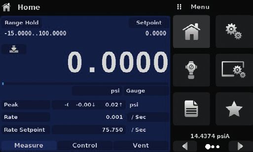
Software                                                                                           Complete test and calibration systems
The WIKA-Cal calibration software enables the convenient                                           On request, complete mobile or stationary test systems can
calibration of pressure measuring instruments and the                                              be manufactured. There is an IEEE-488.2, RS-232, USB
generation of test certificates. Additionally, the instrument                                      and an Ethernet interface for communication with other
can also be remotely controlled using the serial command                                           instruments, and thus the instrument can be integrated into
formats, the Mensor standard, SCPI or further optional                                             existing systems.
command sets are available.

Specifications
Model CPC4000
 Reference pressure sensors model CPR4000
 Pressure range                                    Standard                                                               Optional
     Accuracy 1)                                   0.02 % FS 2)                                                           0.02 % IS-50 3)
     Gauge pressure 4)                             0 ... 0.35 to 0 ... 210 bar                                            0 ... 1 to 0 ... 210 bar
                                                   (0 ... 5 to 0 ... 3,045 psi)                                           (0 ... 15 to 0 ... 3,045 psi)
     Bi-directional 4)                             -0.17 ... 0.17 to -1 ... 210 bar                                       -1 ... 10 to -1 ... 210 bar
                                                   (-2.5 ... 2.5 to -15 ... 3,045 psi)                                    (-15 ... 145 to -15 ... 3,045 psi)
     Absolute pressure 5)                          0 ... 1 to 0 ... 211 bar abs.                                          0 ... 1 to 0 ... 211 bar abs.
                                                   (0 ... 15 to 0 ... 3,060 psi abs.)                                     (0 ... 15 to 0 ... 3,060 psi abs.)
     Precision 6)                                  0.008 % FS                                                             0.008 % FS
     Calibration interval                          365 days                                                               365 days
 Optional barometric reference
     Function                                      The barometric reference can be used to switch pressure types 7), absolute  gauge. With gauge
                                                   pressure sensors, the measuring range of the sensors must begin with -1 bar (-15 psi) in order to carry
                                                   out a complete absolute pressure emulation.
     Measuring range                               552 ... 1,172 mbar abs. (8 ... 17 psi abs.)
     Accuracy    1)                                0.02 % of reading
 Pressure units                                    39 and two freely programmable
1)   It is defined by the total measurement uncertainty, with the coverage factor (k = 2) and includes the intrinsic performance of the instrument, the measurement uncertainty of the reference
     instrument, long-term stability, influence of ambient conditions, drift and temperature effects over the compensated range with recommended zero point adjustment every 30 days.
2)   FS = Full span = end of measuring range - start of measuring range
3)   0.02 % IS-50 accuracy: Between 0 ... 50 % of the full scale, the accuracy is 0.02 % of half of the full scale value and between 50 ... 100 % of the full scale, the accuracy is 0.02 % of
     reading.
4)   For pressure ranges from ≥ 100 ... ≤ 138 bar [≥ 1,500 ... ≤ 2,000 psi] gauge will be sealed gauge sensor.
5)   The minimum calibrated range of absolute sensor(s) is 600mTorr.
6)   It is defined as the combined effects of linearity, repeatability and hysteresis throughout the stated compensated temperature range.
7)   For a pressure type emulation, we recommend a native absolute pressure sensor, since the zero point drift can be eliminated through a zero point adjustment.

 Base instrument
 Instrument
     Instrument version                                 Standard: desktop case
                                                        Option: 19" rack-mounting kit
     Dimensions                                         See technical drawings
     Weight                                             approx. 12.7 kg (28 lbs) incl. all internal options
     Warm-up time                                       approx. 15 min
 Display
     Screen                                             7.0" colour LC display with resistive touchscreen
     Resolution                                         4 ... 6 digits depending on range and units

WIKA data sheet CT 27.40 ∙ 08/2019                                                                                                                                             Page 2 of 12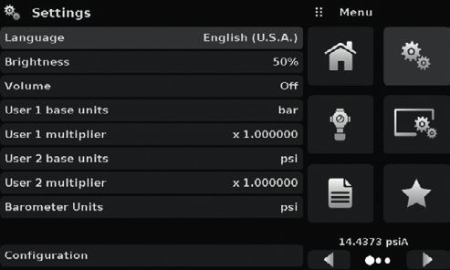
Base instrument
 Connections
     Pressure connections                                4 ports with 7/16"- 20 F SAE, 1 port with 1/8" F NPT and 1 port with 10-32 UNF female
     Filter elements                                     The instrument has a 40-micron filters on all pressure ports.
     Pressure port adapters                              Standard: without
                                                         Option: 6 mm tube fitting, 1/4" tube fitting, 1/4" female NPT fittings, 1/8" female NPT fittings or 1/8"
                                                         female BSP fittings
     Barometer port adapters                             Standard: barb fitting
                                                         Option: 6 mm tube fitting, 1/4" tube fitting
     Permissible pressure media                          Dry, clean air or nitrogen (ISO 8573-1:2010 class 5.5.4 or better)
     Wetted parts                                        Aluminium, brass, 316 and 316L stainless steel, Buna N, FKM/FPM, PCTFE, PEEK, PTFE, PPS,
                                                         glass-filled epoxy, RTV, ceramic, silicone, silicone grease, Urethane
     Overpressure protection                             Safety relief valve fixed to reference pressure sensor and adjusted to specific customised
                                                         measuring range
 Permissible pressure
     Supply port                                         110 % FS or 0.69 bar (10 psi), whichever is greater
     Measure/Control port                                max. 105 % FS
 Voltage supply
     Power supply                                        AC 100 ... 120 V, 50/60 Hz; AC 220 ... 240 V, 50/60 Hz
     Power consumption                                   max. 150 VA
 Permissible ambient conditions
     Storage temperature                                 -20 ... +70 °C (-4 ... +158 °F)
     Humidity                                            5 … 95 % r. h. (relative humidity non-condensing)
     Compensated temperature range                       15 ... 45 °C (59 ... 113 °F)
     Mounting position                                   horizontal
 Control parameter
     Control stability                                   < 0.005 % FS of the primary range in precision mode
     Control mode                                        precision, high speed and customised
     Control time                                        10 s (regarding a 10 % FS pressure increase above atmosphere in a 50 ml test volume)
     Control range                                       0 ... 100 % FS
     Min. control pressure                               0.0017 bar (0.025 psi) over exhaust pressure or 0.05 % FS whichever is greater
     Overshoots                                          < 1 % FS in high-speed control mode (typical < 0.1 % FS in precision control mode)
     Test volume                                         50 ... 1,000 ccm
 Communication
     Interface                                           Ethernet, IEEE-488, USB, RS-232
     Command sets                                        Mensor, WIKA SCPI, others optional
     Response time                                       approx. 100 ms
     Internal program                                    up to 24 sequences with up to 99 steps each

Approvals
 Logo             Description                                                                                                                                Country
                  EU declaration of conformity                                                                                                               European Union
                  ■■ EMC directive 8)
                      EN 61326-1 emission (group 1, class A) and interference immunity (industrial application)
                  ■■ Low voltage directive
                  ■■ RoHS directive

                  EAC (option)                                                                                                                               Eurasian Economic
                  ■■ EMC directive                                                                                                                           Community
                  ■■ Low voltage directive

8)   Warning! This is class A equipment for emissions and is intended for use in industrial environments. In other environments, e.g. residential or commercial installations, it can interfere
     with other equipment under certain conditions. In such circumstances the operator is expected to take the appropriate measures.

WIKA data sheet CT 27.40 ∙ 08/2019                                                                                                                                               Page 3 of 12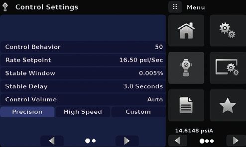
Logo            Description                                                                                               Country
                 GOST (option)                                                                                             Russia
                 Metrology, measurement technology
                 KazInMetr (option)                                                                                        Kazakhstan
                 Metrology, measurement technology
 -               MTSCHS (option)                                                                                           Kazakhstan
                 Permission for commissioning
                 Uzstandard (option)                                                                                       Uzbekistan
                 Metrology, measurement technology
                 BelGIM (option)                                                                                           Belarus
                 Metrology, measurement technology

Certificates
 Certificate
 Calibration 1)                                             Standard: A2LA calibration certificate (standard on factory)
                                                            Option: DKD/DAkkS calibration certificate
 Recommended recalibration interval                         1 year (dependent on conditions of use)

Approvals and certificates, see website

 Working ranges of the controller modules

 Bi-directional or gauge pressure [bar (psi)] 2)
 -1 (-15)                     0                           3.4 (50)                         10 (150)     100 (1,500)                     210 (3,045)

         LPSVR MODULE ±0.17 bar (±2.5 psi) 3)

                         MPSVR MODULE ±0.35 bar (±5 psi) 3)

                                   HPSVR MODULE -1 ... 5 bar (-15 ... +75 psi) 3)

                                                           EPSVR MODULE -1 ... 10 bar (-15 ... +150 psi) 3)

 Absolute pressure [bar (psi)] 2)
 0                                                        4.4 (60)                         11 (165)     101 (1,515)                     211 (3,060)

        LPSVR MODULE 0 ... 1 bar (0 ... 15 psi) 3)

                      MPSVR MODULE 0 ... 1 bar (0 ... 15 psi) 3)

                                     HPSVR MODULE 0 ... 6 bar (0 ... +90 psi) 3)

                                                              EPSVR MODULE 0 ... 11 bar (0 ... 165 psi) 3)

1)   Calibration in a horizontal position/operating position.
2)   Mixing of absolute pressure and gauge pressure sensors in a module is not possible.
3)   Smallest acceptable sensor range

     For controlling absolute pressure a vacuum pump connected at the exhaust port is required.

WIKA data sheet CT 27.40 ∙ 08/2019                                                                                                      Page 4 of 12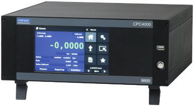
Dimensions in mm (in)

Desktop case
 Front view

                                                                     133.5 (5.26)
                                     345.6 (13.61)                    11.3 (0.45)

 Side view (left)

                                     380.5 (14.98)

                                      388.1 (15.28)

19" rack-mounting kit, front view
                                                                                                              177.1 (6.97)
                                                                                               101.6 (4.00)

                                                                                    3 (0.12)
                                                     468.1 (18.43)

                                                     481.9 (18.97)

WIKA data sheet CT 27.40 ∙ 08/2019                                                                             Page 5 of 12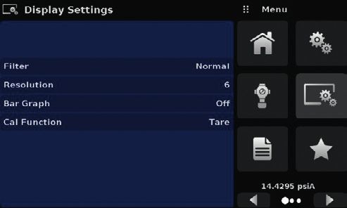
Electrical and pressure connections - rear view

                                                             1         2                    3               4       5

            15
                                                                   BAROMETRIC
                                                                   REFERENCE
                                                                                                                            6
                           SUPPLY                                EXHAUST

            14                                                                      FAN DO NOT COVER!

                                                                 VENT (ATM)

                                     MEASURE/CONTROL   REF

                                           13          12           11                    10            9       8       7

1   Exhaust port (7/16-20 UNF)                                                  9     USB interface (host) for service

2   Barometric reference port (10-32 UNF)                                       10    Automatic CPC connector

3   Fan                                                                         11    Vent (ATM)

4   IEEE-488 interface                                                          12    Reference port (7/16-20 UNF)

5   RS-232 interface                                                            13    Measure/Control port (7/16-20 UNF)

6   Ethernet port                                                               14    Supply port (7/16-20 UNF)

7   Power supply                                                                15    Instrument label

8   USB interface (instrument) for remote communication

WIKA data sheet CT 27.40 ∙ 08/2019                                                                                              Page 6 of 12
Touchscreen and intuitive operator interface
Shortly after power-up, the standard main screen (see following picture) is displayed. In this menu screen, one can switch
between the operating modes using the buttons MEASURE, CONTROL and VENT. The instrument is a precision pressure
controller, whose setup (incl. optional functions) can be easily configured via the touchscreen.

Standard desktop/main screen

                        20
                                                                                                       1
                              19
                        18                                                                             2
                              17
                                                                                                       3
                        16
                              15
                                                                                                       4
                        14

                              13                                                                       5

                                                                                                       6
                              12
                                                                                                       7
                                                                                                       8

                                           11         10              9

 1   Home application                                            11   MEASURE
                                                                      In measure mode, the pressure present at the Measure/
 2   General settings
                                                                      Control port is measured with high accuracy (if you
 3   Control settings                                                 switch directly from CONTROL to MEASURE mode, the
                                                                      last controlled pressure in the connected test assembly
 4   Display settings
                                                                      will be maintained/locked).
 5   Programs                                                    12   Auxiliary displays either peak, rate or alternate units

 6   Favourites                                                  13   Current pressure unit and type

 7   Barometric pressure reading (optional)                      14   Optional bar graph

 8   Menu scroll features forward / back                         15   Current measuring value

 9   VENT                                                        16   Zero or Tare function
     Immediately vents the system, including the test
                                                                 17   Entered set point
     assembly connected to the Measure/Control port, to
     atmosphere.                                                 18   Pressure range of the sensors
10   CONTROL
                                                                 19   Selection of the active sensor or auto-range
     In control mode the instrument provides a highly
     accurate pressure at the Measure/Control port of the        20   Current application name
     respective channel in accordance with the desired set
     point.

WIKA data sheet CT 27.40 ∙ 08/2019                                                                                    Page 7 of 12
Simple instrument configurations
A) General settings of the instrument
1 Instrument language, screen brightness and volume
settings
1 2 User-defined measurement units
3 Unit for the optional barometer
4 Multiple user-specific configurations to create and
2
save for ease of access
3
4
B) Control settings of the instrument
5 Control behavior between low overshoot and high
speed
6 The control rate can be entered by the user as a
5 factor of current units/sec.
6 7 The stability of the control can be defined by the
user by setting the stable window as “% FS” and by
7
setting the stable delay.
8 8 The pressure control volume can be adjusted by
the user or set to “Auto” for dynamic automatic
detection
C) Sensor settings and auxiliary display settings of the instrument
9 Electronic filter to smooth the pressure
measurement
10 The resolution of the sensor display can be
9 changed
10 11 Switching the bar graph on or of
11
12 Easy zeroing and tare features
12
WIKA data sheet CT 27.40 ∙ 08/2019 Page 8 of 12Automatic Contamination Prevention System (A-CPS)
Specifications
Model A-CPS
Base instrument
Operating conditions
Maximum operating pressure 211 bar (3,065 psi)
Maximum operating temperature 80 °C (176 °F)
Voltage supply
Power supply DC 12 V
Power consumption 13 VA
Pressure connection
To the M/C port of CPC4000 1 port with 1/4" tube adapted to 7/16"- 20 F SAE
To the test item 2 ports
Standard: 7/16" - 20 F SAE
Option: 6 mm tube fitting, 1/4" tube fitting, 1/4" female NPT fittings, 1/8" female NPT fittings or 1/8"
female BSP fittings
Dimensions
Dimensions (W x H x D) 139.7 x 266.7 x 139.7 mm (5.5 x 10.5 x 5.5 in)
Weight 3.9 kg (8.8 lbs.)
A-CPS operation
Active decontamination Automatic or manual purging with CPC4000
The Automatic Contamination Prevention System, or A-CPS, The A-CPS can be driven seamlessly with the CPC4000 in
is an accessory to the CPC4000 industrial pressure controller manual or auto mode. The auto mode will engage the purge
that prevents particles, water or oil contaminants from sequence every time the controller switches from vent to
entering the instrument through the test item. The A-CPS control mode.
uses a coalescing filter and an automatically actuated vent
valve to remove all the contaminants and then stores them in The manual mode provides an option for pre-cleansing the
a transparent sump bottle for easy cleanup. system by purging the test item several times. A purge button
appears on the instrument’s home screen when the A-CPS
The A-CPS allows hassle-free operation between the test is activated. The purge button enables setting the desired
item and the CPC4000 by reducing the additional process of maximum pressure for decontaminating the test item prior
deep cleaning the instrument prior to calibration. The A-CPS to normal operation with the model CPC4000 industrial
does not require an additional power source because it is pressure controller.
controlled completely by the pressure controller itself.
The A-CPS also acts like a test gauge stand for easy
mounting and setup of the test item. This reduces the
requirement of additional manifolds and setup.
WIKA data sheet CT 27.40 ∙ 08/2019 Page 9 of 12WIKA-Cal calibration software
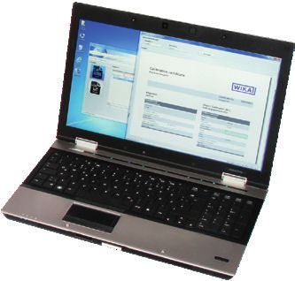
Easy and fast creation of a high-quality calibration certificate
The WIKA-Cal calibration software is used for generating
calibration certificates or logger protocols for pressure
measuring instruments and is available as a demo version for
a cost-free download.
A template helps the user and guides him through the
creation process of a document.
In order to switch from the demo version to a full version of
the respective template, a USB stick with the template has to
be purchased.
The pre-installed demo version automatically changes to
the selected full version when the USB stick is inserted and
is available as long as the USB stick is connected to the
computer.
■■ Creation of calibration certificates for mechanical and
electronic pressure measuring instruments
■■ Fully automatic calibration with pressure controllers
■■ Calibration of gauge pressure measuring instruments with
absolute pressure references and vice versa
■■ A calibration assistant guides you through the calibration
■■ Automatic generation of the calibration steps
■■ Generation of calibration certificates per DIN EN 10204
■■ Creation of logger protocols
■■ User-friendly interface
■■ Languages: German, English, Italian and more due with
software updates
For further information see data sheet CT 95.10
Calibration certificates can be created with the Cal-Template and logger protocols can be created with the Log-Template.
Cal Demo Calibration certificate Calibration certificate
Generation of calibration certificates limited to 2 measuring points, with
Kalibrierzeugnis Kalibrierzeugnis
Certificate No. 00000122 Certificate No. 00000122
Zeugnis-Nr. Zeugnis-Nr.
General Device under test (DUT) Measurement results
automatic initiation of pressures via a pressure controller.
Allgemein Kalibriergegenstand (KG) Messergebnisse
Calibration certificate Electrical gauge Reference value WS Reading DUT
Kalibrierschein Elektrisches Druckmessgerät Referenzwert GN Ablesung KG
bar bar
Customer Demo customer Model D-10
Kunde Demo street Typ ↑ ↓
DE-12345 Demo city Serial number demo1234 0.00000 0.0000 0.0010
Customer order No. Seriennummer 10.00000 10.0010 10.0020
Kundenbestellnummer Scale range (0 ... 10) bar g
Order date Anzeigebereich
Bestelldatum Accuracy 0.05 % FS
Date of calibration 01/02/2017 Genauigkeit
Datum der Kalibrierung Resolution (scale division) 0.0001 bar
Statement of compliance
Operator Demo User Auflösung (Skalenwert) Konformitätsaussage
Bearbeiter Measuring point No. demo tag
Messstellen-Nr Object keeps the specifications!
Der Kalibriergegenstand hält die Herstellerspezifikationen ein!
Environmental conditions Place of calibration
Umgebungsbedingungen Ort der Kalibrierung
Cal Light
Temperature (20,0 ± 0,1) °C Demo place g = (9.80946 ± 0.01) m/s²
Temperatur Musterort
Atmospheric pressure (1013,0 ± 0,1) hPa
Atmosphärischer Luftdruck
Rel. humidity (40 ± 1) %
Rel. Luftfeuchte
Measurement conditions
Generation of calibration certificates with no limitations on measuring
Messbedingungen
Working standard (WS) Pressure controller
Gebrauchsnormal (GN) Druckcontroller
Model Demo CPC
Typ
Calibration mark Demo 12345
Kalibrierzeichen
Scale range (0 ... 10) bar g
Anzeigebereich
points, without automatic initiation of pressures via a pressure controller.
Accuracy 0.02 % FS
Genauigkeit
Demo laboratory Tel.: 01234/56789 Demo laboratory Tel.: 01234/56789
Page 1/2 Page 2/2
Demo street 123 Fax: 01234/56789 Demo street 123 Fax: 01234/56789
Seite Seite
12345 Demo city E-Mail: demo@demo.com 12345 Demo city E-Mail: demo@demo.com
Demo country www.demo.com Demo country www.demo.com
Cal
Generation of calibration certificates with no limitations on measuring
points, with automatic initiation of pressures via a pressure controller.
Log Demo
Creation of data logger test reports, limited to 5 measured values.
Log
Creation of data logger test reports without limiting the measured values.
WIKA data sheet CT 27.40 ∙ 08/2019 Page 10 of 12Accessories for CPC4000 Order code
Description CPX-A-C4
19" rack mounting kit with side panels -R-
Barometric reference
Measuring range 552 ... 1.172 mbar abs. (8 ... 17 psi abs.) -6-
Accuracy to 0.02 % of reading
Measuring range 552 ... 1.172 mbar abs. (8 ... 17 psi abs.) -3-
Accuracy to 0.01 % of reading
Calibration adapter
for reference pressure sensors, voltage supply and software -4-
for barometric reference, voltage supply and software -5-
Transport case -7-
Adapter set
1/8" BSPG female thread (4 adapter) -B-
1/4" tube fitting (4 adapter) -I-
6 mm Swagelok® male thread (4 adapter) -M-
1/4" NPT female thread (4 adapter) -N-
1/8" NPT female thread (4 adapter) -S-
Block and bleed valve, ≤ 400 bar -8-
Coalescing filter ≤ 240 bar -9-
Automatic contamination protection, ≤ 210 bar -O-
Replacement filters for automatic CPS -2-
Ordering information for your enquiry:
1. Order code: CPX-A-C4 ⇓
2. Option: [ ]
WIKA data sheet CT 27.40 ∙ 08/2019 Page 11 of 12Scope of delivery
■■ Industrial pressure controller model CPC4000 (desktop
case)
■■ 1.5 m (5 ft) power cord
■■ Operating instructions
■■ A2LA calibration certificate (standard on factory)
Options
■■ DKD/DAkkS calibration certificate
■■ Second reference pressure sensor model CPR4000
■■ Barometric reference
■■ 19" rack-mounting kit
■■ Customer-specific system
■■ Adapters and fittings for pressure connections
■■ Automatic contamination prevention system (CPS)
Ordering information
Model / Case / Pressure range base instrument / Pressure unit / Pressure type / Minimum pressure range / Maximum pressure
range / Accuracy / Type of calibration certificate / Barometric reference / Type of certificate for barometric reference / Digital
interface / Pressure port adapters / Power cord / Additional ordering information
© 08/2015 WIKA Alexander Wiegand SE & Co. KG, all rights reserved.
The specifications given in this document represent the state of engineering at the time of publishing.
We reserve the right to make modifications to the specifications and materials.
WIKA data sheet CT 27.40 ∙ 08/2019 Page 12 of 12
08/2019 EN
WIKA Alexander Wiegand SE & Co. KG
Alexander-Wiegand-Straße 30
63911 Klingenberg/Germany
Tel. +49 9372 132-0
Fax +49 9372 132-406
info@wika.de
www.wika.deYou can also read