The Future is Now: 5G NR ATE and Field Test Systems Utilize Teledyne e2v's Quad ADCs to Revolutionize Auto-Calibrated Test Measurements.
←
→
Page content transcription
If your browser does not render page correctly, please read the page content below
WHITE PAPER         The Future is Now: 5G NR ATE and Field Test Systems
                    Utilize Teledyne e2v’s Quad ADCs to Revolutionize
                    Auto-Calibrated Test Measurements.                                                                         July 2020

              ABSTRACT

              As mobile wireless technology continues its rapid                    components, Teledyne e2v’s monolithic quad-channel,
              generational development over the last twenty years                  multi-port input ADCs utilizing unparalleled on-chip high
              from 3G to 4G, and now onto 5G NR networks, one                      frequency cross point switch input circuit technology,
              technological problem has been consistent throughout;                allows for auto-calibration and measurement techniques
              automatic/calibrated testing of required high frequency              in either RF ATE and/or Field-Testing environments.
              components.
                                                                                   Teledyne e2v’s EV12AQ605 and EV10AQ190 (12 and 10 bit
              The most difficult testing challenge for RF ATE and Field            quad-channel ADCs with cross point switch input circuit
              Test Systems is simply calibration, repeatability, and               technology) enable RF ATE and Field-Tester developments
              correlation of measured performance results in order to              to focus on auto-calibrated test measurements for both
              verify that they meet required specification limits. Now,            single channel and multi-port 5G NR devices.
              as the future of wireless technology transitions to 5G NR

              INTER-GENERATIONAL ISSUES

              5G is the telecommunication industry’s fifth generation              In 2018, an industry consortium setting standards for 5G (3rd
              technology standard for cellular networks, which began               Generation Partnership Project (3GPP)) defined any system
              worldwide deployment in 2019. 5G is the planned successor            using 5G NR (5G New Radio) software as 5G. 5G will ultimately
              to current 4G networks which provide connectivity to most            support an estimated 1M devices/km2 while 4G currently
              cellphones and will have greater bandwidth giving higher             supports approximately 100K devices/km2. Of course, 5G
              download speeds eventually up to 10 Gbit/s. Due to this              wireless devices will also have 4G LTE capability, due to the fact
              increased bandwidth, current 4G cellphones will not be able to       that the new 5G network will use existing 4G networks for initially
              use the new networks, which will require 5G enabled wireless         establishing the connections with the cell. The bottom line is
              devices. Conversely, 5G will also have to accommodate all 4G         future 5G components must not only cover the ever-expanding
              network requirements in regards to bandwidth, etc. Therefore,        performance demands of the 5G network requirements, but
              in order to ensure wide service, 5G networks will operate within     they must also cover previous generations: 2G/3G/4G/5G
              three frequency bands: low, medium, and high.                        (GSM/EDGE/CDMA/UMTS/WCDMA/LTE/LTE-A/TD-SCDMA/
                                                                                   TD-LTE, etc.).
              Low-band 5G (also called sub-1 GHz) uses a similar frequency
              range as 4G (600 -700 MHz) which yields download speeds              Therefore, future 5G NR ATE systems will need the ability to test
              slightly higher than 4G (30-250 Mbit/s).                             components over a broad range of frequencies in a reliable,
                                                                                   repeatable way that can be auto-calibrated and measured in order
              The medium-band 5G (also called sub-6 GHz) frequency range           to ensure results that correlate while also reducing test errors.
              is 2.5-3.7 GHz (download speeds of 100-900 Mbit/s). This level
              of service should be available in most metropolitan areas in 2020.   THE TROUBLE WITH ERRORS

              High-band 5G (also called millimeter-wave or mmWave)                 Characterizing the multitude of uncertainties/errors external to
              currently uses frequencies of 26, 28 or 39 GHz. The                  the DUT (Device Under Test) within an RF ATE measurement
              aforementioned 5G frequency bands have been tested in 2020,          environment, requires test configurations that will increase
              and new frequency medium bands (sub-6 GHz) are expected              confidence in taking measurements that ensure accurate and
              to be implemented in the upcoming months and years (i.e.             reliable characterization of the DUT/product performance.
              currently there are more than fifty 5G NR medium band                Characterizing and quantifying measurement uncertainty is
              frequencies in use worldwide).                                       critical in order to achieve desired results.

              FOR MORE INFORMATION: https://www.teledyne-e2v.com/products/semiconductors/adc/                                                 Page 1
WHITE PAPER         The Future is Now: 5G NR ATE and Field Test Systems
                    Utilize Teledyne e2v’s Quad ADCs to Revolutionize
                    Auto-Calibrated Test Measurements.                                                                            July 2020

              Generally speaking, the accuracy of a measured result is always       TIME FOR INDIVIDUAL COMPONENT                             AUTO-
              questionable simply because all measurements are influenced           CALIBRATION AND TEST MEASUREMENT
              by physical and electrical environment(s) and are limited by the
              capability of the source/measuring device/instrument(s) used.         Creating a reference plane for each DIB (Device Interface
              Therefore, the measured value is never exactly equal to the true      Board)/DUT within an RF ATE environment, requires defining
              value of the DUT/performance being tested. The difference             a calibration process (Figures 1a & 1b). Typically, standard(s) are
              between the measured and true performance value is simply             used for calibration. Ideally, standard(s) utilize a “gold reference
              called error. Depending on how errors originate (external to the      unit” DIB/DUT that would have less than one half to one quarter
              DUT), they can be broadly categorized as random or systematic         of the accumulated errors/measurement (Step1) compared
              errors. Random errors are just that, random. They are caused by       to a regular DIB/DUT measurement (Step 2). If this error is
              unpredictable temporal or spatial variations during test set-up       achieved (in Step 1), the accumulated measurements utilizing the
              and test measurement. Generally, random errors are extremely          standard(s) is considered to be sufficient when the actual DIB/
              difficult to trace or quantify in regards to how they affect the      DUT is tested (Step 2). Consistently maintaining minimum “gold
              DUT measurement result. Random errors mainly arise due                standard/reference unit” measurement errors within an RF ATE
              to changes in the RF ATE environment; such as temperature,            environment, over a wide range of frequencies, noise and voltage
              connectivity, instrument noise and distortion that also include       levels, and gains is very difficult, time consuming, and costly.
              repeatable errors in connections and cables.                          Of course, there are inter-connect and component variations

              Systematic errors are repeatable and can usually be resolved,
              but not entirely. Systematic errors can only be minimized to a
              certain degree. The concept of calibration is simply to estimate
              the systematic errors in a RF ATE test environment and correct for    Figure 1a. Simplified Block Diagram: Manual
                                                                                    Reference Plane Calibration Utilizing Gold
              them. Usually in order to successfully remove systematic errors,      Standard Reference Unit
              calibration standards or reference units are required. A standard
              or reference unit should represent or reproduce a known unit
              of measurements to a very high degree of accuracy. Calibration
              is then carried out by measuring/testing the standard/reference
              unit, with the measurement system, and that measurement               Figure 1b. Simplified Block Diagram: Auto-
              result is then stored as raw data. The raw data result is then        Measurement of DIB/DUT

              used to calculate the systematic errors that occurred during          that will significantly influence calibrating a reference plane
              the measurement by comparing the raw data measurement of              between the standard(s) and the DIB/DUT during calibration
              the standard/reference unit with their known values. This then        (i.e. including multiple Device Interface Board (DIB) anomalies,
              gives the error result. The systematic error result is then used to   DIB/DUT contacts/component variations, cables/connectors
              correct the measurement result. Unfortunately, for 5G NR ATE          impedances, source/measurement instrument variations, etc.)
              testers, including the DIB (Device Interface Boards, Probe Cards,     Bottom line, given all the above, is calibration methods for 5G
              Cables and Connectivity, etc.) over a variety of high frequencies     NR devices can involve a combination of manual testing that
              and test conditions, using standards/reference units, becomes         utilize standard(s) in order to establish a reference plane (which
              problematic. Another way to view calibration is to simply             introduce significant random errors) followed by auto-testing
              define a reference plane. A reference plane is accomplished by        which hopefully removes the systematic error sources.
              estimating the systematic errors in the test system environment
              and correcting for them. Unfortunately, random errors cannot          Figure 2 represents a generic 6-pin (surface mount package)
              be corrected within a reference plane environment. What is            5G NR Low Noise Amplifier (LNA) product/DUT (w/o external
              increasingly needed, within a RF/5G NR ATE and Field Test             components). This LNA example would need to be tested within
              Systems environment, is an ability to create a reference plane        an RF ATE environment that requires calibration prior to testing
              for each DUT utilizing automatic/calibration and measurement          in order to establish a reference plane. Typical RF ATE tests that
              techniques.                                                           would be required for an LNA include:

              FOR MORE INFORMATION: https://www.teledyne-e2v.com/products/semiconductors/adc/                                                   Page 2
WHITE PAPER          The Future is Now: 5G NR ATE and Field Test Systems
                     Utilize Teledyne e2v’s Quad ADCs to Revolutionize
                     Auto-Calibrated Test Measurements.                                                                                     July 2020

              • Operating Frequency Range (there are 50+ 5G NR network
                 frequency bands)
              • Gain/Insertion Loss
              • Gain Flatness (over frequency range(s))
              • Noise Figure
              • Input/Output Return Loss
              • Input IP3
              • Output IP3
                                                                                              Figure 3. Generic 6-Pin 5G NR LNA DUT/DIB with external components

                                                                                          So, what is needed for future 5G NR ATE systems, and testing field
                                                                                          installed telecom equipment, is the ability to test over a broad range
                                                                                          of frequencies, specifications, and conditions in a way that is reliable,
                                                                                          repeatable, and will correlate (given the previously mentioned errors).
                                                                                          It also needs to be auto-calibrated without introducing manual
                                                                                          calibration techniques that rely on standards in order to create a
                                                                                          reference plane. Figure 4 represents a simplified/conceptual block
                                                                                          diagram for an auto-calibrated 5G NR RF ATE measurement system
                                                                                          for any DIB/DUT (single or multi-port) irrespective of additional
                                                                                          required external components.
                    Figure 2. Generic 6-Pin 5G NR LNA DUT w/o external components

              Of course, besides testing this particular LNA device, an actual
              RF ATE environment also needs to have the capability to test
              other types of 5G NR type devices (Couplers, Attenuators, Filters,
              VGAs, etc., etc.). Tests may involve individual components, and/
              or at a sub-system level with multiple devices in cascade (i.e.
              Coupler + Attenuator + LNA + VGA + Filter, etc.). Therefore,
              multi-ports could also need to be tested as well.

              Figure 3 represents the same generic 6-pin (surface mount
              package) 5G NR Low Noise Amplifier (LNA) product/DUT
              with simplified/required external components necessary for
              operation. These components would be mounted to the DIB as
              close to the handler contacts as possible. Practically speaking,
              Figure 3 under high frequency stimulus, is significantly more                    Figure 4. Conceptual Block Diagram: Auto-Calibrated 5G NR RF ATE
                                                                                                                   Measurement/Test System
              complex than Figure 2 for both measurement and calibration.
              Anomalies between the DUT and the DIB/Handler include:
                                                                                          In order to make accurate, reliable and repeatable measurements
              • Attenuator mismatches and loss errors (required for impedance
                                                                                          within an RF ATE system, test engineers have to bridge the gap
                 matching and to scale DUT input/output levels)
                                                                                          between the high-quality connectors that are mounted on the
              • Variations of inductor performance(s) between the input and output
                                                                                          front panels of expensive rack-mounted source and receiver/
              • Changes in the interaction between the control line and gate driver
                                                                                          measurement instruments, and the real-world interface for
              • Ground loops
                                                                                          their DIB/DUT. The contact electrical interface to the DUT
              • Cable/Connection impedances
                                                                                          (whether a probe card or package/handler contact interface
              • Impedance differences in tightening the connectors to the test
                                                                                          card) is usually integrated within the DIB which is rarely fitted
                 system with every test module connection required
                                                                                          with the same type of high-quality connecters. The cascade
              As mentioned before, the calibration problems increase as the DUT
                                                                                          of multiple cables/connections between the source (to the
              size increases to multiple devices in the signal chain. As the variations
                                                                                          DUT) and receiver/measurement instruments (from the DUT),
              increase, calibration and auto-test errors exponentially increase.
                                                                                          including the DIB, will introduce substantial random and

              FOR MORE INFORMATION: https://www.teledyne-e2v.com/products/semiconductors/adc/                                                               Page 3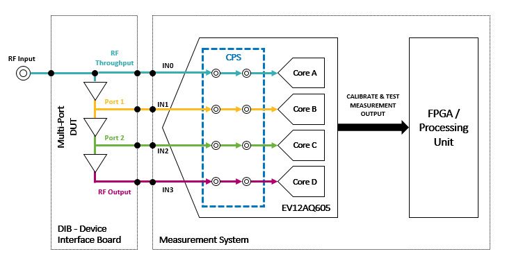
WHITE PAPER         The Future is Now: 5G NR ATE and Field Test Systems
                    Utilize Teledyne e2v’s Quad ADCs to Revolutionize
                    Auto-Calibrated Test Measurements.                                                                              July 2020

              systematic errors. In order to compensate for these errors, the    6 and 7) as well as multi-port 5G NR devices (shown in the next
              simplified RF ATE test configuration (Figure 4) allows for auto-   section). The CPS operates within 4 distinct modes (that can be
              calibration and measurement at the DUT ports without requiring     automatically enabled/controlled through the SPI):
              manual calibration techniques in order to establish a reference
              plane for each individual DIB/DUT. Figure 4 simply automates       • 1-ch mode IN0 input: Quad ADCs, interleaved, maximum
              the calibration/test measurement by directly measuring the            sample rate of 6.4 GSPS (4 X 1.6 GSPS)
              test configuration errors and correcting for them in the final     • 1-ch mode IN3 input: Same as above)
              DUT measurement (Raw Test Measurement – Calibration                • 2-ch mode IN0 input connected to both A & B ADCs; IN3
              Error Measurement = Final DUT measurement.) This can be               connected to both C & D ADCs with maximum sample rates
              accomplished by initially (automatically) switching the internal      of 3.2 GSPS (2 X 1.6 GSPS) for each channel
              cross point switch (CPS) to “Calibrate Error Measurement”          • 4-ch mode IN0-IN3 inputs individually connected to A, B, C,
              mode, and then allowing the ADC to make an RF Throughput              D, ADCs respectively; with maximum sample rates of 1.6 GSPS
              measurement inclusive of error contributors:                          for each separate channel
              • Direct RF Antennae/source noise and distortion
              • Input return loss/attenuator errors to the DUT                   Also, with an extended input bandwidth above 6 GHz (EFPBW),
              • Power supply issues                                              the EV12AQ605 allows the sampling of signals directly in the
              • Ground issues                                                    C-band (4-8 GHz) without the need to translate the signal
              • Ancillary source/driver issues (such as the example control     to baseband through a down conversion stage (Direct RF
                 port above)                                                     Sampling).
              • Connector and Cable errors/variations
                                                                                 Figure 5 depicts the simplified block diagram for taking an auto-
              This measurement is stored as the Calibration Error                calibrated measurement. The CPS is set to 1-ch (IN0 input)
              Measurement. The CPS is then automatically switched to             mode with the ADCs (A, B, C, D) measuring the RF Throughput
              “Raw Test Measurement” mode, the ADC makes the same                port of the DIB/DUT with the DIB/DUT RF Output disconnected
              measurement inclusive of the DUT (with required external           (by the CPS). This “Calibration Error Measurement” samples the
              components), and this data is stored as the Raw Test               combined errors of the DIB/DUT(Input):
              Measurement. The resulting data from the two measurements          • Direct RF Antennae/source noise and distortion
              are conditioned in software in order to produce an auto-           • Input return loss/attenuator/filter errors to the DUT
              calibrated/corrected final test measurement result. The internal   • Power and Ground Issues
              CPS enables the RF ATE engineer to automatically reconfigure a     • Input/Return Loss/Contact Issues from the DUT
              DIB/DUT, through a battery of tests, without the requirement of    •Ancillary source/driver/component issues contained on the
              manual intervention and recalibration. Of course, if the DIB/DUT     DIB that are required by the DUT
              consists of multiple devices in cascade, in the same manner as     • Connector and Cable errors/variations, etc.
              above, multi-ports can also be measured and auto-calibrated/
              corrected utilizing the quad ADC with the quad input cross point   This measurement from the ADCs is stored as the “Calibration
              switch (CPS) which will be explained later.                        Error Measurement”.

              5G NR ATE DUT AUTO-CALIBRATION AND TEST
              MEASUREMENT

              Figures 5 & 6 depict automated (2-state) solution(s) for a 5G NR
              ATE auto-calibrated and test measurement system which uses
              Teledyne e2v’s matched quad-channel, multi-port input ADCs
              utilizing unparalleled on-chip high frequency cross point switch
              (CPS). Teledyne e2v’s EV12AQ605 and EV10AQ190 (12 and 10
              bit quad-channel ADCs with cross point switch) enable 5G NR
              ATE and Field-Tester developments the ability to focus on auto-
                                                                                     Figure 5. Simplified Block Diagram: Auto-Calibrated Error Measurement
              calibrated test measurements for both single channel (Figures 5,

              FOR MORE INFORMATION: https://www.teledyne-e2v.com/products/semiconductors/adc/                                                         Page 4
WHITE PAPER The Future is Now: 5G NR ATE and Field Test Systems
Utilize Teledyne e2v’s Quad ADCs to Revolutionize
Auto-Calibrated Test Measurements. July 2020
5G NR ATE SYSTEMS/FIELD-TESTING OF INSTALLED
TELECOM EQUIPMENT
AUTO-CALIBRATION AND TEST MEASUREMENT
Figure 8 depicts the simplified block diagram for simultaneously
measuring multi-port DIB/DUT input/outputs in order to
auto-calibrate the measurement system including taking the
raw test measurement. The CPS is set to 4-ch mode where
each independent sampling ADC channel can operate at a
maximum sample rate of 1.6 GSPS. In this configuration, the
Figure 6. Simplified Block Diagram: Auto-Calibrated Raw Test Measurement
multi-port DIB/DUT can also be represented as required test/
Figure 6 depicts the simplified block diagram for taking a raw test measurement points for an installed field telecommunications
measurement. After the calibration error measurement is taken, system. In 4-ch mode ADCs (A, B, C, D) simultaneously
the CPS is then set to 1-ch (IN3 input) mode with ADC’s (A, B, C, measures the RF Throughput port, Port 1, Port 2, and the RF
D) measuring the RF Output port of the DIB/DUT with the DIB/ Output port of the DIB/DUT or Field Test System. Again, this
DUT RF Throughput port disconnected (by the CPS). This “Raw configuration simultaneously measures each port and the data
Test Measurement” samples the combined performance/errors can be utilized as either “Calibration Error Measurement” and/or
of the DIB/DUT(Input)/DUT(Output) such as: “Raw Test Measurement” performance. Final test measurement
• The same errors (previously mentioned in the Calibration Error calculations are then accomplished by subtracting any ports
Measurement) calibration errors from any raw test measurements.
• Plus, the DUT RF Output performance
This measurement from the ADCs is stored as the “Raw Test
Measurement.” The final DUT measurement is then calculated
by taking the Raw Test Measurement – Calibration Error
Measurement = Final DUT measurement.
Figure 7 depicts the simplified block diagram for taking both
a calibration error measurement and raw test measurement
simultaneously. The CPS is set to 2-ch mode (IN0 input
connected to both A & B and IN3 input connected to both C & Figure 8. Simplified Block Diagram: Simultaneous Multi-Port Auto-Calibrated
D ADCs). In 2-ch mode ADCs (A, B) measure the RF Throughput Error Measurement(s) and Raw Test Measurement
port of the DIB/DUT with the DIB/DUT RF Output also being
measured by ADCs (C, D). This configuration of simultaneously In addition, the EV12AQ605 includes a “multiple ADC chained
measuring the “Calibration Error Measurement” and the “Raw synchronization feature” which adds to the design flexibility
Test Measurement” is accomplished utilizing a maximum sample of these multi-port test measurements. The ADC chained
rate of 3.2 GSPS. Again, the final DUT measurement is then synchronization feature of the 4 ADC cores (clock tree and
calculated by taking the Raw Test Measurement – Calibration digital reset) enables automatic/multiple ADC time/phase
Error Measurement = Final DUT measurement. sampling adjustments and re-alignment techniques that allow
for measurement corrections in real-time. This ADC chained
synchronization feature also enables the system to be scaled
beyond 4-channels to potential 8, 12, 16, etc., channel multi-
system implementations.
UNIQUE QUAD ADCS W/CPS (EV12AQ605 &
EV10AQ190) ENABLE AUTO-CALIBRATION AND TEST
MEASUREMENT FOR 5G NR ATE SYSTEMS AND FIELD
TESTING OF TELECOM EQUIPMENT
Figure 7. Simplified Block Diagram: Simultaneous Auto-Calibrated Error Specifically, the EV12AQ605 is a quad channel 12-bit 1.6 GSPS
Measurement and Raw Test Measurements
FOR MORE INFORMATION: https://www.teledyne-e2v.com/products/semiconductors/adc/ Page 5WHITE PAPER The Future is Now: 5G NR ATE and Field Test Systems
Utilize Teledyne e2v’s Quad ADCs to Revolutionize
Auto-Calibrated Test Measurements. July 2020
ADC. The built-in Cross Point Switch (CPS) allows multi-mode
operation with the capability to interleave the four independent
cores in order to reach higher sampling rates. In 4-channel
operating mode, the four cores can sample, in phase, four
independent inputs at 1.6 GSPS. In 2-channel operating mode,
the cores are interleaved by 2 in order to reach 3.2 GSPS sampling
rate on each of the two inputs. In 1-channel operating mode, a
single input is propagated to each of the four cores which are
interleaved by 4 in order to reach a sampling rate of 6.4 GSPS.
This high flexibility enables digitization of RF (and IF) signals with
up to 3.2 GHz of instantaneous bandwidth. With an extended
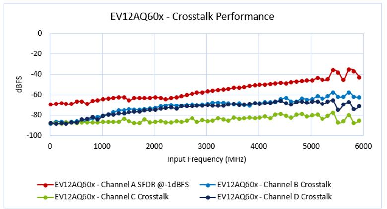
input bandwidth above 6 GHz (EFPBW) the EV12AQ605 allows Figure 10: EV12AQ605 crosstalk performance
the sampling of signals directly in the C-band (4-8 GHz) without
the need to translate the signal to baseband through a down- The EV10AQ190 is an earlier 10b version of a similar ADC with
conversion stage. The ADC includes a multiple ADC chained integrated cross point switch. An overview of both is shown in
synchronization feature to enable design of multi-channel the table below:
systems. The device is built in a non-hermetic flip-chip package
using HiTCE glass ceramic material in order to reach optimized
RF performance and higher pin density.
CONCLUSION
Figure 9: EV12AQ605 block diagram
As mobile wireless technology deploys 5G NR networks
An important performance point necessary to support the worldwide, automatic/calibrated high-speed testing of required
concept introduced in this paper is channel-to-channel isolation high frequency components is essential. With calibration,
or crosstalk. Large crosstalk would add additional error generated repeatability, and correlation of measured performance being
inside the ADC and skew the result. These could be corrected the utmost challenge for 5G NR ATE and Field Test Systems; these
within the auto-calibration process similarly to the other source issues also directly connect to overall test speed and throughput
of noise, however the state of the art crosstalk performance of in order to approach an ideal price performance ratio for test
the EV12AQ605 shown in Figure 10 proves that this additional developers. Teledyne e2v’s monolithic quad-channel, multi-port
noise would not be an issue when using this ADC. input ADCs utilizing unparalleled on-chip high frequency cross
point switch input circuit technology, enable auto-calibration
and measurement techniques for each component (single
or multi-port) tested in either 5G NR ATE and/or Field-Testing
environments.
FOR MORE INFORMATION: https://www.teledyne-e2v.com/products/semiconductors/adc/ Page 6For further information, please contact: For further information, please contact:
Marc Stackler, Yuki Chan,
Sales & Applications Engineer, APAC Marketing Communications Manager, APAC
Semiconductors Yuki.Chan@Teledyne.com
Marc.Stackler@Teledyne.com
www.teledyne-e2v.com/products/semiconductors/You can also read