Large Area Inspection Using 3D Point Cloud Data in a Disaster Response Robot
←
→
Page content transcription
If your browser does not render page correctly, please read the page content below
SHS Web of Conferences 102, 04010 (2021)                                                              https://doi.org/10.1051/shsconf/202110204010
ETLTC2021

      Large Area Inspection Using 3D Point Cloud Data in a Disaster Response
      Robot

      Hiroaki Ogawa1 , Keito Shishiki1 , Udaka A. Manawadu2 , and Keitaro Naruse1∗
      1
          Department of Computer Science and Engineering, University of Aizu, Aizu-Wakamatsu, Japan.
      2
          Graduate School of Computer Science and Engineering, University of Aizu, Aizu-Wakamatsu, Japan.

                    Abstract.
                    Large area inspection using a robot is critical in a disastrous situation; especially when humans are inhabiting
                    the catastrophic environment. Unlike natural environments, such environments lack details. Thus, creating
                    3D maps and identifying objects has became a challenge. This research suggests a 3D Point Cloud Data
                    (PCD) merging algorithm for the less textured environment, aiming World Robot Summit Standard Disaster
                    Robotics Challenge 2021 (WRS). Spider2020, a robotic system designed by the Robot Engineering Laboratory,
                    University of Aizu, was used in this research. Detecting QR codes in a wall and merging PCD, and generating a
                    wall map are the two main tasks in the competition. The Zxing library was used to detect and decode QR codes,
                    and the results were quite accurate. Since the 3D mapping environment has fewer textures, decoded QR code
                    locations are used as the PCD mapping markers. The position of the PCD file was taken from the location given
                    by the robotic arm in Spider2020. The accuracy of merging PCD was improved by including the position of
                    PCD files in the merging algorithm. The robotic system can be used for Large area Inspections in a disastrous
                    situation.

      1 Introduction                                                          spaces, then generate a map of targets quickly and accu-
                                                                              rately. QR codes gave the targets/ markers. By detecting
      Disaster response robots were among the most valuable                   the positions of the QR codes accurately, a complete 3D
      robots during the past few decades due to notable disas-                map should be generated. According to the outline of rules
      ters that humans faced. When it comes to human-made                     provided by WRS, the following instructions were given
      disasters, it is too dangerous for humans to reach the dis-             [4].
      aster environment. In nuclear disaster incidents such as
      Chernobyl and Fukushima Daiichi, it was too risky for                      1. Scanning should be started from the white box (see
      humans to enter the buildings to inspect the damages be-                      figure 1).
      cause radioactive materials were being released [1]. For                   2. As in figure 1 robot should investigate the wall area
      these kinds of emergencies, it is necessary to use large                      and create a large map of the QR codes within the
      area inspections remotely. A mobile rescue robot called                       targets.
      Quince was used for surveillance missions at Fukushima
      Daiichi nuclear power plant [2]. To inspect the inside of the              3. The submitted map’s quality and accuracy will be
      Fukushima Daiichi power plant, the research team consid-                      thoroughly considered for the competition’s final
      ered several requirements from the robots that have been                      points.
      used. They considered mounting sensors and cameras for
      3D mapping, which was identified as an excellent tool for                   As in figure 1 the width of the QR code may vary from
      understanding the disaster environment [1].                             140 mm to 7 mm, and the mapping coordinates of the start
                                                                              zone should be (x, y, z) = (0, 0, 0). Recognizing QR codes
          For addressing the issue of building a fully-equipped
                                                                              correctly and generating a map of the given wall with QR
      disaster response robot, World Robot Summit (WRS) in-
                                                                              codes accurately are the basic facts that are checked in the
      troduced a task under Standard Disaster Robot Challenge.
                                                                              competition.
      Those tasks were designed for assessing standard perfor-
                                                                                  As remote sensing technologies have rapidly devel-
      mance levels (e.g. mobility, sensing, information collec-
                                                                              oped in the last few years, 3D Point Cloud Data (PCD)
      tion, wireless communication, remote control, on-site de-
                                                                              is used to analyze textures in a wide area of fields [5].
      ployment and, durability) required in disaster prevention
                                                                              PCD files can be used for creating large 3D maps. Rusu
      and responses of robots [3]. Large area inspection (Code
                                                                              et al. have researched 3D Point cloud-based object maps
      name: Task EXP1) was designed to inspect a large area and
                                                                              for household environments [6]. They have mainly focused
      recognize targets that spread widely over flat and curved
                                                                              on large item detection, including cupboards, tables, draw-
           ∗ e-mail: naruse@u-aizu.ac.jp                                      ers, and shelves, which are of particular importance for a

© The Authors, published by EDP Sciences. This is an open access article distributed under the terms of the Creative Commons Attribution License 4.0
(http://creativecommons.org/licenses/by/4.0/).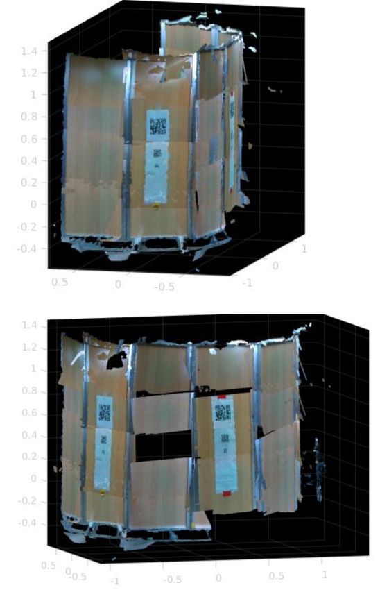
SHS Web of Conferences 102, 04010 (2021)                                                          https://doi.org/10.1051/shsconf/202110204010
ETLTC2021

      Figure 1. A sample curved surface is given in the WRS compe-
      tition for mapping. Targets (QR codes) are placed at heights of
      less than 2.5m, over an area of approximately 4m² to 40m² [4].

      household robotic assistant. Point cloud 3D mapping is                Figure 2. Spider2020 system. The red base is Giraffe robot and
      famous for collecting 3D Data in urban areas and outside              the Giraffe base was modified to put an external arm, external
      environments since the objects are large and easy to dis-             cameras, and external box PC.
      tinguish [7, 8]. Merging PCD files using visual similari-
      ties was used in the above research since they can be eas-            which enables capturing PCD files of higher targets. Ki-
      ily distinguished. Unlike in a natural environment, there             nova SDK gives access to different parameters of the arm.
      are fewer textures in an artificial environment. So it has            Intel Realsence camera was attached to a stable position of
      become an enormous challenge to identify objects using                a JACO arm (Figure 2). Intel Realsence D435 was used as
      cameras inside such an environment, like inside a power               the depth camera for this research. D345 has a maximum
      plant or a factory.                                                   of 90 frames per second and that helped to easily identify
           According to previous researches, building an accurate           QR codes quickly [9]. Functionalities that Realsence SDK
      and detailed 3D map in a less textured was never achieved.            gives to the RGB-D cameras were used for capturing PCD
      If it is achieved, it would be easily identified the objects          files.
      in a less textured environment from a point cloud 3D map.
      A robot can automatically identify small buttons, levers,
      or valves using this kind of accurate 3D map, especially              2.2 Software Development
      inside a factory. This research was mainly focused on gen-
      erating an accurate 3D map in a less textured environment.            For the task EXP1 in the WRS challenge, QR decoding and
                                                                            its location estimation, merging the PCD files, and gener-
                                                                            ating an accurate map are needed. For achieving those two
      2 Methodology                                                         tasks, two software systems were developed. One was for
                                                                            QR decoding using Zxing and the other for PCD merging,
      The main objective of this research was to build an accurate
                                                                            using Realsence SDK, and JACO arm SDK.
      point cloud from a less-textured environment. Since WRS
      task EXP1 is focused on the same goal, the research team
      mainly focused on the instructions and the guidelines given           2.2.1 QR Decoding Methodology
      by WRS when building the robot system. When selecting
      the hardware components, the research team primarily fo-              A library called Zxing was used for QR decoding. This
      cused on the ease of use, flexibility, equipment with a good          library is said to be more tolerant of poor environments
      Software Development Kit (SDK), and the hardware’s size.              than other QR libraries. Zxing is very popular and also
                                                                            used in Android’s Barcode Scanner app [10]. The lighting
      2.1 Spider2020 Robotic System                                         of the competition environment cannot be guaranteed, so
                                                                            this QR library was chosen to prepare for the worst-case
      A robotic system called "Spider2020" designed by REL                  scenario. The algorithm used for Zxing first binarizes the
      was used as the hardware interface (Figure 2). Spider2020             image and emphasizes the black and white, then detects
      is made by combining several hardware components such                 QR from the finder pattern embedded in the three corners.
      as a robotic crawler, a robotic arm, several cameras, and             Finally, the decoding area is checked, and the QR code is
      an integrated system. The base of Spider2020 is a disas-              decoded (As in figure 3).
      ter response robot called "Giraffe", a crawler-type robot                  The ratio of white cells to black cells is always 1: 1: 3:
      with two main crawlers and four sub crawlers. It also con-            1: 1 from any position of A, B, and C (refer figure 3), and
      sists of a KINOVA JACO arm with 6 degrees of freedom                  even if the image is rotated, it is possible to detect the po-
      curved wrist. The arm has a maximum height of 90 cm,                  sition and recognize the rotation angle from the positional

                                                                        2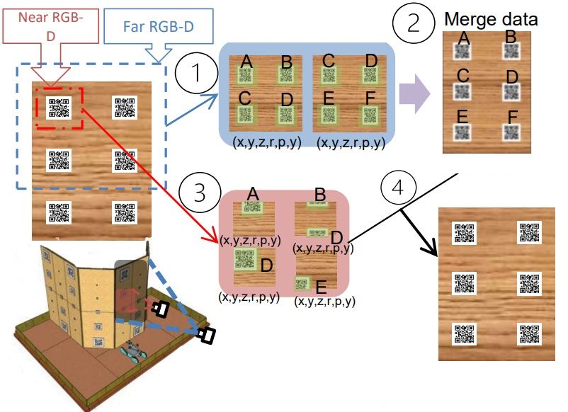
SHS Web of Conferences 102, 04010 (2021) https://doi.org/10.1051/shsconf/202110204010
ETLTC2021
and roll, pitch, yaw angles of the hand’s near tip (position
of end-effector) [12]. When capturing a PCD file position
of the robot hand and the robot hand’s rotation matrix, it
was saved in a text file alongside the PCD file. Since the
camera is aligned with the robot hand’s tip, those coordi-
nates were used as the camera position when taking the
Figure 3. ZXing’s QR finder pattern. PCD file. Some calculations should be done to convert
the robot arm position to camera positions. A Two-Stage
Frame Transformation was used to transfer PCD files in
relationship. This is the factor that makes QR Codes resis-
the camera frame to the base frame and merge them in the
tant to rotation [11].
base frame.
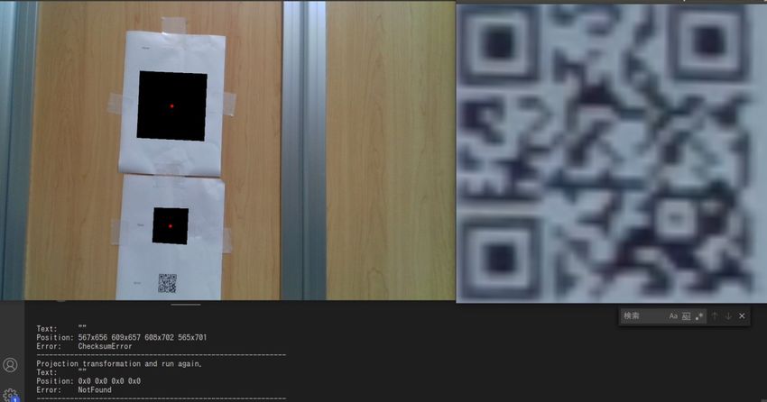
To decode multiple images from a single photo, the de-
coded QR is masked with a black area. In this way, the
decoding process can be performed efficiently. If a QR
code can be detected but cannot be decoded, the noise is
removed from the QR detection pattern position, and the
trapezoid is corrected and decoded again. This method
successfully expands QR decoding’s width (As in figure
4).
Figure 5. Camera frame to base frame transformation. x7 −y7 −z7
of the camera frame, first transformed to x6 − y6 − z6 to the hand
frame then x0 − y0 − z0 base frame
As in figure 2, Intel Realsence D435 is fixed to the
JACO arm. So, the frame transformation from camera
frame to hand frame is a fixed transformation (figure 5).
The relationship between x7 − y7 − z7 and x6 − y6 − z6
is given from the following matrix T 67 (Equation 1). 0m,
Figure 4. Expanded functions of QR decoding. Left is the whole 0.055m and -0.065m are the differences between x, y and
image, and right is the QR after noise removal and trapezoidal z values in camera and hand position.
correction. Below is the console screen at the time of execution.
−1 0 0 0
For the position estimation and to find the real-world
0 −1 0 0.055
coordinates of the QR code, finding the center point and
T 67 = (1)
projecting its coordinates onto the points obtained from the 0 0 −1 −0.065
Realsense is needed. For the given coordinates, the amount 0 0 0 1
of movement of the JACO arm is applied. By applying it to
all QRs, their positioning can be ascertained, and the better Frame transformation from hand frame to base frame
its accuracy, the better it will be evaluated in the competi- can be done from the hand position and orientation given
tion. by JACO SDK. It can be given by the matrix T 06 (Equation
2).
2.2.2 Capturing and Merging PCD Files. 0
1 0 x6
0 0 1 y6
After a QR code is decoded, it is required to take a PCD T 06 = (2)
1 0 0 z6
file of the QR code location. After taking all the PCD files,
0 0 0 1
two major problems arose when creating the 3D map of the
wall. x0 − y0 − z0 can be given from the following equation.
1. Accurate location of the PCD file was hard to
x0 x7
achieve only from the QR code. y
0
y7
z0 = T 06 T 67 (3)
2. Generate an Accurate 3D map needs more markers. z7
Since the environment was less textured and only 1 1
markers were QR codes, the accuracy of the final
map would be a problem. From x0 − y0 − z0 the accurate location of the PCD files
were taken. With the accurate locations merging PCD files
To address the first problem, the research team used JACO would be easy. Not all PCD files can be taken horizon-
arm SDK to get an accurate arm position other than the QR tally, they are tilted in various directions. There are roll,
code. Using JACO SDK, it is possible to get x, y, z-axis pitch, and yaw in the coordinate data of the arm, and affine
3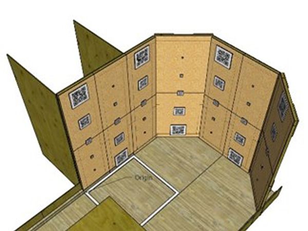
SHS Web of Conferences 102, 04010 (2021) https://doi.org/10.1051/shsconf/202110204010
ETLTC2021
transformation matrix was performed using those values to
straighten the tilted data [13]. Suppose affine transforma-
tion matrix is given by "A",
x
R y
A = (4)
z
0 0 0 1
A single rotation matrix can be formed by multiplying
the yaw, pitch, and roll rotation matrices to obtain a con-
version. Suppose roll, pitch, and yaw were given by α, β, γ.
R = Rz (α)Ry (β)R x (γ)
cos(β) cos(α) cos(α) sin(β) sin(γ) − cos(γ) sin(α) Figure 7. Hand position of JACO arm was converted in to the
base frame. x,y and z points of the each PCD files were repre-
= cos(β) sin(α) cos(γ) cos(α) + sin(β) sin(γ) sin(α)
sented as red, green and blue respectively.
− sin(β) cos(β) sin(γ)
cos(γ) cos(α) sin(β) + sin(γ) sin(α)
The images of the final 3D map is given in figure 8.
− cos(α) sin(γ) + cos(γ) sin(β) sin(α) (5)
Using PCD file positions as in figure 7, PCD merging was
cos(β) cos(γ)
successful and 3D maps can be constructed accurately. As
To address the second problem, shooting PCD files in picture below of figure 8, the places without QR codes
from far and near viewpoints was used [14]. The smaller need to be improved.
the number of data, the more accurate the merging of PCD
can be. From the distance viewpoint the details were un-
clear, But from the near viewpoints the details were clear
and less noisy. Figure 6 summarizes the methodology that
was used to capture and merge PCD files.
Figure 6. Capturing far (point 1 in the picture) and merge them.
The merged PCD files only from far points are noisy (point 2).
Using near PCD files (point 3) the output 2 is fine-tuned. The
final output (point 4) was more accurate than the point 2 output.
Since the location and the proper rotation of the PCD
files are available the research team used Matlab to merge
3-D PCDs [15].
Figure 8. Generated 3D map from the taken 25 PCD files as in
figure 7.
3 Results
The system was tested in a robot demonstration held in
Fukushima Robot Test Field on November 7-8, 2020. The 4 Conclusion
QR code decoding algorithm that was used could identify
every QR code that was given in WRS 2018. Apart from For detecting and decoding QR codes, the results given
QR decoding, a 3D map was generated using the hand po- by the Zxing library were quite accurate. Since there are
sition as in figure 7. Twenty-five near and far PCD files fewer textures in the environment, merging only from vi-
were taken to create the 3D map. sual points is not enough. The accuracy of merging PCD
4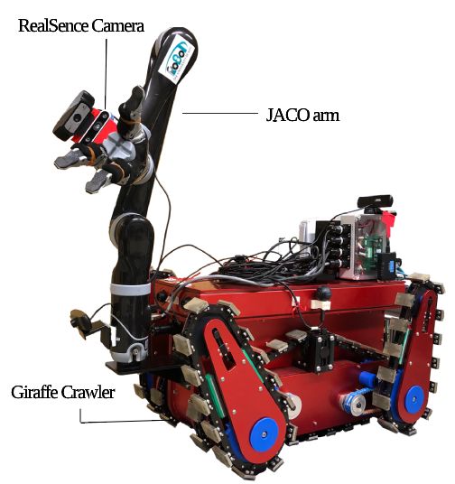
SHS Web of Conferences 102, 04010 (2021)                                                    https://doi.org/10.1051/shsconf/202110204010
ETLTC2021

      can be improved by including PCD files’ position into the        [6] R.B. Rusu, Z.C. Marton, N. Blodow, M. Dolha,
      merging algorithm. The final output can be improved if a             M. Beetz, Robotics and Autonomous Systems 56,
      higher number of PCD files are used for merging. As in               927 (2008)
      figure 8 the points with low accuracy can be improved by         [7] N. Haala, M. Peter, J. Kremer, G. Hunter, Int. Arch.
      taking more PCD files.                                               Photogramm. Remote Sens. Spat. Inf. Sci 37, 1119
                                                                           (2008)
                                                                       [8] Y. Xu, V. John, S. Mita, H. Tehrani, K. Ishimaru,
      References
                                                                           S. Nishino, 3D point cloud map based vehicle local-
       [1] K. Nagatani, S. Kiribayashi, Y. Okada, K. Otake,                ization using stereo camera, in 2017 IEEE Intelligent
           K. Yoshida, S. Tadokoro, T. Nishimura, T. Yoshida,              Vehicles Symposium (IV) (IEEE, 2017), pp. 487–492
           E. Koyanagi, M. Fukushima et al., Journal of Field          [9] Intel® realsense™ documentation, [online] .
           Robotics 30, 44 (2013)                                          available:,        https://dev.intelrealsense.com/docs/
       [2] K. Nagatani, S. Kiribayashi, Y. Okada, S. Tadokoro,             docs-get-started, accessed: 2020-04-03
           T. Nishimura, T. Yoshida, E. Koyanagi, Y. Hada,            [10] Zxing: A barcode image processing library [online] .
           Redesign of rescue mobile robot Quince, in 2011                 available:, https://opensource.google/projects/zxing,
           IEEE International Symposium on Safety, Security,               accessed: 2020-12-03
           and Rescue Robotics (IEEE, 2011), pp. 13–18                [11] Qr code configuration, [online] . available:,
       [3] T. Kimura, M. Okugawa, K. Oogane, Y. Ohtsubo,                   https://www.keyence.co.jp/ss/products/autoid/
           M. Shimizu, T. Takahashi, S. Tadokoro, Competi-                 codereader/basic2d_qr.jsp, accessed: 2020-12-03
           tion task development for response robot innovation        [12] Kinova™ ultra lightweight robotic arm, user guide
           in World Robot Summit, in 2017 IEEE International               [online] . available:, https://www.kinovarobotics.
           Symposium on Safety, Security and Rescue Robotics               com/, accessed: 2020-12-03
           (SSRR) (2017), pp. 129–130                                 [13] Affine transformation to fully understand [online] .
       [4] World      robot    summit,     standard    disaster            available:, https://qiita.com/, accessed: 2020-12-03
           robotics challenge.       [online]   .   available:,       [14] T. KONNO, The Journal of the Society for Art and
           https://worldrobotsummit.org/en/wrs2020/challenge/              Science 5, 80 (2006)
           disaster/standard.html, accessed: 2020-12-03               [15] Matlab      pcmerge,        [online]     .   available:,
       [5] M.E. Mohammadi, R.L. Wood, C.E. Wittich, IS-                    https://www.mathworks.com/help/vision/ref/
           PRS International Journal of Geo-Information 8, 527             pcmerge.html#bupmsru-1-ptCloudB,               accessed:
           (2019)                                                          2020-04-03

                                                                  5
You can also read