Directivity pattern of the sound radiated from square stepped-plate radiators
←
→
Page content transcription
If your browser does not render page correctly, please read the page content below
Acta Acustica 2020, 4, 11
Ó H. Xiping and L. Na, Published by EDP Sciences, 2020
https://doi.org/10.1051/aacus/2020010

                                                                                                                        Available online at:
                                                                                                         https://acta-acustica.edpsciences.org

 SCIENTIFIC ARTICLE

Directivity pattern of the sound radiated from square stepped-plate
radiators
He Xiping* and Li Na
Key Laboratory of Ultrasonics, Shaanxi Normal University, Xian, Shaanxi 710062, PR China

            Received 30 March 2020, Accepted 14 July 2020

            Abstract – A square flat-plate radiator driven by a longitudinal vibrator at the resonant frequency of its
            fourth-order natural vibration mode at its center for the generation of highly directional ultrasonic radiation
            in air is studied herein. The radiator was able to create a bending vibration mode whose four straight nodal
            lines were located at a 45° angle on each side. To obtain highly directional sound, the surrounding area of
            the four right isosceles triangles formed by a nodal line and two sides is modified to be raised one by half
            the wavelength of sound radiated in the propagation medium so that surface elements vibrate in phase. Then,
            the relation among the frequencies, nodal lines of the rhombus mode, and geometrical dimensions of the radi-
            ator is determined. The calculated directivity pattern of the stepped-plate radiator is equivalent to that of its
            corresponding theoretical piston, i.e., a stepped plate is a piston-like radiator. Results show that the measured
            vibrational-mode shape of the stepped-plate radiator is consistent with the calculated one, and the calculated
            directivity pattern is almost similar to the measured one.

            Keywords: Square stepped-plate radiator (SSPR), Flexural vibration, Response mode, Directivity pattern

1 Introduction                                                              precipitation, ultrasonic levitation, ultrasonic cohesion,
                                                                            ultrasonic debubbling, and other ultrasonic processing
    High-power ultrasonic transducers, commonly used for                    needs [14–20]. To suppress the bending motion of the radi-
gases, are aerodynamic systems of various types such as                     ation plate and set the transducer close together, Yamamori
whistles and sirens [1–6], in which the acoustic energy is                  et al. changed the radiating surface of a bolt-clamped
provided by a gas jet. However, the sounds they emit are                    Langevin-type transducer used in ultrasonic cleaning from
complex, the efficiencies are low, and the directivities are                 round to square [21].
poor in these devices. In practical applications such as                        A flexural vibration square-plate radiator with steps
detection of objects and measurement of distances the                       having in-phase vibration driven at its center by a longitu-
impedance mismatch in air coupling transducers between                      dinal vibration transducer is thoroughly studied herein.
the transducer surface and air is large, resulting in only a                A square flat plate driven by a longitudinal vibration trans-
small amount of energy transmission. Most of the energy                     ducer with the same resonant frequency at its center was
loss occurs during the transformation of energy from the                    able to create a flexural vibration mode whose four nodal
transducer to air.                                                          lines were located at a 45° angle on each side (no such a
    To obtain highly directional sound and good impedance                   mode in the natural modes of the square flat plate). To
matching to air or fluids and multiphase media, Gallego–                     obtain highly directional sound, the surrounding area of
Juárez et al. introduced a square stepped-plate, whose                      the four isosceles triangles formed by a nodal line and two
raised step height at coincident nodal lines with the edges                 sides was modified to be raised as a Square Stepped-Plate
is half the wavelength of the radiated sound. They also                     Radiator (SSPR) whose thickness increment was approxi-
developed several other types of airborne sonic and ultra-                  mately half the wavelength of the radiated sound in the
sonic power generators [7–10], which comprise a flexural                     propagation medium, enabling surface elements to vibrate
vibrating circular-plate radiator, or a rectangular plate                   in phase and avoiding phase cancellation (the profile of
radiator with a stepped profile, driven at its center by a                   the SSPR is shown in Fig. 4a).
piezoelectric vibrator. These are required for many applica-                    The calculated radiation pattern of the stepped radiator
tions such as for detecting or locating distant objects [11],               was better than that of the flat one, whose configuration
dehydration of food for preservation [12, 13], ultrasonic                   was similar to that of the theoretical piston. The measured
                                                                            vibrational-mode shape of the stepped-plate radiator was
*Corresponding author: hexiping@snnu.edu.cn                                 consistent with the calculated one. This type of SSPR
This is an Open Access article distributed under the terms of the Creative Commons Attribution License (https://creativecommons.org/licenses/by/4.0),
              which permits unrestricted use, distribution, and reproduction in any medium, provided the original work is properly cited.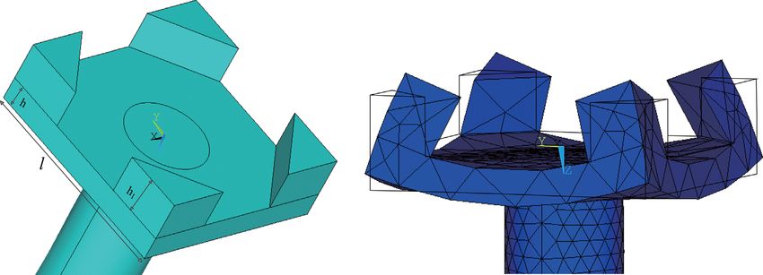
2                                      H. Xiping and L. Na: Acta Acustica 2020, 4, 11

oscillating in simpler bending mode is expected to be used
in ultrasound distance and level measurements in stock
owing to its extensive surface exhibiting good impedance
matching to air, its high directivity, and its high strength
and amplitude at its operating frequency when driven by
a longitudinal sandwiched vibrator.
                                                                    Figure 1. The finite element model of a square thin plate.

2 Theoretical calculations                                          transducer at the primary frequency. Adjusting the position
    A square thin plate with a free edge is shown in Figure 1.      and height of the step can compensate for the flexural vibra-
Waller tested the natural vibration modes of a square plate         tion and ensure that the edges of the step coincide with the
[22, 23] and found that the natural modes of a square plate         location of the nodal lines. After adjustment, the coordinates
are complex and irregular. Figure 2 shows 1st, 2nd, 3rd and         of nodes 1–8 were (0.025,0.009,0), (0.009,0.025,0), (0.009,
4th mode shapes of a Square Flat-Plate Radiator (SFPR).             0.025,0), (0.025,0.009,0), (0.025,0.009, 0), (0.009,
                                                                    0.025,0), (0.009,0.025,0), and (0.025,0.009,0), respec-
                                                                    tively. Here, the height of the step was h1 = c/2fe2 =
2.1 Response vibration mode                                         0.01 m, where c is the propagation velocity of sound waves
    The side length l of the SFPR was 50 mm and its thick-          in air (at 15 °C), as shown in Figure 4a. Figure 4b shows
ness h (it is also called thickness of the base plate) was          the response vibration mode at fe2 = 15,751 Hz.
6 mm. The material used was steel with a Poisson ratio
of m = 0.28, Young’s modulus of E = 1.96  1011 N/m2,               2.2 Directivity pattern
and a density of q = 7.91  103 kg/m3. The corresponding                Let us assume that the radiator is mounted flush with
frequency f of the profile of its fourth vibration mode, as          an infinite baffle, with the coordinate origin O taken as
shown in Figure 2d, was 19,332 Hz.                                  the center of the upper surface as shown in Figure 5. The
    Connection of the SFPR center by a bolt to a longitudi-         radiator driven by a longitudinal vibrator radiated waves
nal vibration transducer with the same resonant frequency           to the front half of the baffle space. Observation point
f = 19,332 Hz formed a compound vibration system. The               Q(x0,y0,z0) was located in the far field. The radiator was
commercial finite element program ANSYS was employed                 divided into multiple elements, each of which has an
to perform the computations. The 10-node quadratic                  infinitesimal area of ds = dxdy. According to the Rayleigh
element solid187 was used to model the radiators. The flat           integral formula, the radiation pressure at point Q gener-
radiator was divided into 449 elements. Through a harmonic          ated by the infinitesimal area ds can be expressed as follows
response analysis, the vibration mode shape of the radiator
with four straight nodal lines intersecting two adjacent sides                              kq0 c0
                                                                                    dp ¼ j              uðx; y ÞejðxtkRÞ ds;       ð1Þ
can be obtained at frequency fe1 = 19,006 Hz, as shown in                                     2pR
Figure 3a.                                                                   qffiffiffiffiffiffiffiffiffiffiffiffiffiffiffiffiffiffiffiffiffiffiffiffiffiffiffiffiffiffiffiffiffiffiffiffiffiffiffiffiffiffiffiffiffiffiffiffiffiffiffiffiffi
    The obtained mode is called the rhombus response mode                                     2                      2
                                                                    where R ¼ ðx0  xÞ þ ðy 0  y Þ þ z0 2 is the distance
that does not exist in the eigenmodes of the SFPR, i.e., it can
be created only if driven by a longitudinal vibrator. The coor-     between the infinitesimal area ds and the observation point
dinates of the eight nodes can be calculated from the vibra-        Q, and u(x, y) is the vibration velocity amplitude of the
tion displacement perpendicular to the square-plate plane           infinitesimal area ds.
along the four sides. The nodes are shown in Figure 3b.                 The radiation pressure generated from the whole radia-
The coordinates of node numbers 1–8 in units of meters were         tor can be expressed as follows
(0.025,0.004,0), (0.004,0.025,0), (0.004,0.025,0), (0.025,                                 ZZ
                                                                                      kq0 c0     uðx; y Þ jðxtkRÞ
0.004,0), (0.025,0.004,0), (0.004,0.025,0), (0.004,                          p¼j                     e         ds;     ð2Þ
0.025,0), and (0.025,0.004,0), respectively. The connec-                              2p          R
tions between nodes 1 and 2, 3 and 4, 5 and 6, and 7 and 8          R in the denominator can be approximately replaced with
were just the four nodal lines, and each line intersected two       r (the distance between the coordinate origin and the
sides of the plate with an angle of 45°, being an isosceles right   observation point Q) for r is much greater than the side
triangle.                                                           length of the SFPR. From Figure 5, R in the exponent
    The surface elements on two sides of a straight nodal           (i.e., the phase section) can be approximately expressed
line vibrated out of phase, leading to cancellation. The            by the following equation
SFPR (#I) can be improved as a stepped radiator (#II).
The raised step was added at the section surrounded by                                              x0 x þ y 0 y
                                                                                          R¼r                   :
the four isosceles triangles formed by one straight nodal line                                           r
and two adjacent sides, whose height was equal to the half
                                                                    Direction cosines at point Q are expressed as follows
the wavelength of the sound radiated in the propagation
medium. The original straight nodal lines will be expanded                               x0         y          z0
                                                                                cos a ¼ ; cos b ¼ 0 ; cos c ¼ ;
outside for the raised square stepped plate driven by the                                r           r          r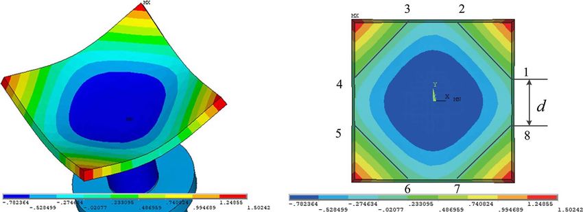
H. Xiping and L. Na: Acta Acustica 2020, 4, 11                                          3

                                        (a)                                         (b)

                                        (c)                                         (d)
Figure 2. The first four natural vibration mode shapes of an SFPR (a) 1st, (b) 2nd, (c) 3rd, and (d) 4th.

                                 (a)                                                      (b)
Figure 3. A response vibration mode obtained at 19,006 Hz by driving center of the SFPR with a longitudinal vibration transducer.
(a) The response vibration mode, (b) position of the four straight nodal lines.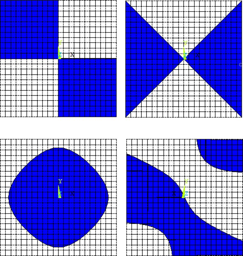
4                                         H. Xiping and L. Na: Acta Acustica 2020, 4, 11

                                  (a)                                                        (b)
Figure 4. A square stepped plate and its response vibration mode. (a) The stepped plate, (b) the vibration mode at fe2 = 15,751 Hz.

                              z              Q (x0, y0 , z0 )                X
                                                                             N
                                                                      B2 ¼         ui ðx; yÞðcosðkxi sin h cos /Þ sinðky i sin h sin /Þ
                                                                             i¼1
                                         r                                   þ cosðky i sin h sin /Þ sinðkxi sin h cos /ÞÞsi ;
                                              R
                                                                    where ui represents the vibration velocity of segment
                                  T                                 number i, and xi and yi represent the coordinates of seg-
                                                           y
                              o                                     ment number i. Therefore, the amplitude of radiation
                                  M                                 pressure is as follows
                                                                                                    qffiffiffiffiffiffiffiffiffiffiffiffiffiffiffiffi
                              ds= dxdy                                                        kq c0
                                                                                        jp j ¼ 0     B21 þ B22 :          ð4Þ
                                                                                               2pr
                          x
                                                                    According to the definition,
Figure 5. Calculation of the radiation pressure generated by
                                                                                                          jP jh
the square-plate radiator.                                                                   Dðh; /Þ ¼           :                    ð5Þ
                                                                                                         jP jh¼0
and the relations between the direction cosines and the             By combining with equation (4), the directivity formula can
sphere coordinates are shown below                                  be expressed as follows

             cos a ¼ sin h cos u; cos b ¼ sin h sin u:                                         pffiffiffiffiffiffiffiffiffiffiffiffiffiffiffiffiffiffiffi

                                                                                                B1 2 þ B2 2
Substituting the above equations into equation (2) yields
                                                                                     Dðh; /Þ ¼  N                  :      ð6Þ

the following equation                                                                          x P q s
                                                                                                         i      i
                      kq c0                                                                              i¼1
               p ¼ j 0 ejðxtkrÞ ðb1 þ jb2 Þ;                ð3Þ
                       2pr                                          The displacement n and vibration velocity v of the plate are
where                                                               related as follows
         ZZ
   b1 ¼      uðx; yÞðcosðkx sin h cos /Þ cosðky sin h sin /Þ                on oðqejxt Þ
                                                                       v¼      ¼         ¼ jxqejxt ¼ uejxt ;          so   u ¼ jxq:
                                                                            ot    ot
            sinðkx sin h cos /Þ sinðky sin h sin /ÞÞdxdy;
                                                                    The commercial finite element program ANSYS was
           ZZ                                                       employed to perform the computations. The vibration dis-
    b2 ¼         uðx; yÞðcosðkx sin h cos /Þ sinðky sin h sin /Þ    placements qi of each infinitesimal can be obtained by the
                                                                    finite element modal calculation. Then, extraction of the
           þ cosðky sin h sin /Þ sinðkx sin h cos /ÞÞdxdy:          displacements of each infinitesimal at the plate plane and
                                                                    their substitution into equation (6) allowed the radiation
Discretization of b1 and b2 provides the following equations        directivity patterns of the two radiators to be obtained
         XN                                                         through the programming calculation, as shown in Figure 9
  B1 ¼       ui ðx; yÞðcosðkxi sin h cos /Þ cosðky i sin h sin /Þ   in Section 3.2. There is one issue that needs to be illus-
           i¼1                                                      trated. The radiation surfaces were not on the same flat
          sinðkxi sin h cos /Þ sinðky i sin h sin /ÞÞsi ;         plane (the radiation surfaces on the steps were located at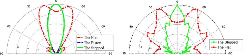
H. Xiping and L. Na: Acta Acustica 2020, 4, 11                                            5

a half wavelength above the flat plane) and the surface
elements still remained vibrating in the counter phase.
However, the radiation of the steps and the flat plane were
in phase. Therefore, considering the symbol of the displace-
ment on the flat plate as the opposite sign in counter-phase
zones (actually these zones were modified as steps) or con-
sidering all displacement values on the flat plate as absolute
ones. Displacement of the stepped-plate radiator can be
calculated using the displacement of the flat plate.

3 Experimental measurement of the response
  mode and directivity patterns
3.1 Response mode
                                                                 Figure 6. Fabricated square-plate radiators I and II.
    The flat and the stepped-plate steel radiators I and II
described above were fabricated (Figure 6). The II# SSPR
can be obtained by milling a thick square plate.                 response mode of the SFPR at ft1 = 18,563 Hz is shown in
    Radiators I and II were excited with sinusoidal signals      Figure 7a. It can be seen from Figures 3b to 7a that the
provided by the Polytec PSV-400 Scanning Vibrometer.             calculated response mode was similar to the tested one,
The laser sensor of the Polytec PSV-400 Scanning Vibrome-        the frequency error being D1 = |fe1  ft1|/ft1 = 2.3%.
teris scanned on the surface of the radiators (the stepped       The stepped-radiator II was modified from the flat-plate
surface faced the longitudinal vibrator and its flat back         radiator I. For radiator II, the nodal lines were extended
surface faced the laser sensor to be scanned for radiator II),   while adding the step to the surface of the original radiator
and the velocity spectra and the modes corresponding to          I. However, after adjustment, the nodal line positions were
the peak values can be obtained, as shown in Figures 7a          consistent with those of the measured step edges, and the
and 7b. Accordingly, the frequencies corresponding to the        frequency error was D2 = |fe2  ft2|/ft2 = 1.3%.
modes for radiators I and II were ft1 = 18,563 Hz and                The dashed–dot, dashed, and solid lines shown in
ft2 = 15,547 Hz, respectively.                                   Figure 9a show the calculated directivity patterns of the
                                                                 flat, theoretical piston, and square stepped radiators,
3.2 Directivity patterns                                         respectively. Here, a theoretical piston means all portions
                                                                 of the SFPR vibrated in phase with the same amplitude,
    The schematic of the experimental setup used to perform      whose side length was the same as that of the stepped plate.
the directivity measurements is shown in Figure 8. The plate     It can be seen from Figure 9a for the SSPR II that there
of the transducer was placed in a large flat foamed plastic       exist a sharper major lobe and some side lobes. However,
baffle. The acoustic pressure probe (a type uc-29 micro-          the side lobes are minor compared to the main lobe, demon-
phone 14 in. diameter, its working frequency ranged from         strating that the sound energy distribution was concen-
20 Hz to 100 kHz) was placed in the far field in front of         trated. The SSPR II exhibited good directionality. As
the plate. The frequency range of a type NA-42 sound level       expected, the calculated directivity pattern of a stepped-
measuring amplifier was from 1 Hz to 100 kHz. Both type           plate radiator is equivalent to that of its corresponding
uc-29 microphone and type NA-42 sound level measuring            theoretical piston, i.e., a stepped plate is a piston-like radi-
amplifier are manufactured by Rion Co., Ltd., Japan.              ator. However, for the SFPR I, there is no major lobe along
Measurements were obtained in an unobstructed environ-           its acoustic axis direction, demonstrating that the SFPR
ment, which was on the roof of our laboratory building. Each     has poor directionality.
test was performed across 90° for the transducer and                 Comparisons of Figures 9a and 9b show that the calcu-
mirrored to complete the plot, as shown in Figure 9. The         lated directivity patterns are almost similar to those of the
dotted and solid lines represent the directivity patterns of     measured ones. However, there are certain differences
the square flat and stepped radiators I and II, respectively.     between the measured directivity patterns and the calcu-
                                                                 lated ones. For example, the major lobes of the former are
                                                                 wider than those of the latter. The first reason for this
4 Analysis and discussion                                        difference is that the actual area of the flat foamed plastic
4.1 Calculation and measurement                                  baffle mounted in the experiment was finite rather than infi-
                                                                 nite, i.e., radiation from the back of the radiators may affect
    The calculated frequency of the fourth-order natural         the acoustic field in front of the radiators. The second rea-
vibration of the SFPR I was f = 19,332 Hz, and the response      son is that the diffraction field, which was generated by the
mode, as shown in Figure 3b, did not exist in its eigenmodes.    unbaffled upper surface at the outer edge by the pressure
It could be only obtained while exciting the SFPR with the       from the surface underneath, may affect the acoustic field
same longitudinal vibration frequency, which corresponded        [24]. The third reason for this difference is that the standard
to the calculated frequency of fe1 = 19,006 Hz. The tested       values of the plate material parameters were different from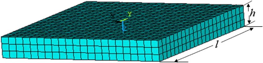
6                                     H. Xiping and L. Na: Acta Acustica 2020, 4, 11

Figure 7. The vibration velocity spectra and the modes at the peak values of two radiators. (a) Radiator I, (b) Radiator II.

those of the practical values of the material. Finally, manu-      the relation among the frequency, nodal lines of the rhom-
facturing errors and misalignment during the assembly              bus mode, and geometrical dimensions of the radiator, the-
process may also contribute to this discrepancy.                   oretical calculations were conducted and the results are
                                                                   listed in Table 1. From the table, one can see that, with
4.2 Relation among the frequency, nodal lines                      increasing side length of the radiator, the frequency of the
    of the rhombus mode, and geometrical                           fourth-order natural mode decreased when the thickness
    dimensions of the SFPR                                         of the plate was held constant; the frequency fe1 correspond-
                                                                   ing to the rhombus response mode decreased if driven at its
   The material used for the SFPR was steel. The thick-            center by a longitudinal vibrator at the frequency f of the
ness h of the plate radiator was 6 mm. To further illustrate       fourth-order natural mode, and the distance between the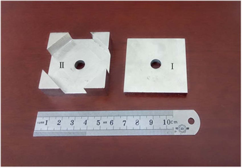
H. Xiping and L. Na: Acta Acustica 2020, 4, 11                                           7

                              Transducer
                                                                               Microphone

                                        +

                         Digital power                      B affle
                                             Tune table
                            meter

                                                                                                   NA- 42 Sound
                           Ultrasonic                                                             Level Measuring
                           generator                                                                 Amplifier

Figure 8. Experimental setup for the measurement of directivity pattern.

                                  (a)                                                       (b)
Figure 9. The directivity patterns of the square plate radiators. (a) The calculated, (b) the measured.

Table 1. Relation among the frequency, nodal lines of the rhombus response mode, and geometrical dimensions of the SFPR.

l (mm)            60            65             70          75             80           85               90           95     100
f (kHz)          13.80        11.86          10.29         9.02           8.00         7.07             6.33         5.70   5.16
fe1 (kHz)        12.97        11.11          9.60          8.41           7.39         6.51             5.86         5.28   4.76
d (mm)           10.08        10.60          10.92        11.70          12.12        12.60            13.30        13.68   14.40

Table 2. Relation between the rhombus mode and the thickness of plate.

h (mm)             6           6.5             7           7.5             8           8.5               9           9.5     10
f (kHz)          19.32        20.66          21.95        23.19          24.39        25.51            26.59        27.34   28.51
fe1 (kHz)        18.36        19.44          20.62        22.22          22.80        23.65            24.54        25.32   26.25
d (mm)           4.10         3.80           3.50          2.50           3.30         3.10             3.00         2.00   1.50

first and eighth nodes (as shown in Fig. 3b) increased, i.e.,          Fig. 3b) decreased, i.e., the nodal lines shrank inside, as
the nodal lines expanded outside.                                     shown in Table 2.
    By keeping the side length (l = 50 mm) of the radiator
constant, the frequency of the fourth-order natural mode
increased with increasing thickness of the plate h, the fre-          5 Conclusions
quency fe1 corresponding to the rhombus response mode
increased if driven at its center by a longitudinal vibrator             In this paper, an SSPR was introduced to improve an
at frequency f of the fourth-order natural mode, and the dis-         SFPR, and the response vibration mode and the directivity
tance d between the first and eighth nodes (as shown in                pattern were calculated. The calculated and test results
8 H. Xiping and L. Na: Acta Acustica 2020, 4, 11
were basically consistent. To sum up the results obtained ultrasonic radiation. Journal of the Acoustical Society of
herein, the following conclusions can be drawn. America 51 (1972) 953–959.
8. J.L. San Emeterio, J.A. Gallego-Juárez, G. Rodriguez-Corral:
High axisymmetric modes of vibration of stepped circular
1. If the SFPR was driven at its center by a longitudinal
plates. Journal of Sound and Vibration 114 (1987) 495–505.
vibrator with the same resonant frequency as its 9. J.A. Gallego-Juárez, G. Rodriguez, V. Acosta, E. Riera:
fourth-order natural one, a new rhombus response Power ultrasonic transducers with extensive radiators for
mode appeared that did not exist in the eigenmodes industrial processing. Ultrasonics Sonochemistry 17 (2010)
of the SFPR whose four straight nodal lines were 953–964.
located at a 45° angle on each side. 10. J.A. Gallego-Juárez, G. Rodriguez, S.E. Riera, F.V. Martinez,
2. The SSPR can serve as an improved form over the C.C. Pozuelo, V.M. Acosta: Recent developments in vibrat-
flat-plate radiator through calculation of the position ing-plate macrosonic transducers. Ultrasonics 40 (2002) 889–
of the straight nodal lines of the rhombus response 893.
mode. Its mechanical process was simple, and its beam 11. J.A. Gallego-Juárez, G. Rodriguez, J.L. San Emeterio, P.T.
Sanz, J. C. Lázaro: An acoustic transducer system for long-
pattern configuration of sound radiation was highly
distance ranging applications in air. Sensors and Actuators
directional, which was equivalent to that of a theoret- A: Physical 37–38 (1993) 397–402.
ical piston with the same size of the square piston 12. S.F. Blanco, S.E. Riera, V.M. Acosta, A.B. Blanco, J.A.
plate radiator. Gallego-Juárez: Food drying process by power ultrasound.
3. The flexural resonant frequency of the SSPR could be Ultrasonics 44 (2006) e523–e527.
applied to long-distance range and level measurement 13. J.A. Gallego, G. Rodriguez, J.C. Gálvez, T.S. Yang: A new
in stock. Similarly, the larger size of the square high-intensity ultrasonic technology for food dehydration.
stepped radiator was also highly directional, and it Drying Technology 17 (1999) 597–608.
can be used in various applications such as ultrasonic 14. Y. Zheng, Q.K. Zhang: Simultaneous measurement of gas and
cleaning, ultrasonic defoaming, and ultrasonic drying. solid holdups in multiphase systems using ultrasonic tech-
nique. Chemical Engineering Science 59 (2004) 3505–3514.
15. P. Collas, M. Barmatz, C. Shipley: Acoustic levitation in the
presence of gravity. Journal of the Acoustical Society of
Conflict of interest America 86 (1989) 777–787.
16. D.P. Gautam, L.F. Donald: Acoustically aided separation of
Author declared no conflict of interests. oil droplets from aqueous emulsions. Chemical Engineering
Science 59 (2004) 3183–3193.
17. J.A. Gallego-Juárez, G. Rodriguez-Corral, L. Gaete-Garreton:
Acknowledgments An ultrasonic transducer for high power applications in gases.
Ultrasonics 16 (1978) 267–271.
This work was supported by the National Natural 18. I. Gonzalez, J. Rodríguez, I. Garmendia, J.A. Gallego-Juárez:
Application of high intensity air-borne ultrasound for debub-
Science Foundation of P. R. China (Grant No. 11774211). bling liquid coating layers. Ultrasonics 44 (2006) e529–e532.
19. E. Riera, J.A. Gallego, T.J. Mason: Airborne ultrasound for
the precipitation of smokes and powders and the destruction
References of foams. Ultrasonics Sonochemistry 13 (2006) 107–116.
20. G. Rodriguez, E. Riera, J.A. Gallego, V.M. Acosta, A. Pinto,
1. B. Vonnegut: A Vortex whistle. Journal of the Acoustical I. Martinez, A. Blanco: Experimental study of defoaming by
Society of America 26 (1954) 18–20. air-borne power ultrasonic technology. Physics Procedia 3
2. C. Robert: Chanaud: Experiments concerning the Vortex (2010) 135–139.
Whistle. Journal of the Acoustical Society of America 35 21. H. Yamamori, T. Ito, K. Ohya, H. Banno: Characteristics of
(1963) 953–960. bolt-Clamped Langevin type ultrasonic transducer with
3. I. Michelson: Theory of Vortex Whistle. Journal of the square radiating surface. Journal of the Physical Society of
Acoustical Society of America 27 (1955) 930–931. Japan 29 (1990) 167–169.
4. S. Narayanan, P. Bhave, K. Srinivasan, K. Ramamurthi, 22. M.D. Waller: Vibrations of free square plates: part I. Normal
T. Sundararajan: Spectra and directivity of a Hartmann vibrating modes. Proceedings of the Physical Society 51
whistle. Journal of Sound and Vibration 321 (2009) 875–892. (1939) 831–844.
5. P. Greguss: The applications of air-borne and liquid-borne 23. M.D. Waller: Vibrations of free square plates: part II.
sounds to industrial technology. Ultrasonics 2 (1964) 5–10. Compounded normal modes. Proceedings of the Physical
6. G. John: Powell: Siren. Journal of the Acoustical Society of Society 52 (1940) 452–455.
America 83 (1988) 399. 24. X.P. He, X.L. Yan, N. Li: Directivity pattern of the sound
7. A. Barone, J.A. Gallego: Flexural vibrating free-edge radiated from axisymmetric stepped plates. Journal of the
plates with stepped thickness for generating high directional Acoustical Society of America 140 (2016) 1387–1396.
Cite this article as: Xiping H & Na L. 2020. Directivity pattern of the sound radiated from square stepped-plate radiators. Acta
Acustica, 4, 11.You can also read