SLEEPING CHILD CHECK - INSTALLATION AND OPERATION MANUAL - Model SCC-AM-00/01 and - Doran Manufacturing
←
→
Page content transcription
If your browser does not render page correctly, please read the page content below
SLEEPING CHILD CHECK
    Model SCC-AM-00/01 and
      Model SCC-AM-24V

   INSTALLATION AND
   OPERATION MANUAL
       Doran Manufacturing LLC
       2851 Massachusetts Ave.
        Cincinnati, Ohio 45225
         (866)-816-7233 TEL
         (513) 681-5604 FAX
         www.doranmfg.com

           OCTOBER 2016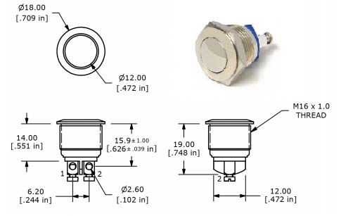
DORAN MFG LLC SLEEPING CHILD CHECK
HOW IT WORKS
Doran Manufacturing’s Sleeping Child Check (SCC) is an electronic device that, when
armed, is designed to force the bus driver to walk to the back of the bus and de-activate
the system before leaving the vehicle. If the driver fails to do so, and exits the bus
through the front door, the horn will immediately sound.
Doran designed this unique system with the children’s safety in mind. Leaving a child
on an empty school bus at the end of a route would create a nightmare for the
youngster, his family and the school district.
Doran’s Sleeping Child Check gives you the peace of mind in knowing that the bus
driver cannot deactivate the system without first walking to the back of the bus - virtually
eliminating the possibility that a child will be left behind.
1) What is included?
Doran Mfg. Sleeping Child Check module (1)
Re-set Switch (1)
2) What you will need:
Wiring Instructions- find online at www.doranmfg.com
Electric drill and 5/8” drill bit
Test Light Probe.
16 or 14 gauge wire, Automotive GXL, SLX or equivalent
Insulated female quick-connectors for .250” blades
Wire stripper/crimper
Basic hand tools
Wire ties
Automotive-grade insulated wire splices or equivalent
Loctite® (non-permanent, serviceable) or equivalent
(2) # 10 self tapping screws
SCC-AM-SW-00 switch (see page 11 of this manual to determine if it is
required for you application)
Optional if needed (Additional isolated door jam switches for Conversion
vans and Mini buses)
These are considered general instructions for the Sleeping Child Check module.
To ensure proper and reliable function of this product, the Sleeping Child Check
must be installed according to the directions. Some variation may be required
depending on the manufacturer of your specific bus. Contact Doran
Manufacturing or visit our website at www.doranmfg.com for questions or
comments regarding these instructions.
Please follow the testing procedure upon completion of installation of
the Doran Sleeping Child Check listed on page 10 of this manual.
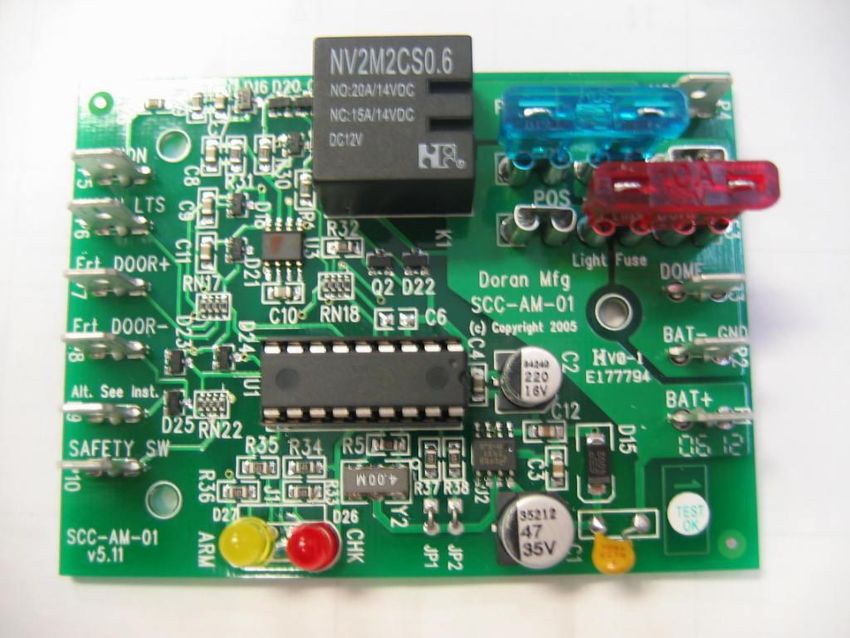
1TYPICAL WIRING CONNECTION TO SCC MODULE
Fig. 1
Insulated female Quick-Connector for .250” wide blades
crimped to 16-gauge wire.
SLEEPING CHILD CHECK WIRING OPTIONS
(12V SCC Model pictured)
Option #1
Chassis Ground – When grounded, horn sounds immediately upon probing
OPTIONAL AUDIBLE ALARM
V(+) battery OR LAMP AS SHOWN
LEFT OR RIGHT RED V(+) battery
WARNING SIGNAL ARMING
SIGNAL INPUT
V(+) battery
IGNITION 1157 or
ACCESSORY POWER equivalent
OVERHEAD
GND HORN (P4)
RED WARNING
FLASHER
SCC-AM DOME LIGHT OUTPUT
(F2) IS FUSED FOR 10 AMPS MAXIMUM.
A RELAY WILL BE REQUIRED FOR
CIRCUITS GREATER THAN 10 AMPS.
(F3)
FRONT DOOR
SWITCH DOME (P3)
DOME LIGHTS
BAT- GND (P2)
GND
V(+) battery
RESET SWITCH, BAT+ (P1)
at Rear of Bus GND
GND
GND
(See Section IlI for detailed wiring instructions)
2Option #2
Horn sounds when connected to Positive(+) V
OPTIONAL AUDIBLE ALARM
OR LAMP AS SHOWN
V(+) battery
LEFT OR RIGHT RED
WARNING SIGNAL ARMING
SIGNAL INPUT
V(+) battery
IGNITION
ACCESSORY POWER 1157 or
equivalent
OVERHEAD
GND
RED WARNING
FLASHER
HORN (P4)
(F2)
GND GND
(F3)
FRONT DOOR
SWITCH DOME (P3) V(+) battery
BAT- GND (P2)
DOME LIGHTS
GND
V(+) battery
RESET SWITCH, BAT+ (P1) SCC-AM DOME LIGHT OUTPUT
at Rear of Bus IS FUSED FOR 10 AMPS MAXIMUM.
A RELAY WILL BE REQUIRED FOR
GND CIRCUITS GREATER THAN 10 AMPS.
GND
Option #3
CONVERSION VANS / MINIBUSES
OPTIONAL AUDIBLE ALARM
OR LAMP AS SHOWN
V(+) battery
LEFT OR RIGHT RED
WARNING SIGNAL ARMING
SIGNAL INPUT
V(+) battery
IGNITION
ACCESSORY POWER 1157 or
equivalent
OVERHEAD
GND
RED WARNING
FLASHER
HORN (P4)
FRONT DOOR JAMB SWITCH - (F2)
GND GND
DRIVER SIDE
(F3)
GND
DOME (P3) V(+) battery
BAT- GND (P2)
DOME LIGHTS
GND
FRONT DOOR JAMB SWITCH -
PASSENGER SIDE DOOR
V(+) battery
RESET SWITCH, BAT+ (P1)
SCC-AM DOME LIGHT OUTPUT
at Rear of Bus IS FUSED FOR 10 AMPS MAXIMUM.
GND A RELAY WILL BE REQUIRED FOR
GND CIRCUITS GREATER THAN 10 AMPS.
(See Section IIl for detailed wiring instructions)
3INSTALLATION INSTRUCTIONS
l. Physical Installation
Locate the module where it is convenient to access most of the signals in the list below.
Make sure that it does not interfere with the driver’s ability to control the vehicle.
Electrical connections are made with insulated female quick connect terminals for .250”
blades. Don’t permanently mount the module until the connections and testing are
completed.
Connections List
P1 – Constant Battery +, Connect to fused (10-15A) un-switched Battery Positive
P2 – Battery Ground –, Connect to un-switched Battery Negative or Common
P3 – Interior Passenger Lights Control
P4 – Horn Control
P5 – Ignition / Accessory Input
P6 – System Arm Input
P7 – Front Door +
P8 – Front Door –
P9 – alternate to shared P8 connection through isolation diode- not usually used,
see troubleshooting section and figure 6.
P10 – Safety, System Reset
II. Basic Operation
Inputs
P1 & P2:
The SCC requires constant battery power. When inactive (sleep mode), the unit draws
less than 3 mA (0.003A) from the battery.
The fuses on the module protect the relays and the load, and also limit current through
BAT+ and BAT-. But if both fuses are in the NEG- position, then the sum of load
currents flows through P2 (BAT-) wiring. If both fuses are in the POS+ position, then
the sum of load currents comes from P1 (BAT+).
Select the battery wire sizes and/or fuse accordingly.
P5 – Connect to Ignition or Accessory
P6 – Connect to an ARM signal, see instructions below.
P7 & P8: - Use either P7 or P8 or both to signal Front Door open
P7 – Connect to a Front Door signal that goes to battery voltage when the door opens.
P8 – Connect to a Front Door switch terminal that grounds when the door opens.
P9 – Usually not used, if there is a problem, see troubleshooting section and figure 6.
P10 – Connect to a dedicated Safety System Reset push button at the rear of vehicle.
Outputs
P4 – Horn control, relay contact to either Battery POS (+) or Battery GND (-).
P5 – Interior coach light control, relay contact to either Battery POS (+) or Battery GND
(-).
The Polarity Fuses on the module select the choice of relays 1) grounding contact or 2)
battery positive contact. The choice depends on control voltages needed to activate the
horn and light.
4Arming
To ARM the SCC and activate the system, a positive battery voltage signal must be
detected at the ARM (P6) terminal with the Ignition on. An example signal to ARM the
unit is the voltage for the Red Warning lights on the top of a bus or the control voltage
for the Stop Arm Sign. Typically these are activated by a front door switch when the
door is opened to load or unload students/passengers. It only takes one event to ARM
the SCC. Once armed, the module will have to be reset via the Safety Switch input,
either before the alarm goes off or after.
No Warning Lights
When a vehicle does not have warning lights, etc., it is still necessary to ARM the
system to activate the required end-of-trip check. Often the Ignition signal or brake
signal is used to ARM the module in this circumstance. It does mean however, that
every time the vehicle is ARMed with ignition, the SCC system will require deactivation
at the end of the trip. (See “Timer Options” for another alternative.)
For testing and trouble shooting, when the SCC is in ARMed state the Yellow LED is
illuminated on the printed circuit board.
Safety System Alarm and System Reset/Deactivate
At the end of the trip, the ignition input will be turned off. If the system is ARMed, the
overhead passenger light relay turns on indicating the vehicle must be checked and
SCC deactivated before exiting. This output may also be used for a remote visual or
audio indicator/reminder for the driver/operator. (See figure)
Example of External Check Bus Indicator
The front door input(s) must remain in the “door closed” condition or state to deactivate
the system by pressing and releasing the reset push button at the rear of the vehicle.
This is required either with or without the ALARM active. If the monitor is not in the
ALARM state, the interior light relay will flash the lights twice to indicate successful
deactivation, and then remain on for 1 minute. If the ALARM has been triggered,
5successful reset will turn off the ALARM output and the interior light control will remain
on for 1 minute.
If the ALARM has not been triggered, the ignition input (or alt. accessory input) may be
turned on and the SCC will return to the ARMed state, interior light relay opens and
front door may be open and closed without triggering ALARM.
For testing and trouble shooting, when system is ARMed with the ignition input off, the
SCC is in “Check Vehicle” state and the Red LED on the printed circuit board will be
flashing.
With the ignition (or alt. accessory) input off and monitor ARMED and if front door(s) is
opened before SCC Reset is pressed, the horn output signal will begin cycling on and
off. This will continue until the door(s) is/are closed and the SCC Reset button is
pressed and released.
For testing and trouble shooting, when the SCC is in ALARM state the Red LED on the
printed circuit board is illuminated and not flashing.
IlI. Wiring Instructions
POWER - P1 (Battery +)
Make a connection from P1 (“Bat +” terminal on the SCC) to constant Pos(+) battery
voltage. With the ignition turned OFF, use a test probe to locate a wire with constant
positive voltage(+).
GROUND - P2 (Battery -)
Make a connection from P2 (“Bat -” terminal on the SCC) to a chassis ground.
HORN - P4 (Horn Out)
Make a connection from P4 (“Horn” terminal on the SCC) directly to the horn relay
wire. This wire will output Pos (+) V or ground signals to energize the school bus
relay.
To test if the horn is activated by a Pos (+)Vbattery or ground connection, locate
the horn wire (usually found at the base of the steering column). Follow these
steps:
a) Connect the alligator clip on the test light probe to any metal surface that is a
chassis ground.
b) Probe the wire you believe carries the horn signal with the test light probe. Do
not press horn button.
Option #1~ Chassis Ground Horn Activation
If the horn sounds immediately upon probing, you have found the correct wire. This may
cause the test light to be dimly lit. If you press the horn button and the light goes out,
you can be certain that the horn is activated by the ground signal. The Horn Fuse (F2)
should be in the NEG- Polarity position.
6Option #2~ Pos (+) V Battery Horn Activation (most common)
If you find a wire that lights up the test light when the horn button is sounded, you have
most likely found the correct wire and can be fairly certain that it requires Pos(+) V to
activate the horn. The Horn Fuse (F2) should be in the POS+ Polarity position.
Horn Fuse Position
Option #1 Option #2
Ground Activation Battery + Activation
Fuse (F2) to NEG- Fuse (F2) to POS+
Accessory or Ignition Power - P5 (Ignition)
Make a connection from P5 (“Ignition” terminal on the SCC) to accessory power. To
determine if the accessory wire receives Pos (+) V, turn the ignition key to the “ON” or
“ACCESSORY” position, and probe the wire. The test light should come on. Turn the
ignition key “OFF” and the test light should turn off.
Arm Input - P6 (Warning Lights)
Make a connection to P6 (“Warning LTS” terminal on the SCC) from either the left or
right overhead red warning light output wires from the flasher unit. If Warning Light
signal is not available, see p6 “ARMING”.
Door - P8 (Frt_Door -)
A. STANDARD CONVENTIONAL BUSES:
Make a connection from P8 (“Frt_DOOR-” terminal on the SCC) to the Front
Door Switch. A convenient place to connect to the switch may be at the
flasher unit, which uses the door switch. Frt_DOOR- is expecting a ground
when the door begins to open. Frt_DOOR+ pin P7 may be used if Bat(+)V is
present when the door is opened.
B. CONVERSION VANS / MINI BUSES:
Buses with multiple (front) door exits, such as conversion vans or minibuses,
require the SCC’s P8 terminal to be connected to both the driver side and
passenger side front door switches. In some cases, additional doorjamb
switches (normally closed) may be required for one or both front doors. Select
a doorjamb switch (SPST - normally closed) that is compatible with the bus
and properly mount in the doorjamb. Open and close the door to make sure
the switch is operating and make any necessary adjustments to ensure
proper switch operation. Wire pin P8 of the SCC-AM to one side of the
switch, the vehicle’s chassis ground to the other side. For the schematic,
please refer to WIRING OPTION 3 in SECTIONI of this manual. Doorjamb
switches are readily available and can be purchased at most auto-parts
stores.
Reset Switch - P10 (Safety Switch)
Make a connection from P10 (“SAFETY SW” terminal on the SCC) and run the wire to
the rear interior of the bus where you plan to mount the reset switch. To mount the
reset switch, refer to Section lll, “Reset Switch Installation.”
7Interior Overhead Light – P3 (Dome)
In some vehicles the interior lights may be controlled by vehicle electronics. In these
vehicles it may not be possible to use the SCC’s DOME light control. If there is a
Grounding or Bat+ voltage control that activates the interior lights, it may be possible to
parallel the SCC with the control or possibly by supplying Bat + voltage to an aux. relay
or supplying Bat + to a light string, etc. Consult manufacturer’s service representatives
for assistance.
A. STANDARD CONVENTIONAL BUSES:
The SCC-AM module is configured to turn on the vehicle’s interior overhead
lights to aid the driver in inspecting the bus as the driver walks to the rear of
the bus and back. The interior overhead light function is fused at 10 Amperes
and can source or sink current depending on the position of the fuse. If the
interior overhead lights draw more current than the fuse/relay can handle, an
additional relay or relays can be used to increase the current capacity. (See
Figure 2).
To use this feature, you will need to determine how the manual switch
activates these lights. Find the wire going to the lights from the switch. With
a test light or buzzer check the voltage to the light string from the switch
outside. Using the following table, determine if the switch is sinking/grounding
or sourcing the lights.
FROM BUS MANUAL SWITCH OR RELAY
(AT BATTERY VOLTAGE WHEN ON) DOME LIGHTS
V(+) battery
FUSE NC
NO
RELAY
TO DOME (P3)
FUSE (F3) TO POS +
GND GND
FIGURE 2
Example of using an auxiliary relay for
high current capability.
Overhead Light Test
Grounding Sourcing
(F3 to NEG-) (F3 to POS+)
Light Switch Off Buzzer/Light On Buzzer/Light Off
Light Switch On Buzzer/Light Off Buzzer/Light On
Move the 10 Amp. Light Fuse (F3) to indicated position (See Table). Wire terminal P3
from the SCC to the circuit connected to the interior overhead light switch.
B. CONVERSION VANS / MINI BUSES:
To use the interior overhead light feature with vans, it is important the door
switch circuit and interior overhead light circuits are isolated from each other.
For example, if the door switches directly ground the dome lights to make
8them come on, then the relay in the Sleeping Child Check will ground the
dome lights exactly like the doors. At the input to the SCC FRT DOOR- this
would indicate a door has opened and trip the alarm when the ignition is
turned off. For this condition, it will be necessary to install separate door
switches for the Sleeping Child Check or not use/wire the overhead light
feature.
Figure 3 shows an example of a relay isolated circuit like may be found on some vans.
The polarity fuse position is determined the same way as described for a standard bus,
see A in Interior Overhead Light section above.
TO DOME (P3)
FUSE (F3) TO POS +
V(+) battery
NC
NO DOME LIGHTS
RELAY
TO SCC (P8)
FRONT DOOR
DOOR
SWITCHES
GND
GND GND
FIGURE 3
Example of relay isolated Dome Lights and Door Switches
C. CONVERSION VANS / MINI BUSES W/0 WARNING FLASHERS
Use ignition/accessory or brake light input at the ARM terminal P6.
This usually means the system will need to be reset after any
startup.
Where driver usually must exit through driver door instead of
passenger door, use end of trip 1 minute timer option as ALARM
delay to allow the driver to reenter vehicle, check that the vehicle is
empty and reset the monitor.
A 10 minute ARM timer option may be used with or instead of a
typical ARM signal. For cases / situations where the typical ARM
signal is not available or used, an optional 10 minute timer will ARM
the monitor after 10 minutes with the ignition/accessory on.
lV. Reset Switch Installation
The Reset switch (Figure 4) included with the Sleeping Child Check will need to be
installed in the rear interior of the school bus. Be sure there is adequate access space
behind the chosen location before installing the switch. An electric drill and 5/8” drill bit
are required for installation.
9Figure 4
Cut-away view of Reset Switch Installation
Drill 5/8” hole in access panel in the rear interior of the bus.
Thread hex nut onto threaded stem.
Insert switch through hole as shown.
Adjust hex nut to proper depth to secure switch properly.
Make a connection from chassis ground (at the rear of the bus) to one
terminal of the reset switch.
Make a connection from P10 wire to the other terminal or the reset switch.
Apply Loctite® (non-permanent, serviceable) to exposed threads.
Thread cap onto threaded stem and tighten securely.
V. Installation Testing for the SCC Monitor
The inspection procedure listed below should be followed at the completion of the
installation.
1) Start the school bus. Make sure all the doors are closed.
2) Activate the Red warning light flashers and open the door. The “YELLOW” LED
will light on the circuit board to show the system is armed.
3) Turn off the Red warning light flashers and close the door.
4) Turn the ignition key to the “OFF” position. The “RED” LED will blink and the
interior overhead lights will come on (if the overhead light option is hooked up)
5) Open the front door. The “RED” LED will stay on and the horn should cycle on
and off.
6) Close the front door and walk to the back of the bus. Depress the reset switch. If
functioning properly, this will disarm the Sleeping Child Check module and the
horn should deactivate. Both LEDs will go out on the printed circuit board. The
interior overhead lights will remain on for one minute if this option is installed.
NOTE: (alarm will not deactivate with front door open).
10VI. Air Door Switch option #SCC-AM-SW-00
This option is required for buses equipped with power-assisted doors whose 8-way
warning lamp flasher units are not activated by a mechanical door switch. For these
buses, the SCC monitor will not function when the emergency release valve is used to
dump the air from the system. To determine if this switch option will be required please
perform the following procedure:
Turn the ignition ON.
Close the front door.
Activate the Amber warning lights.
Open the front door’s emergency release valve to dump the air from the system.
Walk over to the front door
Manually push the front door open.
Walk to the outside of the bus and check to see if the Red warning lights have
been activated.
If the Red warning lights are not flashing, then the air door switch option #SCC-
AM-SW is required (Figure 5)
If the SCC-AM-SW-00 switch is required to be installed, please
follow the instructions below:
COMMON (COM) TERMINAL
BRACKET
MINATURE SWITCH
NORMALLY CLOSED (NC) TERMINAL ROLLER ARM
Figure 5
SCC-AM-SW-00 Switch
Remove the panel above the air door.
Bend and/or twist the switch bracket and firmly mount the SCC-AM-SW-00
switch assembly in a position where the switch’s roller arm is fully engaged
when the air door is fully closed. Excessive force applied to the switch’s roller
arm can cause damage to the switch. Because of this, the switch bracket
should not deflect more than 1/32” when the roller arm is fully engaged.
Connect the switch’s common (COM) terminal to the SCC monitor’s front door
terminal #P8.
Connect the switch’s normally closed (NC) terminal to a chassis ground.
Close the door and inspect the switch making sure the switch’s roller arm is
completely engaged.
Open the front door and inspect the switch. The switch’s roller arm should
spring back to its original resting position.
Follow the procedure in SECTION V to test the air door switch. This will
ensure that it is functioning properly.
11VIl. Periodic Testing for the SCC Monitor
The inspection procedure listed below should be followed at the completion of the
installation, and periodically to ensure the SCC is functioning properly.
1. Start the school bus. Make sure all the doors are closed.
2. Activate the Red warning light flashers and open the door.
3. Turn off the Red warning light flashers and close the door.
4. Turn the ignition key to the “OFF” position.
5. Overhead dome lights should come on if option is hooked up.
6. Open the front door. The horn should cycle on and off.
7. Close the front door and walk to the back of the bus. Depress the reset switch. If
functioning properly, this will disarm the Sleeping Child Check module and the
horn should deactivate. NOTE:(alarm will not deactivate with front door open).
VIII. Timer Options
Two (2) timer options are available, 1) a 10 minute ARM timer and 2) a 1 minute
ALARM (Horn) timer.
Timer ARM Mode
The ARM Timer causes the module to ARM when the IGNITION/ACCESSORY input
(P5) is active continuously for 10 minutes. The module may also be ARMed the usual
way by a Battery Voltage signal on the ARM terminal (P6) if it is connected.
Some states require an additional way to ARM the module for field trips, shuttles and
other group trips when the warning lights may not be activated during loading or
unloading. Activating or ARMing the module after 10 minutes of travel or engine idling
is acceptable.
The ARM Timer options might be used with vehicles such as vans that don’t have
warning lights, or other means to indicate passengers are boarding, and as an
alternative to ARMing by ignition on.
Timer ALARM Mode
The ALARM Timer triggers the ALARM output 1 minute after the IGNITION input is
turned off when the monitor is in an ARMed state. If a Front Door input(s) is connected,
opening the door will still trigger an ALARM. The doors must be closed to deactivate
the monitor.
This timer mode allows a maximum of 1 minute to deactivate the monitor before an
ALARM is triggered. Some states require the 1 minute maximum deactivation time.
When it is necessary that the driver open his door and enter the vehicle by another
door, this could be an alternative method to assure a vehicle is checked at end-of-trip by
depending on the ALARM Timer to trigger the HORN ALARM after a 1 minute delay and
don’t connect/use the P7 or P8 door input(s).
12These two (2) timer modes are independently enabled. The Doran
Sleeping Child Check (SCC-AM) may be ordered with options already
enabled. Or users may enable timers themselves; however some
disassembly may be required to properly access the programming
jumpers. If damage occurs from this procedure, Doran will not
warrant the product.
Selecting Timer Options
Jumper
JP1* Open/cut JP1 for Horn ALARM to be triggered 1 Minute after Ignition Off
JP2* Open/cut JP2 will ARM module after 10 continuous minutes with Ignition Input On.
The module may be ARMED either way when P6 is used in this mode.
*Note: For the 24 volt model, pcb versions before 1.11, the instructions for JP1 and JP2 are
reversed due to mislabeling. Pictured is the 12 volt model.
Open JP1 for 1 Min. after stop
ALARM timer.
Open JP2 for 10 Min. ARM
timer.
13IX. Troubleshooting
Problem Solution
Horn does not activate when I turn off accessory
Check the connection on the horn relay wire. Verify that you have
power and open the front door, but I can hear a
made a secure connection.
relay inside the SCC module clicking on and off.
Horn does not activate when I turn off
accessory power and open the If the front door switch is activates+12V/+24V at the output, the door switch
front door, and I do not hear any relays wire should read “0” Volts when the door is closed, and +12V or +24V when
clicking inside the SCC module. the door is open, then P7 on the SCC should be used. If the front door switch
is grounds the switch output, the door switch wire should read +5 to
+12V/+24V when the door is closed, and “0” Volts when the door is open. In
this case the door switch wire should be connected to P8.
Horn activates immediately when the (1.) Sometimes another device is connected to the same door switch and it
ignition/accessory switch is turned off. “grounds” the SCC door input through “leakage” when the power is off to the
device (sometimes the flasher unit will cause this). In this case the SCC door
input must be isolated from the other device(s), or a separate door switch or
contact must be used for the SCC. A diode has been provided on the SCC
that may provide isolation from the other device. (See Fig. 6)
After the grounding door switch is directly connected to the SCC, connect the
other device (flasher) to P9. Retest the operation of each device, as the
device attached to P9 will not go completely to 0V when the door switch is
grounded.
(2.) Door Switch is wired in conjunction with dome lights and a (new) dooro
jamb Switch is required to activate SCC-AM properly
(3.) Check that door is not open or ajar causing the system to go to
into warning mode
Horn does not activate when I turn off accessory Check that the monitor has been ARMED. The yellow LED should be
power and open the front door, and I do not illuminated. If not illuminated, check ARM input (P6) “Warn LTS” that
hear any relays clicking inside the SCC module. must receive a Bat + logic high after the ignition input is on.
DETACH AND INSULATE WIRE
TO FLASHER UNIT DOOR INPUT
FRONT DOOR
SWITCH
GND
RECONNECT TO FLASHER DOOR INPUT
TO RESET SWITCH at Rear of Bus
FIGURE 6
14You can also read