EtherNet/IP Parallel Redundancy Protocol - Application Technique Original Instructions - Literature Library ...
←
→
Page content transcription
If your browser does not render page correctly, please read the page content below

Application Technique
Original Instructions

EtherNet/IP Parallel Redundancy Protocol
EtherNet/IP Parallel Redundancy Protocol Application Technique

Summary of Changes
This publication contains the following new or updated information. This list includes substantive updates only and is not intended to reflect
all changes.
Topic                                                                                             Page
Added FLEX 5000 I/O to topology drawings                                                          throughout
Revised topology example for redundancy between a PRP network and Layer 3 network                 15
Specified port type for infrastructure switch ports that connect to RedBoxes                      16
Added unsupported topologies                                                                      17…19
Added configuration requirement for LAN A and LAN B infrastructure switches                       16, 33, 38
Revised guidance for infrastructure switches in PRP systems using Precision Time Protocol (PTP)   23
Add CLI configuration for UTC offset value in certain PTP configurations                          24
Added publications to Additional Resources table                                                  43

2                                             Rockwell Automation Publication ENET-AT006D-EN-P - August 2021
Table of Contents
                                  Summary of Changes. . . . . . . . . . . . . . . . . . . . . . . . . . . . . . . . . . . . . . . . . . . . . . . . . . . . 2

                                  Preface . . . . . . . . . . . . . . . . . . . . . . . . . . . . . . . . . . . . . . . . . . . . . . . . . . .5
                                  About This Publication . . . . . . . . . . . . . . . . . . . . . . . . . . . . . . . . . . . . . . . . . . . . . . . . . . . 5
                                  Download Firmware, AOP, EDS, and Other Files . . . . . . . . . . . . . . . . . . . . . . . . . . . . . . . 5

                                  Chapter 1
Parallel Redundancy Protocol      PRP Network Operation . . . . . . . . . . . . . . . . . . . . . . . . . . . . . . . . . . . . . . . . . . . . . . . . . . 7
                                      Comparison of PRP and DLR. . . . . . . . . . . . . . . . . . . . . . . . . . . . . . . . . . . . . . . . . . . 7
                                  PRP Network Topologies . . . . . . . . . . . . . . . . . . . . . . . . . . . . . . . . . . . . . . . . . . . . . . . . . 8
                                      Basic PRP Network Topology . . . . . . . . . . . . . . . . . . . . . . . . . . . . . . . . . . . . . . . . . . 8
                                      PRP Network Topology with LANs as Clouds . . . . . . . . . . . . . . . . . . . . . . . . . . . . . . 9
                                      PRP Network Topology with SAN and VDANs. . . . . . . . . . . . . . . . . . . . . . . . . . . . . . 10
                                      PRP Network Topology with VDANs in a Device Level Ring. . . . . . . . . . . . . . . . . . . 11
                                      PRP Network Topology with Multiple VLANs . . . . . . . . . . . . . . . . . . . . . . . . . . . . . . 12
                                      PRP Network Topology with VLAN Trunking . . . . . . . . . . . . . . . . . . . . . . . . . . . . . . 13
                                      PRP Network Topology with a ControlLogix Redundancy System . . . . . . . . . . . . . 14
                                      Network Redundancy Between PRP Network and Layer 3 Network. . . . . . . . . . . . 15
                                  LAN A and LAN B Topologies . . . . . . . . . . . . . . . . . . . . . . . . . . . . . . . . . . . . . . . . . . . . . . 16
                                      Requirements . . . . . . . . . . . . . . . . . . . . . . . . . . . . . . . . . . . . . . . . . . . . . . . . . . . . . . 16
                                      Recommendations . . . . . . . . . . . . . . . . . . . . . . . . . . . . . . . . . . . . . . . . . . . . . . . . . . 16
                                  LAN A and LAN B Infrastructure Switches . . . . . . . . . . . . . . . . . . . . . . . . . . . . . . . . . . . 16
                                  Unsupported Topologies . . . . . . . . . . . . . . . . . . . . . . . . . . . . . . . . . . . . . . . . . . . . . . . . . 17
                                      Invalid Connections Between LAN A and LAN B . . . . . . . . . . . . . . . . . . . . . . . . . . . 17
                                      Invalid Layer 2 Connections . . . . . . . . . . . . . . . . . . . . . . . . . . . . . . . . . . . . . . . . . . . 18
                                      Single Points of Failure Between Adjacent PRP Networks . . . . . . . . . . . . . . . . . . . 19

                                  Chapter 2
Configure a PRP Network           Device IP Addresses. . . . . . . . . . . . . . . . . . . . . . . . . . . . . . . . . . . . . . . . . . . . . . . . . . . . . 21
                                  Frame Sizes for LAN A and LAN B Devices . . . . . . . . . . . . . . . . . . . . . . . . . . . . . . . . . . . 21
                                  Configuration for LAN A and LAN B Infrastructure Switches. . . . . . . . . . . . . . . . . . . . . 21
                                  Spanning Tree Protocol (STP) . . . . . . . . . . . . . . . . . . . . . . . . . . . . . . . . . . . . . . . . . . . . 22
                                  Multicast Traffic and IGMP Querier . . . . . . . . . . . . . . . . . . . . . . . . . . . . . . . . . . . . . . . . 22
                                  CIP Sync Time Synchronization (Precision Time Protocol) . . . . . . . . . . . . . . . . . . . . . 23
                                  Configuration Example. . . . . . . . . . . . . . . . . . . . . . . . . . . . . . . . . . . . . . . . . . . . . . . . . . 25
                                       Configure the Stratix 5400 RedBox . . . . . . . . . . . . . . . . . . . . . . . . . . . . . . . . . . . . 26
                                       Configure the Stratix 5400 Switch in LAN A . . . . . . . . . . . . . . . . . . . . . . . . . . . . . 30
                                       Configure the Stratix 5400 Switch in LAN B . . . . . . . . . . . . . . . . . . . . . . . . . . . . . 34
                                       Configure the Stratix 5700 Switch in LAN A. . . . . . . . . . . . . . . . . . . . . . . . . . . . . . 34
                                       Configure the Stratix 5700 Switch in LAN B. . . . . . . . . . . . . . . . . . . . . . . . . . . . . . 38
                                       Assign IP Addresses to the SAN and VDANs . . . . . . . . . . . . . . . . . . . . . . . . . . . . . 38
                                       Assign IP Addresses to the 1756-EN2TP Devices (DANs). . . . . . . . . . . . . . . . . . . . 39
                                       Verify Nodes . . . . . . . . . . . . . . . . . . . . . . . . . . . . . . . . . . . . . . . . . . . . . . . . . . . . . . 40

                           Rockwell Automation Publication ENET-AT006D-EN-P - August 2021                                                                       3
Chapter 3 Diagnostics Warning Status for LAN A and LAN B . . . . . . . . . . . . . . . . . . . . . . . . . . . . . . . . . . . . . . . 41 Additional Resources . . . . . . . . . . . . . . . . . . . . . . . . . . . . . . . . . . . . . . . . . . . . . . . . . . . . . . . . . . . . . . . . . . . . . 43 4 Rockwell Automation Publication ENET-AT006D-EN-P - August 2021
Preface

About This Publication
This manual describes how you can configure a Parallel Redundancy Protocol (PRP) network with a compatible device or switch.

Be sure to understand these concepts and tools:
  • EtherNet/IP™ network design
  • Studio 5000 Logix Designer® application
  • Linx-based software
  • Device Manager or WebUI for Stratix® switches

Download Firmware, AOP, EDS, and Other Files
Download firmware, associated files (such as AOP, EDS, and DTM), and access product release notes from the Product Compatibility and
Download Center at rok.auto/pcdc.

                                      Rockwell Automation Publication ENET-AT006D-EN-P - August 2021                                   5
Notes: 6 Rockwell Automation Publication ENET-AT006D-EN-P - August 2021
Chapter           1
Parallel Redundancy Protocol
Parallel Redundancy Protocol (PRP) is defined in international standard IEC 62439-3 and provides high availability in Ethernet networks.
PRP technology creates seamless redundancy by sending duplicate frames to two independent network infrastructures, which are known as
LAN A and LAN B.

A PRP network includes the following components.
Component                                     Description
LAN A and LAN B                               Redundant, active Ethernet networks that operate in parallel.
Double attached node (DAN)                    An end device with PRP technology that connects to both LAN A and LAN B.
                                              An end device without PRP technology that connects to either LAN A or LAN B.
Single attached node (SAN)                    A SAN does not have PRP redundancy.
Redundancy box (RedBox)                       A switch with PRP technology that connects devices without PRP technology to both LAN A and LAN B.
                                              An end device without PRP technology that connects to both LAN A and LAN B through a RedBox.
Virtual double attached node (VDAN)           A VDAN has PRP redundancy and appears to other nodes in the network as a DAN.
Infrastructure switches                       Switches connected to either LAN A or LAN B that are not configured as a RedBox.

PRP Network Operation
A device with PRP technology has two ports that operate in parallel and attach to LAN A and LAN B. This end device is known as a double
attached node (DAN). During normal network operation, a DAN simultaneously sends and receives duplicate Ethernet frames through both
LAN A and LAN B ports. The receiving node accepts whichever frame arrives first and discards the subsequent copy. If a failure occurs in one
of the paths, traffic continues to flow through the other path uninterrupted with no recovery time.

Unlike other redundancy protocols, such as Spanning Tree Protocol (STP), PRP does not require network reconfiguration.

Comparison of PRP and DLR
PRP is distinct from Device Level Ring (DLR) protocol. The following table summarizes some of the differences between the protocols.
Attribute                             DLR                                                          PRP
Standards organization                ODVA                                                         International Electrotechnical Commission (IEC)
                                                                                                   Multiple -fault tolerance, depending on topology or single-fault
Fault tolerance                       Single-fault tolerance                                       tolerance in the worst case
Infrastructure                        Duplication of infrastructure not required                   Duplication of infrastructure required
Switches                              No minimum requirement                                       Twice as many switches as one network
Topology                              Ring topology                                                Any topology
Switchover time                       Fast recovery time                                           Zero recovery time

                                              Rockwell Automation Publication ENET-AT006D-EN-P - August 2021                                                          7
Chapter 1 Parallel Redundancy Protocol
PRP Network Topologies
A PRP network can have many topologies. This section shows examples of PRP network topologies with these features:
• Basic PRP topology with two switches
• LANs as clouds
• SAN and VDANs
• Device Level Ring for VDANs
• Multiple VLANs
• VLAN trunking
• ControlLogix® redundancy system
• Network redundancy between PRP and a Layer 3 network
Basic PRP Network Topology
The most basic network topology is the same as a star topology, but adds these components:
• End nodes with PRP technology, such as 1756-EN2TP modules and FLEX 5000™ EtherNet/IP™ adapters
IMPORTANT Be sure to configure all devices for PRP before connecting them to the PRP network. For example, FLEX 5000
adapters have different modes for DLR and PRP and must be manually set to PRP mode.
• A second, independent LAN
You can use the 1756-EN2TP in a standard star topology and add a second local area network (LAN) for redundancy later.
1756-EN2TP Module as DAN
DC OUTPUT DC INPUT
DIAG
DIAG
Stratix Switch Stratix Switch
LAN A LAN B
DC INPUT DC OUTPUT
DIAG
DIAG
DC INPUT DC OUTPUT
DIAG
DIAG
FLEX 5000 Adapter as DAN
LAN A
LAN B
1756-EN2TP Modules as DANs
8 Rockwell Automation Publication ENET-AT006D-EN-P - August 2021Chapter 1 Parallel Redundancy Protocol
PRP Network Topology with LANs as Clouds
Each LAN can be more complex than one switch. In the following topology, LAN A and LAN B are clouds to show that they can have different
infrastructures. For example, one LAN can have a few switches in series. The other LAN can have a ring of switches.
1756-EN2TP Module as DAN
DC OUTPUT DC INPUT
DIAG
DIAG
LAN A LAN B
DC INPUT DC OUTPUT DC INPUT DC OUTPUT
DIAG DIAG
DIAG DIAG
FLEX 5000 Adapter as DAN
LAN A
LAN B
1756-EN2TP Modules as DANs
Rockwell Automation Publication ENET-AT006D-EN-P - August 2021 9Chapter 1 Parallel Redundancy Protocol
PRP Network Topology with SAN and VDANs
The following network example shows that you can connect devices without PRP technology to either one or both LANs:
• The HMI device is a SAN that connects only to LAN A.
A SAN does not have PRP network redundancy.
• The I/O, drive, and HMI devices are VDANs that connect to both LAN A and LAN B through a Stratix® 5400 switch that is configured as a
RedBox.
In a star topology, VDANs have PRP network redundancy from the RedBox to both LANs, but not from themselves to the RedBox, as
shown with dotted lines in the following example.
1756-EN2TP Module as DAN
Stratix 5400 Switch I/O as VDAN
as RedBox
DC OUTPUT DC INPUT
DIAG
DIAG
DC OUTPUT DC INPUT DC OUTPUT
DIAG DIAG
DIAG DIAG
SD CARD
HMI as SAN Drive as VDAN
LAN A LAN B
HMI as VDAN
DC INPUT DC OUTPUT DC INPUT DC OUTPUT
DIAG DIAG
DIAG DIAG
FLEX 5000 Adapter as DAN
LAN A 1756-EN2TP Modules as DANs
LAN B
10 Rockwell Automation Publication ENET-AT006D-EN-P - August 2021Chapter 1 Parallel Redundancy Protocol
PRP Network Topology with VDANs in a Device Level Ring
The following network example shows that you can connect a DLR topology to the VDAN side of the RedBox. Each node in the ring becomes a
VDAN.
By using a Stratix 5400 switch as a RedBox, you can configure as many as three rings that can have redundancy through the RedBox.
The 1756-EN2TP module does not have DLR protocol and cannot operate as part of a ring.
1756-EN2TP Module as DAN
I/O as VDAN
DC OUTPUT DC INPUT DC OUTPUT
DC OUTPUT DC INPUT
DIAG DIAG
DIAG DIAG DIAG
DIAG
Stratix 5400 Switch
as RedBox
DLR Topology
SD CARD
HMI as SAN
Drive as
VDAN
LAN A LAN B
HMI as VDAN
DC INPUT DC OUTPUT DC INPUT DC OUTPUT
DIAG DIAG
DIAG DIAG
FLEX 5000 Adapter as DAN
LAN A
LAN B
1756-EN2TP Modules as DANs
Rockwell Automation Publication ENET-AT006D-EN-P - August 2021 11Chapter 1 Parallel Redundancy Protocol
PRP Network Topology with Multiple VLANs
You can segment your PRP network into multiple VLANs. Be sure that both PRP ports of a DAN are connected to the same VLAN. For example,
in the following topology, both PRP ports on the 1756-EN2TP module on the left are on VLAN 1. Both PRP ports of the 1756-EN2TP module on
the right are on VLAN 2.
1756-EN2TP Module as DAN on VLAN 1 1756-EN2TP Module as DAN on VLAN 2
Stratix 5400 Switch as I/O as VDAN on VLAN 2
DIAG
DIAG
DC OUTPUT DC INPUT
DIAG
DIAG
DC OUTPUT DC INPUT
RedBox on VLAN 2
DC OUTPUT DC INPUT DC OUTPUT
DIAG DIAG
DIAG DIAG
SD CARD
Drive as VDAN
on VLAN 2
HMI as SAN
on VLAN 1
HMI as VDAN
LAN A LAN B on VLAN 2
DC INPUT DC OUTPUT DC INPUT DC OUTPUT DC INPUT DC OUTPUT
DIAG DIAG DIAG
DIAG DIAG DIAG
FLEX 5000 Adapter as DAN on VLAN 2
1756-EN2TP Module 1756-EN2TP Modules
as DAN on VLAN 1 as DANs on VLAN 2
VLAN 1, LAN A
VLAN 1, LAN B
VLAN 2, LAN A
VLAN 2, LAN B
LAN A
LAN B
12 Rockwell Automation Publication ENET-AT006D-EN-P - August 2021Chapter 1 Parallel Redundancy Protocol
PRP Network Topology with VLAN Trunking
A VLAN trunk is a connection between two devices that carries traffic for multiple VLANs. The following example shows a
Stratix 5400 RedBox with PRP ports configured as trunk ports that carry traffic for both VLANs 1 and 2, and access ports that carry traffic for
either VLAN 1 or 2.
DC OUTPUT DC INPUT
DIAG
DIAG
Stratix Switch, Stratix Switch,
DC OUTPUT DC INPUT DC OUTPUT
DIAG DIAG
LAN A LAN B
DIAG DIAG
SD CARD
SD CARD
Stratix 5400 Switch
as RedBox
SD CARD
Stratix Switch, Stratix Switch,
LAN A LAN B
SD CARD
SD CARD
DC OUTPUT DC INPUT
DIAG
DIAG
VLAN 1
VLAN 2
LAN A Trunk
LAN B Trunk
Rockwell Automation Publication ENET-AT006D-EN-P - August 2021 13Chapter 1 Parallel Redundancy Protocol
PRP Network Topology with a ControlLogix Redundancy System
With redundancy firmware bundle version 31.051, you can use partnered 1756-EN2TP modules in a ControlLogix redundancy system with PRP.
In the following illustration, both LAN A and LAN B are connected to a redundant chassis pair.
For more information about ControlLogix redundancy with PRP networks, see the High Availability Systems Reference Manual, publication
HIGHAV-RM002.
Redundant Chassis Pair with 1756-ENT2P Modules
DC OUTPUT DC INPUT DC OUTPUT
DIAG DIAG
DIAG DIAG
SD CARD
LAN A LAN B
DC INPUT DC OUTPUT DC INPUT DC OUTPUT
DIAG DIAG
DIAG DIAG
LAN A
LAN B
14 Rockwell Automation Publication ENET-AT006D-EN-P - August 2021Chapter 1 Parallel Redundancy Protocol
Network Redundancy Between PRP Network and Layer 3 Network
The topology example in Figure 1 uses Layer 3 RedBoxes that are configured for first hop redundancy protocol (FHRP) and routing. This
configuration provides the resilient connectivity between the Layer 2 PRP segment and the higher-level network. In this type of topology,
follow these guidelines:
• To avoid a single point of failure, do not use RedBoxes that are configured for FHRP to create VDANs with other end devices.
• Connections between the RedBoxes and PRP segments carry a system size limitation. Be sure to limit the use of these connections.
For details about how to configure this type of topology, see the following publications:
• PlantPAx DCS Configuration and Implementation User Manual, publication PROCES-UM100
• Deploying Parallel Redundancy Protocol within a Converged Plantwide Ethernet Architecture, ENET-TD021
Figure 1 - PRP and Layer 3 Network
Plant-wide Network
Controller as DAN
DC OUTPUT DC INPUT
DIAG
DIAG
Stratix 5400 RedBox Stratix 5400 RedBox
FHRP Active FHRP Standby
SD CARD
SD CARD
HMI as SAN
HMI as SAN
DC OUTPUT DC INPUT
DIAG
DIAG
Stratix 5800 RedBox
FLEX 5000 I/O FLEX 5000 I/O
LAN A
LAN B
Layer 3
Rockwell Automation Publication ENET-AT006D-EN-P - August 2021 15Chapter 1 Parallel Redundancy Protocol
LAN A and LAN B Topologies
LAN A and LAN B can have different topologies that are comprised of different network components. Optimal results depend on many
factors, such as network bandwidth, network speed, switch performance, and the rate of transfer for PRP packets.
Requirements
IMPORTANT To maintain network redundancy, never connect LAN A and LAN B directly to each other. A PRP network converges only
at a DAN or a RedBox.
DC OUTPUT DC INPUT
DIAG
DIAG
LAN A LAN B
DC INPUT DC OUTPUT DC INPUT DC OUTPUT
DIAG DIAG
DIAG DIAG
Be sure that your LAN A and LAN B topologies follow these requirements:
• A DAN must be connected to the same IP subnet in LAN A and LAN B. For example, you cannot use the two ports on the 1756-EN2TP as
two NICs connected to two different subnets.
• LAN A and LAN B must have separate, independent infrastructures. For example, both LANs cannot share a switch.
Recommendations
As a best practice, follow these recommendations for LAN A and LAN B topologies:
• Keep both LANs similar in topology, network speed, network latency, and hops.
• Use either wired or wireless networks for both LANs. For example, do not use a wired network for LAN A and wireless network for
LAN B.
• If you use a DLR topology within LAN A or LAN B, be sure to validate your DLR topology within the larger network before production use.
Depending on your network architecture, DLR topology limitations can exist.
LAN A and LAN B Infrastructure Switches
An infrastructure switch is part of either LAN A or LAN B, but not both. Unlike a RedBox, an infrastructure switch does not require built-in PRP
technology. Follow these guidelines:
• On switch downlink ports, enable the PortFast feature for Spanning Tree Protocol (STP) to improve recovery time.
• As a best practice, use managed switches as infrastructure switches for their network diagnostic and configuration capabilities.
• You must use infrastructure switches that support the maximum transmission time (MTU) of 1506 bytes or greater.
16 Rockwell Automation Publication ENET-AT006D-EN-P - August 2021Chapter 1 Parallel Redundancy Protocol
Unsupported Topologies
IMPORTANT Depending on your network architecture, PRP topology limitations can exist.
Be sure to validate your PRP topology within the larger network before production use.
Invalid Connections Between LAN A and LAN B
Only connect LAN A and LAN B with the following:
• DAN devices configured for PRP
• RedBoxes on PRP-enabled ports
Figure 2 illustrates three types of invalid connections between LAN A and LAN B:
• Do not connect a switch in LAN A to a switch in LAN B.
• Do not use a non-RedBox switch or non-PRP ports on a RedBox switch to connect LAN A and LAN B.
• Do not use an EtherNet/IP device that does not support PRP, such as an Ethernet tap or 1756-EN2TR device, to connect LAN A and
LAN B.
Figure 2 - Invalid Connections between LAN A and LAN B
DC OUTPUT DC INPUT
DC OUTPUT DC INPUT
DIAG
DIAG
DIAG
DIAG
Switch-to-Switch Connection
Ethernet Tap
Com
Com Com
IN2
Ref IN2 IN2
Com
IN1 Ref Ref
IN1 IN1
IN2
Ref
IN1
Com
Com Com
IN2
Ref IN2 IN2
Com
IN1 Ref Ref
IN1 IN1
IN2
Ref
IN1
DC INPUT DC OUTPUT
DIAG
DIAG
Com Com
Com Com
IN2 IN2
Ref Ref IN2 IN2
Com
IN1 IN1 Ref Ref
IN1 IN1
IN2
Ref
IN1
Non-RedBox Switch or
non-PRP ports on a RedBox 1756-EN2TR Device
Com
Com Com
IN2
Ref IN2 IN2
Com
IN1 Ref Ref
IN1 IN1
IN2
Ref
IN1
LAN A
LAN B
Rockwell Automation Publication ENET-AT006D-EN-P - August 2021 17Chapter 1 Parallel Redundancy Protocol
Invalid Layer 2 Connections
Figure 3 shows unsupported Layer 2 connections. If RedBoxes connect either directly or through additional infrastructure via Layer 2, your
network can experience uncontrollable loop and broadcast storms.
Figure 3 - Invalid Layer 2 Connections between RedBoxes
Layer 2 Connections
RedBox RedBox RedBox RedBox
SD CARD
IES
SD CARD
IES
SD CARD
IES
SD CARD
DC OUTPUT DC INPUT
DIAG
DC OUTPUT DC INPUT
DIAG
DIAG
DIAG
IES
LAN A
LAN B
18 Rockwell Automation Publication ENET-AT006D-EN-P - August 2021Chapter 1 Parallel Redundancy Protocol
Single Points of Failure Between Adjacent PRP Networks
Figure 4 shows two PRP networks that are connected to the same ControlLogix chassis. To avoid single points of failure in a redundant
system, be aware of these communication limitations:
• Allow the ControlLogix chassis that is connected to both PRP networks to originate, but not bridge traffic between PRP networks.
• Do not allow devices in PRP network 1 communicate with devices in PRP network 2.
Figure 4 - Avoid Single Points of Failure with Adjacent PRP Networks
PRP Network 1 PRP Network 2
LAN A1
Allow ControlLogix devices to originate, but not
bridge traffic between two PRP networks. LAN A2
DC OUTPUT
DIAG
DIAG DC INPUT DC OUTPUT
DIAG
DIAG
DC INPUT DC OUTPUT
DIAG
DIAG
LAN B1
LAN B2
LAN A
LAN B
Rockwell Automation Publication ENET-AT006D-EN-P - August 2021 19Chapter 1 Parallel Redundancy Protocol Notes: 20 Rockwell Automation Publication ENET-AT006D-EN-P - August 2021
Chapter          2
Configure a PRP Network
A PRP network has requirements and restrictions for the following:
  • Device IP addresses
  • Frame sizes
  • LAN A and LAN B infrastructure switches
  • Spanning Tree Protocol (STP)
  • Multicast traffic and IGMP querier
  • CIP Sync™ time synchronization (Precision Time Protocol)

  IMPORTANT       Be sure that all Stratix® switches in your PRP network follow the network guidelines that are described in the user
                  manual for the switches.

Device IP Addresses
To enable devices to communicate with each other across a PRP network, device IP addresses must meet these requirements:
  • To communicate with each other, double attached nodes (DANs) and single attached nodes (SANs) must have unique IP addresses
      within the same subnet.
  • Devices in LAN A and LAN B, including SANs and infrastructure switches, must have unique IP addresses within and between each
      LAN.

Unique IP address assignments also enable you to access each device for monitoring and diagnostics.

Frame Sizes for LAN A and LAN B Devices
PRP adds to the size of Ethernet frames that flow through devices in LAN A and LAN B. If PRP causes frames to exceed the size limit on a
device, the frames are dropped. To accommodate a full-sized packet with the PRP trailer attached, set the maximum transmission unit (MTU)
size on all infrastructure devices to at least 1506 bytes. This MTU value is not required for a switch that is configured as a RedBox.
If you cannot configure the MTU for an infrastructure device, we recommend that you exclude the device from the path of PRP traffic.

Configuration for LAN A and LAN B Infrastructure Switches
On all ports of LAN A and LAN B infrastructure switches that are in the possible path to the IGMP querier, you must specify the multicast
router VLAN ID and the interface to the multicast router.

To configure this information on a switch, use the Cisco® command-line interface (CLI) to run the following command:

switch(config)#ip igmp snooping vlan  mrouter interface

                                       Rockwell Automation Publication ENET-AT006D-EN-P - August 2021                                       21
Chapter 2 Configure a PRP Network
Spanning Tree Protocol (STP)
You must enable the following STP features:
• Enable BPDU Filtering on the RedBox ports that belong to the PRP channel.
When you configure PRP ports on the RedBox, BPDU Filtering is automatically enabled.
• Enable PortFast on the following ports:
- On downlink ports that connect to end devices (not switches)
- On ports that connect RedBoxes to infrastructure switches
PortFast is not recommended on ports between infrastructure switches.
PortFast is enabled by default on Stratix managed switches. Also, the following Smartport roles on Stratix managed switches
automatically enable PortFast:
- Automation Device
- Multiport Automation Device
- Desktop for Automation
- Virtual Desktop for Automation
- Router for Automation
- Phone for Automation
Multicast Traffic and IGMP Querier
For PRP networks with multicast traffic, follow these guidelines:
• If your PRP network includes a RedBox and you want to enable multicast traffic filtering on both LANs, configure IGMP querier on the
RedBox.
• To avoid one point of failure with the loss of a querier, configure at least two queriers in the PRP network.
• Disable IGMP querier on each infrastructure switch in LAN A and LAN B. This requirement applies to PRP networks with or without a
RedBox.
IMPORTANT After a LAN in a PRP network encounters a fault and is then repaired, there is a delay in multicast traffic redundancy.
The delay lasts until the IGMP querier reinstates the multicast traffic. Multicast traffic redundancy is typically restored
within 2 minutes after the LAN is repaired.
22 Rockwell Automation Publication ENET-AT006D-EN-P - August 2021Chapter 2 Configure a PRP Network
CIP Sync Time Synchronization (Precision Time Protocol)
EtherNet/IP™ networks configured for Parallel Redundancy Protocol (PRP) support CIP Sync. CIP Sync devices implement the doubly attached
clock model with Layer 3 End-to-End protocol, as specified in IEC 62439-3, Annex A and C.
In the following illustration, two 1756-EN2TP modules operate as doubly attached clocks operating on LAN A and LAN B redundant networks:
• In the 1756-EN2TP module at the top, both ports A and B are paired and function as CIP Sync master ports. For master operation, both
ports A and B operate as master ports as defined by the IEEE-1588 PTP protocol.
• In the 1756-EN2TP module at the bottom, both ports A and B are paired and function as CIP Sync slave ports. For slave operation, one
port is the active port and operates as defined by the IEEE-1588 Precision Time Protocol (PTP). The active port tunes the clock and
reports its state as SLAVE. The other port is passive and reports its state as PASSIVE_SLAVE. The passive port also measures path
delay and maintains close synchronization to the active port. A network failure on the active port results in a smooth clock transition
from passive to active slave.
DC OUTPUT DC INPUT
DIAG
DIAG
1756-EN2TP Module as Doubly
Attached Clock with Master Ports
(1) (2)
LAN A LAN B
(3) (4)
DC OUTPUT DC INPUT
DIAG
DIAG
1756-EN2TP Module as Doubly
Attached Clock with Slave Ports
Note Port PTP Role
1 Master
2 Master
3 Slave active
4 Slave passive
Rockwell Automation Publication ENET-AT006D-EN-P - August 2021 23Chapter 2 Configure a PRP Network
For PRP systems with CIP Sync time synchronization, follow these guidelines:
• Grandmaster—The Grandmaster for a PRP network can be one of the following:
- A DAN that functions as a doubly attached clock
- A controller that accesses the PRP network via a DAN
- A VDAN that connects to a RedBox
- A switch that is configured as a DAN or RedBox
For time sync critical applications, consider adding redundant Grandmasters.
• Infrastructure switches—Set the PTP clock mode on infrastructure switches in LAN A and LAN B that support CIP Sync as follows:
- For a single VLAN, use Transparent mode.
- For multiple VLANs, use Boundary mode. Also, make the PTP priority lower (higher numerical value) than any other dual connected
device.
• RedBox switch—On each switch you configure as a RedBox, be sure that the PTP mode is set to Boundary or NTP-PTP Clock mode.
These modes are the only PTP modes that are supported on a switch that is configured as a RedBox. Typically, NTP-PTP mode is
configured on the Layer 3 RedBox switches that are connected to the plant-wide network.
If the PTP mode on the RedBox is NTP-PTP Clock mode, use the Cisco command-line interface (CLI) to configure the UTC offset value
to 37 seconds: switch(config)#utc-offset 37
• Time Sync object—Additional support for PRP is provided by the CIP™ Time Sync object:
- A port in the PASSIVE_SLAVE state is reported as enumeration 10 in attribute 12 of the Time Sync Object.
- A doubly attached clock on the PRP network reports the profile identity in attribute 24 as 00-15-4e-00-01-50.
24 Rockwell Automation Publication ENET-AT006D-EN-P - August 2021Chapter 2 Configure a PRP Network
Configuration Example
This configuration example shows you how to configure the PRP system shown in the following illustration:
• The system includes DANs, a SAN, a RedBox, VDANs, and multiple VLANs.
• Because a drive is part of the PRP system, PTP is required.
This example shows the simplest method for configuring PRP trunking with two VLANs. For details on how to configure management
interfaces, native VLANs, and data VLANs, see the PlantPAx Distributed Control System Infrastructure Configuration User Manual, publication
PROCES-UM001.
1756-EN2TP Module as DAN
DC OUTPUT DC INPUT
DIAG
DIAG
LAN A
LAN B
Gi1/5 Gi1/5 I/O as VDAN
Stratix 5400 Switch Stratix 5400 Switch DIAG
DC OUTPUT DC INPUT
DIAG
DC OUTPUT
LAN A LAN B
DIAG DIAG
SD CARD
SD CARD
Stratix 5400 Switch
Gi1/6 Gi1/1
Gi1/1 as RedBox
Gi1/2
HMI as SAN Gi1/2
Gi1/2
Fa1/5
SD CARD
Gi1/1 Fa1/6 Drive as VDAN
Fa1/2 Fa1/2
Stratix 5700 Switch Stratix 5700 Switch
LAN A LAN B
Com Com
IN2 IN2
Ref Ref
IN1 IN1
Fa1/4 Fa1/4
DC OUTPUT DC INPUT
DIAG
DIAG
LAN A
LAN B
VLAN 501
VLAN 502
1756-EN2TP Module as DAN
LAN A Trunk
LAN B Trunk
To configure the example PRP network, complete the following procedures. For more configuration details, see these publications:
• EtherNet/IP Network Configuration User Manual, ENET-UM001
• Stratix Managed Switches User Manual, publication 1783-UM007
IMPORTANT Before you connect cables between devices in a PRP system, complete the configuration of all devices. For example, if
your system includes a FLEX 5000 EtherNet/IP adapter, make sure that the adapter is in PRP mode.
IMPORTANT Before you begin, be sure to update the devices with the latest firmware.
Rockwell Automation Publication ENET-AT006D-EN-P - August 2021 25Chapter 2 Configure a PRP Network
Configure the Stratix 5400 RedBox
The RedBox in the example on page 25 uses the port configurations that are shown in the following table. Also, because the RedBox is
connected to a drive, PTP must be enabled and set to Boundary mode.
Table 1 -
Port Connected Device VLAN IP Address with Subnet Mask Native VLAN(1) Administrative Mode Smartport Role PortFast
Stratix 5400 switch, LAN A 501 192.168.10.14/24
Gi1/1 301 Trunk — —
502 192.168.20.24/24
Stratix 5400 switch, LAN B 501 192.168.10.12/24
Gi1/2 301 Trunk — —
502 192.168.20.22/24
Fa1/5 I/O, VDAN 501 192.168.10.101/24 — Access Automation Device Enabled
Fa1/6 Drive, VDAN 502 192.168.20.201/24 — Access Automation Device Enabled
(1) All trunk ports require the same native VLAN.
To configure this example, follow these steps.
1. Run Express Setup in Short Press mode and assign a default IP address of 192.168.10.11.
26 Rockwell Automation Publication ENET-AT006D-EN-P - August 2021Chapter 2 Configure a PRP Network
2. Assign the Automation Device Smartport role to the switch ports connected to the VDANs (Fa1/5 and Fa1/6).
The Smartport role enables PortFast on the ports. PortFast is required to be enabled on ports that are connected to end devices.
3. Add VLANs 301 and 502.
VLAN 502 has a unique IP address of 192.168.20.21.
Rockwell Automation Publication ENET-AT006D-EN-P - August 2021 27Chapter 2 Configure a PRP Network
4. Assign VLAN 501 to port Fa1/5 connected to the I/O (VDAN) and assign VLAN 502 to port Fa1/6 connected to the drive (VDAN).
5. Choose Boundary mode for PTP.
28 Rockwell Automation Publication ENET-AT006D-EN-P - August 2021Chapter 2 Configure a PRP Network
6. Add a PRP channel group with this configuration:
• Choose Trunk as the Administrative mode because the ports carry traffic for VLANs 501 and 502.
• Choose 301 as the native VLAN.
7. Verify that the Automation Device Smartport role automatically enabled PortFast on the ports that are connected to end devices.
Rockwell Automation Publication ENET-AT006D-EN-P - August 2021 29Chapter 2 Configure a PRP Network
8. Enable IGMP querier.
Configure the Stratix 5400 Switch in LAN A
The Stratix 5400 switch in LAN A in the example on page 25 uses the port configurations that are shown in the following table. Also, the
system and jumbo MTU values on the switch must be set to 1506. PTP must be enabled and set to End to End Transparent mode.
Table 2 -
Port Connected Device VLAN IP Address with Subnet Mask Native VLAN(1) Administrative Mode Smartport Role PortFast
501 192.168.10.11/24
Gi1/1 Stratix 5400 RedBox 301 Trunk — —
502 192.168.20.21/24
501 192.168.10.15/24
G1/2 Stratix 5700 switch, LAN A 301 Trunk — —
502 192.168.20.25/24
Gi1/5 1756-EN2TP as DAN 501 192.168.10.102/24 — Access Automation Device Enabled
Gi1/6 HMI as SAN 501 192.168.10.103/24 — Access Automation Device Enabled
(1) All trunk ports require the same native VLAN.
To configure this example, follow these steps.
1. Run Express Setup in Short Press mode and assign a default IP address of 192.168.10.14.
30 Rockwell Automation Publication ENET-AT006D-EN-P - August 2021Chapter 2 Configure a PRP Network
2. Assign the Automation Device Smartport role to the switch ports connected to end devices (Gi1/5 and Gi1/6).
The Smartport role enables PortFast on the ports. PortFast must be enabled on ports that are connected to end devices.
3. Add VLANs 301 and 502.
VLAN 502 has a unique IP address of 192.168.20.24.
Rockwell Automation Publication ENET-AT006D-EN-P - August 2021 31Chapter 2 Configure a PRP Network
4. For ports Gi1/1 and Gi1/2, configure these settings:
• Choose Trunk as the Administrative mode because the ports carry traffic for VLANs 501 and 502.
• Choose 301 as the native VLAN.
5. Verify that the Automation Device Smartport role automatically enabled PortFast on the ports that are connected to end devices.
32 Rockwell Automation Publication ENET-AT006D-EN-P - August 2021Chapter 2 Configure a PRP Network
6. Set the system and jumbo MTU value to 1506, and when prompted, restart the switch.
7. Choose End to End Transparent mode for PTP over one VLAN.
To support PTP over multiple VLANs, you can configure a LAN switch in Boundary clock mode. In Boundary clock mode, the
PTP priority must be lower (higher numerical value) than any other DAN or RedBox.
8. Disable IGMP querier.
9. On all ports that are in the possible path to the IGMP querier, specify the multicast router VLAN ID and the interface to the multicast
router with the following CLI command:
switch(config)#ip igmp snooping vlan mrouter interface
Rockwell Automation Publication ENET-AT006D-EN-P - August 2021 33Chapter 2 Configure a PRP Network
Configure the Stratix 5400 Switch in LAN B
The Stratix 5400 switch in LAN B in the example on page 25 uses the port configurations that are shown in the following table. Also, the
system and jumbo MTU values on the switch must be set to 1506. PTP must be enabled and set to End to End Transparent mode.
To configure this example, use the same procedure as described in Configure the Stratix 5400 Switch in LAN A on page 30 with these port
configurations.
Table 3 -
Port Connected Device VLAN IP Address with Subnet Mask Native VLAN(1) Administrative Mode Smartport Role PortFast
501 192.168.10.11/24
Gi1/1 Stratix 5400 RedBox 301 Trunk — —
502 192.168.20.21/24
501 192.168.10.13/24
G1/2 Stratix 5700 switch, LAN B 301 Trunk — —
502 192.168.20.23/24
Gi1/5 1756-EN2TP as DAN 501 192.168.10.102/24 — Access Automation Device Enabled
(1) All trunk ports require the same native VLAN.
Configure the Stratix 5700 Switch in LAN A
The Stratix 5700 switch in LAN A in the example on page 25 uses the port configurations that are shown in the following table. Also, the
system and jumbo MTU values on the switch must be set to 1506. PTP must be enabled and set to End to End Transparent mode.
Table 4 -
Port Connected Device VLAN IP Address with Subnet Mask Native VLAN(1) Administrative Mode Smartport Role PortFast
501 192.168.10.14/24
Gi1/2 Stratix 5400 switch, LAN A 301 Trunk — —
502 192.168.20.24/24
Fa1/4 1756-EN2TP as DAN 502 192.168.20.202/24 — Access Automation Device Enabled
(1) All trunk ports require the same native VLAN.
To configure this example, follow these steps.
1. Run Short Press mode Express Setup and assign an IP address of 192.168.10.15.
34 Rockwell Automation Publication ENET-AT006D-EN-P - August 2021Chapter 2 Configure a PRP Network
2. Assign the Automation Device Smartport role to the switch port connected to the 1756-EN2TP module (Fa1/4).
The Smartport role enables PortFast on the ports. PortFast must be enabled on all ports that are connected to end devices.
3. Add VLANs 502 and 301.
VLAN 502 has a unique IP address of 192.168.21.25.
Rockwell Automation Publication ENET-AT006D-EN-P - August 2021 35Chapter 2 Configure a PRP Network
4. Assign VLAN 502 to port Fa1/4 connected to the 1756-EN2TP module.
5. For port Gi1/2, configure these settings:
• Choose Trunk as the Administrative mode because the port carries traffic for VLANs 501 and 502.
• Choose 301 as the native VLAN.
36 Rockwell Automation Publication ENET-AT006D-EN-P - August 2021Chapter 2 Configure a PRP Network
6. Verify that the Automation Device Smartport role automatically enabled PortFast on the port that is connected to an end device.
7. Set the system MTU value to 1506, and then prompted, restart the switch.
8. Disable IGMP querier.
Rockwell Automation Publication ENET-AT006D-EN-P - August 2021 37Chapter 2 Configure a PRP Network
9. Choose End to End Transparent mode for PTP over one VLAN.
To support PTP over multiple VLANs, you can configure a LAN switch in Boundary clock mode. In Boundary clock mode, the
PTP priority must be lower (higher numerical value) than any other DAN or RedBox.
10. On all ports that are in the possible path to the IGMP querier, specify the multicast router VLAN ID and the interface to the multicast
router with the following CLI command:
switch(config)#ip igmp snooping vlan mrouter interface
Configure the Stratix 5700 Switch in LAN B
The Stratix 5700 switch in LAN B in the example on page 25 uses the port configurations that are shown in the following table. Also, the
system and jumbo MTU values on the switch must be set to 1506. PTP must be enabled and set to End to End Transparent mode.
To configure this example, use the same procedure as described in Configure the Stratix 5700 Switch in LAN A on page 34 with these port
configurations.
Table 5 -
Port Connected Devices VLAN IP Address with Subnet Mask Administrative Mode Smartport Role PortFast
501 192.168.10.12/24
Gi1/2 Stratix 5400 switch, LAN B Trunk — —
502 192.168.20.22/24
Fa1/4 1756-EN2TP as DAN 502 192.168.20.202/24 Access Automation Device Enabled
Assign IP Addresses to the SAN and VDANs
The SAN and VDAN devices in the example on page 25 use the configurations that are shown in the following table.
Assign IP addresses to the devices. No further configuration is required.
Table 6 -
Device IP Address with Subnet Mask Connected Device VLAN
HMI as SAN 192.168.10.103/24 Stratix 5400 switch, LAN A 501
I/O as VDAN 192.168.10.101/24 Stratix 5400 RedBox 501
Drive as VDAN 192.168.20.201/24 Stratix 5400 RedBox 502
38 Rockwell Automation Publication ENET-AT006D-EN-P - August 2021Chapter 2 Configure a PRP Network
Assign IP Addresses to the 1756-EN2TP Devices (DANs)
The 1756-EN2TP devices in the example on page 25 use the port configurations shown in the following tables.
Assign IP addresses to the devices. No further configuration is required.
Table 7 -
Device IP Address with Subnet Mask Port Connected Device VLAN
Stratix 5400 switch, LAN 501
LAN A A
1756-EN2TP 192.168.10.102/24
Stratix 5400 switch, LAN 501
LAN B B
Device IP Address with Subnet Mask Port Connected Device VLAN
LAN A Stratix 5700 switch, LAN A 502
1756-EN2TP 192.168.20.202/24
LAN B Stratix 5700 switch, LAN B 502
Rockwell Automation Publication ENET-AT006D-EN-P - August 2021 39Chapter 2 Configure a PRP Network Verify Nodes Once your PRP network configuration is complete and cables are connected between the devices, the RedBox automatically learns the MAC IDs of connected devices. You can verify and monitor these connected devices in the Device Manager web interface for the RedBox. 40 Rockwell Automation Publication ENET-AT006D-EN-P - August 2021
Chapter       3
Diagnostics
These diagnostic methods are available for a PRP network:
  • For a Stratix® 5400 or 5410 switch that is configured as a RedBox, the Device Manager web interface provides statistics for PRP nodes.
      For more information, see the Stratix Managed Switches User Manual, publication 1783-UM007.
  • For a Stratix 5800 switch that is configured as a RedBox, the WebUI provides statistics for PRP nodes. For more information, see the
      Stratix 5800 Managed Switches User Manual, 1783-UM012.
  • For a 1756-EN2TP module operating as a DAN, the diagnostic webpages provide statistics for ports A and B. For more information, see
      the EtherNet/IP Network Configuration User Manual, publication ENET-UM001.
  • For LAN A and LAN B status, you can configure the controller to send a message to the 1756-EN2TP module as described in page 41.
For more diagnostic attributes, see the ODVA documentation at www.odva.org.

Warning Status for LAN A and LAN B
In the Studio 5000 Logix Designer® application, you can configure a controller message to determine a warning status for these conditions in
LAN A and LAN B:
   • Loss of communication for 3 seconds on one LAN, but not the other. This condition applies to traffic from all nodes. The condition is
       cleared once communication is restored for 3 seconds.
   • Node status is active on one LAN but not the other. This condition indicates that no packets were received from one of the nodes on
       one of the LANs for 3 seconds. The condition is cleared once packets are received again within 3 seconds.
   • Packets from a wrong LAN were received on one of the ports in the past second. The condition is cleared once no wrong packets are
       received for 1 second.

  IMPORTANT       Cycling power to a device can trigger a PRP warning on the network or the device until the connections to all Ethernet
                  ports are re-established and packets are exchanged for 3 seconds.

When the warning status is active for one of the LANs, the Warning Active indicator displays True in the 1756-EN2TP web interface.

                                       Rockwell Automation Publication ENET-AT006D-EN-P - August 2021                                      41
Chapter 3 Diagnostics
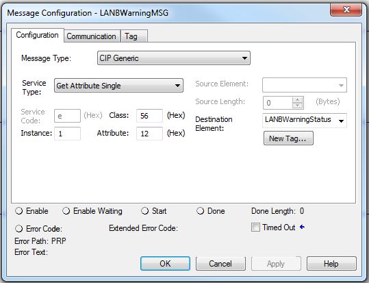
To obtain a warning status for LAN A and LAN B, configure a controller message to send to the 1756-EN2TP module. Use the following
parameters. The data type for this CIP™ message is DINT.
Field Parameter
Message Type CIP Generic
Service Type Get Attribute Single
Class 56 (Hex)
Instance 1
11 (Hex) for LAN A
Attribute 12 (Hex) for LAN B
Figure 5 - LAN A Warning Message
Figure 6 - LAN B Warning Message
42 Rockwell Automation Publication ENET-AT006D-EN-P - August 2021EtherNet/IP Parallel Redundancy Protocol Application Technique
Additional Resources
These documents contain additional information concerning related products from Rockwell Automation.
Resource Description
Stratix Ethernet Device Specifications Technical Data, 1783-TD001 Provides specifications for Stratix® Ethernet switches and other devices.
High Availability Systems Reference Manual, HIGHAV-RM002 Provides guidelines for high availability systems, including redundant system components,
networks, and other hardware and software considerations.
Highlights key application requirements, technology, and supporting design considerations
Deploying Parallel Redundancy Protocol within a Converged Plantwide to help with the successful design and deployment of specific use cases within the
Ethernet Architecture, ENET-TD021 Converged Plantwide Ethernet (CPwE) framework. CPwE PRP was architected, tested, and
validated by Cisco® Systems and Rockwell Automation with assistance by Panduit.
EtherNet/IP Device Level Ring Application Technique, Describes Device Level Ring (DLR) topologies, configuration considerations, and diagnostic
publication ENET-AT007 methods.
PlantPAx DCS Configuration and Implementation User Manual, Provides guidelines and procedures for the implementation and configuration of a
publication PROCES-UM100 PlantPAx® distributed control system, including PRP topologies.
Stratix Managed Switches User Manual, 1783-UM007 Describes how to configure, monitor, and troubleshoot Stratix® 5400, 5410, 5700, 8000, 8300,
and ArmorStratix™ 5700 managed switches.
Stratix 5800 Managed Switches User Manual, 1783-UM012 Describes how to configure, monitor, and troubleshoot Stratix 5800 managed switches.
FLEX 5000 EtherNet/IP Adapter User Manual, publication 5094-UM005 Provides information on how to configure and operate FLEX 5000 EtherNet/IP adapters.
ControlLogix EtherNet/IP Network Devices User Manual, ENET-UM004 Describes how to configure and use EtherNet/IP devices to communicate on the EtherNet/IP
network.
EtherNet/IP Network Devices User Manual, ENET-UM006 Describes how to configure and use EtherNet/IP devices to communicate on the EtherNet/IP
network.
Ethernet Reference Manual, publication ENET-RM002 Describes basic Ethernet concepts, infrastructure components, and infrastructure features.
Troubleshoot EtherNet/IP Networks Application Technique, publication Describes troubleshooting techniques for Integrated Architecture products on EtherNet/IP
ENET-AT003 networks.
Provides guidance on how to conduct security assessments, implement Rockwell
System Security Design Guidelines Reference Manual, SECURE-RM001 Automation products in a secure system, harden the control system, manage user access,
and dispose of equipment.
EtherNet/IP Media Planning and Installation Manual
This manual is available from the Open DeviceNet® Vendor Association Describes the required media components for an EtherNet/IP network and how to plan,
(ODVA) at http://www.odva.org. install, verify, troubleshoot, and certify your network.
Industrial Automation Wiring and Grounding Guidelines, publication 1770-4.1 Provides general installation guidelines for a Rockwell Automation industrial system.
Product Certifications website, rok.auto/certifications. Provides declarations of conformity, certificates, and other certification details.
You can view or download publications at rok.auto/literature.
Rockwell Automation Publication ENET-AT006D-EN-P - August 2021 43Rockwell Automation Support Use these resources to access support information. Technical Support Center Find help with how-to videos, FAQs, chat, user forums, and product notification updates. rok.auto/support Knowledgebase Access Knowledgebase articles. rok.auto/knowledgebase Local Technical Support Phone Numbers Locate the telephone number for your country. rok.auto/phonesupport Literature Library Find installation instructions, manuals, brochures, and technical data publications. rok.auto/literature Product Compatibility and Download Center Download firmware, associated files (such as AOP, EDS, and DTM), and access product rok.auto/pcdc (PCDC) release notes. Documentation Feedback Your comments help us serve your documentation needs better. If you have any suggestions on how to improve our content, complete the form at rok.auto/docfeedback. Allen-Bradley, ControlLogix, expanding human possibility, Logix5000, PlantPAx, Rockwell Automation, Stratix, and Studio 5000 Logix Designer are trademarks of Rockwell Automation, Inc. CIP, CIP Sync, DeviceNet, and EtherNet/IP are trademarks of ODVA, Inc. Trademarks not belonging to Rockwell Automation are property of their respective companies. Rockwell Automation maintains current product environmental compliance information on its website at rok.auto/pec. Rockwell Otomasyon Ticaret A.Ş. Kar Plaza İş Merkezi E Blok Kat:6 34752, İçerenköy, İstanbul, Tel: +90 (216) 5698400 EEE Yönetmeliğine Uygundur Publication ENET-AT006D-EN-P - August 2021 ENET-AT006C-EN-P - April 2019 Copyright © 2021 Rockwell Automation, Inc. All rights reserved. Printed in the U.S.A.
You can also read