Sensor Integration Gateway - SIG200 - REST API OPERATING INSTRUCTION - SICK USA
←
→
Page content transcription
If your browser does not render page correctly, please read the page content below
OPERATING INSTRUCTION

Sensor Integration Gateway - SIG200
REST API

Integration Products
Described product
                                   SIG - Sensor integration gateway
                                   SIG200 REST API

                                   Manufacturer
                                   SICK AG
                                   Erwin-Sick-Str. 1
                                   79183 Waldkirch
                                   Germany

                                   Production location
                                   SICK PCA
                                   55438 Minneapolis, MN
                                   USA

                                   Legal information
                                   This work is protected by copyright. Any rights derived from the copyright shall be
                                   reserved for SICK AG. Reproduction of this document or parts of this document is
                                   only permissible within the limits of the legal determination of Copyright Law. Any modi‐
                                   fication, abridgment or translation of this document is prohibited without the express
                                   written permission of SICK AG.
                                   The trademarks stated in this document are the property of their respective owner.
                                   © SICK AG. All rights reserved.

                                   Original document
                                   This document is an original document of SICK AG.

                                                                                                     E497722

2   O P E R A T I N G I N S T R U C T I O N | Sensor Integration Gateway - SIG200                     8024482.1BT0/2021-08-10 | SICK
                                                                                                         Subject to change without notice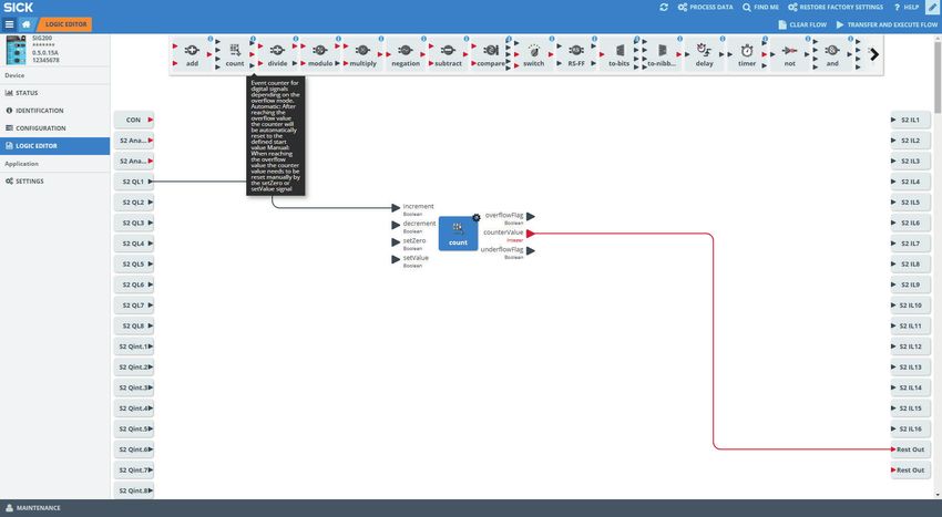
CONTENTS

Contents
                                   1    Safety information............................................................................                           4
                                        1.1      General safety notes................................................................................            4
                                        1.2      Notes on UL approval...............................................................................              4

                                   2    Correct use.........................................................................................                     5

                                   3    Product description...........................................................................                           6
                                        3.1      Product description..................................................................................           6
                                        3.2      Operating and status indicators..............................................................                   6

                                   4    Transport and storage.......................................................................                             8
                                        4.1      Transport...................................................................................................     8
                                        4.2      Transport inspection.................................................................................            8
                                        4.3      Storage......................................................................................................    8

                                   5    Mounting.............................................................................................                    9

                                   6    Electrical installation........................................................................ 10
                                        6.1      Pin alignment............................................................................................       10

                                   7    SIG200 configuration....................................................................... 12
                                        7.1      Operation via Webserver..........................................................................               12
                                        7.2      Operation via SOPAS ET (USB/Ethernet).................................................                          12
                                        7.3      Configuration via REST API.......................................................................               26

                                   8    Device Functions............................................................................... 69
                                        8.1      Overview of the device functions.............................................................                   69
                                        8.2      Data Storage.............................................................................................       71
                                        8.3      Logic Editor................................................................................................    71

                                   9    Troubleshooting................................................................................. 91

                                   10   Disassembly and disposal............................................................... 92

                                   11   Maintenance...................................................................................... 93

                                   12   Technical data.................................................................................... 94
                                        12.1 General technical data.............................................................................                 94

8024482.1BT0/2021-08-10 | SICK                                                   O P E R A T I N G I N S T R U C T I O N | Sensor Integration Gateway - SIG200    3
Subject to change without notice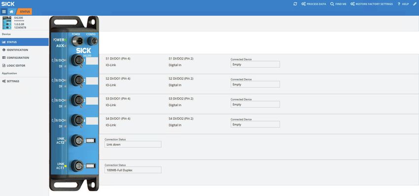
1 SAFETY INFORMATION

1               Safety information
1.1             General safety notes

1.1.1           Safety notes
                                        ■       Read the operating instructions before commissioning.
                                        ■       Connection, mounting, and setting may only be performed by trained specialists.
                                        ■       Not a safety component in accordance with the EU Machinery Directive.
                                        ■       When commissioning, protect the device from moisture and contamination.
                                        ■       These operating instructions contain information required during the life cycle of
                                                the gateway.

                                       CAUTION
                                       This equipment is not intended for use in residential environments and may not provide
                                       adequate protection to radio reception in such environments.

1.2             Notes on UL approval
                                       UL Environmental Rating: Enclosure type 1

4       O P E R A T I N G I N S T R U C T I O N | Sensor Integration Gateway - SIG200                         8024482.1BT0/2021-08-10 | SICK
                                                                                                                 Subject to change without notice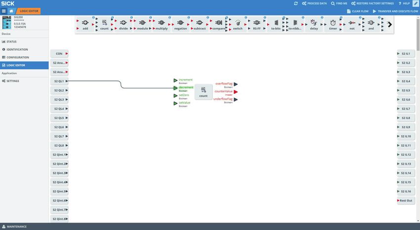
CORRECT USE 2

2                  Correct use
                                   The SIG200 (hereinafter referred to as "module") is an IO-Link master for connecting IO-
                                   Link devices and standard input signals or output signals. This data can be transmitted
                                   to a higher-level system via Ethernet (REST API).
                                   Intended use requires that the device is used industrially indoors without any spe‐
                                   cific climatic and atmospheric requirements. Operation of the device according to its
                                   intended use and enclosure rating IP 67 are only guaranteed if open male and female
                                   connectors are sealed with blind plugs.
                                   If the product is used for any other purpose or modified in any way, all warranty claims
                                   against SICK AG will be void.

8024482.1BT0/2021-08-10 | SICK                                        O P E R A T I N G I N S T R U C T I O N | Sensor Integration Gateway - SIG200   5
Subject to change without notice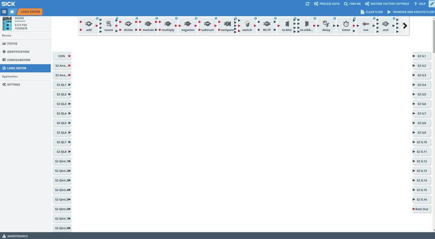
3 PRODUCT DESCRIPTION
3 Product description
3.1 Product description
The IO-Link-Master SIG200 is an intelligent gateway to connect IO-Link devices, input
and/or output signals for signal integration via REST API to a network. It was designed
for use in industrial environments that require up to an IP67 enclosure rating. There are
four IO-Link channels, each on a dedicated Port Type A M12 socket.
In addition, the SIG200 has a powerful user interface that can be accessed either via
USB using the SOPAS ET software from SICK or via Ethernet and any web browser. With
the integrated IODD interpreter, the SIG200 and the connected IO-Link devices can be
parameterized using the IODD file(s). The user interface also has a logic editor that can
be used to parameterize sensor/actuator systems based on the information provided.
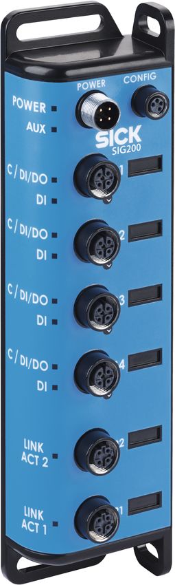
3.2 Operating and status indicators
ß à
POWER CONFIG â
POWER POWER
AUX
1 AUX
9 SIG200
á
/DO S1 C/DI/DO1
DI
2 DI
8
/DO C/DI/DO1
S2
DI DI
3
/DO C/DI/DO1
S3
DI DI
4
/DO C/DI/DO
S4
DI DI
5
LINK LINK
ACT2
P2 ACT2
6
LINK LINK
ACT1
P1 ACT1
7
Figure 1: Dimensional drawing
1 POWER IN
2 IO-Link Port S1
3 IO-Link Port S2
4 IO-Link Port S3
5 IO-Link Port S4
6 Ethernet Port P2
7 Ethernet Port P1
8 DI: LED for pin 2
9 C/DI/DO LED for pin 4
ß Mounting hole for front mounting
6 O P E R A T I N G I N S T R U C T I O N | Sensor Integration Gateway - SIG200 8024482.1BT0/2021-08-10 | SICK
Subject to change without notice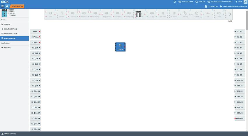
PRODUCT DESCRIPTION 3

                                   à         Mounting hole for side mounting
                                   á         Removable user defined port labels
                                   â         USB Port (M8) for configuration with SOPAS ET

                                   LEDs on the fieldbus module

                                                                                                           LINK
                                                                                                           ACT2
                                                                                                                             P2
                                                  POWER      CONFIG

                                   1
                                   2   AUX                                                                 LINK
                                                                                                                             P1
                                                                                                           ACT1
                                   3                      SIG200

                                   Table 1: LED status indicators
                                   LED                                          Indication                  Meaning
                                   Supply voltage                               green                       Power on
                                                                                dark                        Power off
                                                                                Flashing green              A serious error has occurred. Please con‐
                                                                                                            tact your SICK service partner.
                                   AUX                                          blinking                    Find me
                                   LINK ACT 1 (Link / Activity 1)               dark                        No network connection on port P1
                                                                                green                       Network connection on port P1
                                   LINK ACT 2 (Link / Activity 2)               dark                        No network connection on port P2
                                                                                green                       Network connection on port P2

                                   IO-Link Port LEDs (Port S1-S4)

                                   9                        SIG200
                                         /DO                S1
                                             DI

                                   8

                                   Legend                             LED                           Indication                            Meaning
                                   8                                  DI: LED for pin 2             amber                                 Additional DI on pin 2
                                                                                                    Off                                   No additional DI on
                                                                                                                                          pin 2
                                   9                                  C/DI/DO LED for pin 4 green                                         Pin 4 - IO-Link commu‐
                                                                                                                                          nication active
                                                                                                    green blinking                        Pin 4 - no IO-Link com‐
                                                                                                                                          munication active

8024482.1BT0/2021-08-10 | SICK                                                     O P E R A T I N G I N S T R U C T I O N | Sensor Integration Gateway - SIG200   7
Subject to change without notice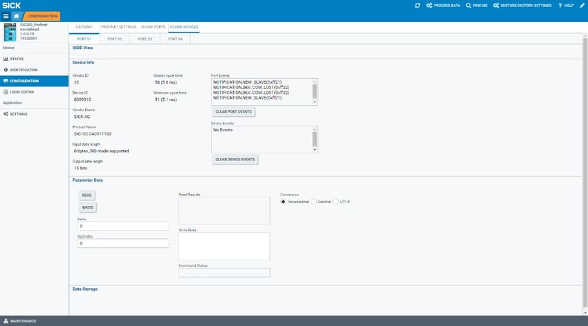
4 TRANSPORT AND STORAGE

4             Transport and storage
4.1           Transport
                                     For your own safety, please read and observe the following notes:

                                     NOTE
                                     Damage to the device due to improper transport.
                                      ■       The device must be packaged for transport with protection against shock and
                                              moisture.
                                      ■       Recommendation: Use the original packaging as it provides the best protection.
                                      ■       Transport should be performed by specialist staff only.
                                      ■       The utmost care and attention is required at all times during unloading and
                                              transportation on company premises.
                                      ■       Note the symbols on the packaging.
                                      ■       Do not remove packaging until immediately before you start mounting.

4.2           Transport inspection
                                     Immediately upon receipt at the receiving work station, check the delivery for complete‐
                                     ness and for any damage that may have occurred in transit. In the case of transit
                                     damage that is visible externally, proceed as follows:
                                      ■       Do not accept the delivery or only do so conditionally.
                                      ■       Note the scope of damage on the transport documents or on the transport compa‐
                                              ny’s delivery note.
                                      ■       File a complaint.

                                     NOTE
                                     Complaints regarding defects should be filed as soon as these are detected. Damage
                                     claims are only valid before the applicable complaint deadlines.

4.3           Storage
                                     Store the device under the following conditions:
                                      ■       Recommendation: Use the original packaging.
                                      ■       Do not store outdoors.
                                      ■       Store in a dry area that is protected from dust.
                                      ■       So that any residual damp can evaporate, do not package in airtight containers.
                                      ■       Do not expose to any aggressive substances.
                                      ■       Protect from sunlight.
                                      ■       Avoid mechanical shocks.
                                      ■       Storage temperature: see "Technical data", page 94.
                                      ■       Relative humidity: see "Technical data", page 94.
                                      ■       For storage periods of longer than 3 months, check the general condition of all
                                              components and packaging on a regular basis.

8     O P E R A T I N G I N S T R U C T I O N | Sensor Integration Gateway - SIG200                       8024482.1BT0/2021-08-10 | SICK
                                                                                                             Subject to change without notice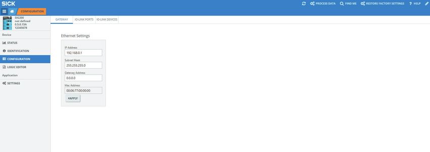
MOUNTING 5

5                  Mounting
                                   The SIG200 is mounted with two screws, maximum M6, and two flat washers.
                                   Observe the maximum permissible tightening torque of 0.8 Nm.

                                                2 x M6
                                                < 0.8 Nm

                                                POWER      CONFIG

                                          AUX

                                                        SIG200

                                   Figure 2: Mounting

                                   Scope of delivery:
                                   •    SIG200
                                   •    5 blind plugs (on Port CONFIG, S2, S3, S4, P1)
                                   •    Quickstart instruction
                                   •    20 labels for the label pocket
                                   To ensure proper ground connection to the housing, the coating on the housing around
                                   the mounting screws must be removed.

                                   NOTE
                                   There can be several SIG200 mounted side by side without observing a minimum
                                   distance between each IO-Link Master.

                                   NOTE
                                   There are no blind plugs at ports P1, S1 and Power.

                                   NOTE
                                   There are no screws inlcuded in the scope of delivery.

8024482.1BT0/2021-08-10 | SICK                                       O P E R A T I N G I N S T R U C T I O N | Sensor Integration Gateway - SIG200   9
Subject to change without notice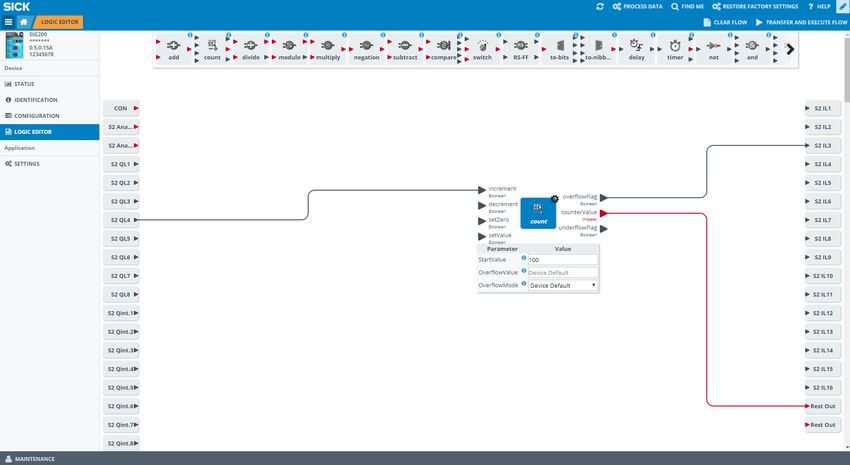
6 ELECTRICAL INSTALLATION

6             Electrical installation
                                     The SIG200 power and IO-Link cables must be connected in a voltage-free state (UV =
                                     0 V). The following information must be observed, depending on the connection type:
                                     Even if the wiring is looped through, the total current of the module must not exceed
                                     3 A.

                                     NOTICE DAMAGE OF EQUIPMENT
                                     Equipment damage due to incorrect supply voltage! Please note the instructions for
                                     electrical installation.

                                     An incorrect supply voltage may result in damage to the equipment. Operation in
                                     short-circuit protected network max. 8 A is allowed.
                                     Only apply voltage/switch on the voltage supply (UV > 0 V) once all electrical connec‐
                                     tions have been established.
                                     Male and female connectors that are not used must be sealed with blind caps so that
                                     the enclosure rating of IP 67 is assured.
                                     Explanation of the connection diagrams:
                                     DI = Digital input
                                     DO = Digital output
                                     FE = functional ground
                                     IO-Link = IO-Link communication (C)
                                     n. c. = not connected
                                     Rx+ = Receiver +
                                     Rx- = Receiver -
                                     Tx+ = Transmitter +
                                     Tx- = Transmitter +

6.1           Pin alignment
                                     UB: 10 ... 30 V DC
                                     Table 2: Power Port, M12 A-coded
                                                         Pin                              Signal            Description
                                                          1                               + (L+)         + 24 V DC nominal
                                                          2                                 n.c.           not connected
                                                          3                                 M                     0V
                                                          4                                 n.c.           not connected
                                                                                      4              3

                                                                                      1              2
                                                                                          IN = 4 A

10    O P E R A T I N G I N S T R U C T I O N | Sensor Integration Gateway - SIG200                       8024482.1BT0/2021-08-10 | SICK
                                                                                                             Subject to change without notice
ELECTRICAL INSTALLATION 6
Table 3: USB Port (for configuration), M8
Pin Signal Description
1 + (L+) + 5 V DC nominal
2 - Data
3 + Data 0 V (logic ground)
4 M
4 2
3 1
Table 4: Profinet Port (P1/P2), M12 D-coded
Pin Signal Description
1 Tx+ Sender +
2 Rx+ Receiver +
3 Tx- Sender -
4 Rx- Receiver -
1 2
4 3
Table 5: IO-Link Ports (S1-S4) M12, A-coded, (Port Class A)
Pin Signal Description
1 + (L+) + 24 V DC nominal
2 DI Configurable as Digital Input
3 M 0 V (logic ground)
4 DI / DO or IO-Link Configurable as Digital Input or
Digital Output or IO-Link
5 n. c.
5
3 4
2 1
8024482.1BT0/2021-08-10 | SICK O P E R A T I N G I N S T R U C T I O N | Sensor Integration Gateway - SIG200 11
Subject to change without notice7 SIG200 CONFIGURATION
7 SIG200 configuration
The SIG200 can be configured via following different methods:
1 Ethernet (Webserver)
2 USB (with SOPAS ET)
3 Ethernet (with SOPAS ET)
4 Ethernet (via REST API)
The integrated web server (1) of the SIG200 provides direct access for parameteriza‐
tion via a suitable web browser on devices connected to the same Ethernet network as
the SIG200.
In addition, the SIG200 can be connected via USB (2) using the SOPAS engineering tool
application from SICK. The required cable (M8, USB) must be ordered separately. It is
also possible to connect the SIG200 to SOPAS ET via Ethernet (3) for parameterization.
The SOPAS engineering tool application can be downloaded from www.sick.com.
The SIG200 also has a REST API interface that provides direct access for higher-level
automation operations. A REST API is a programming interface that defines functions
for making requests and receiving responses via HTTP protocols such as GET and POST
(REST = Representational State Transfer, API = Application Programming Interface).
7.1 Operation via Webserver
The SIG200 can be accessed via the integrated web server. To do so, an IP address
must be set for the SIG200. The SIG200 is shipped from the factory without a preset IP
address. The default setting for IP address assignment is made via the BOOTP protocol.
The following web browsers are supported:
• Microsoft Internet Explorer (version 11 or higher)
• Google Chrome (version 50 or higher)
• Firefox (version 30 or higher)
• Safari (version 9 or higher)
To access the integrated SIG200 web server, start the browser on your device and enter
the IP address of the SIG200.
NOTE
SIG200 only supports HTTP, the HTTPS protocol is not supported.
The layout and functionality of the integrated webserver as accessed by a browser
corresponds to the operation via SOPAS ET (using USB or Ethernet connection), see
"Operation via SOPAS ET (USB/Ethernet)", page 12.
7.2 Operation via SOPAS ET (USB/Ethernet)
With the aid of the SOPAS engineering tool application, the SIG200 can be parameter‐
ized on a computer running Microsoft Windows.
SIG200 configuration with SOPAS ET allows not only to configure the four ports of the
IO-Link Master but also to configure the connected IO-Link devices via an embedded
IODD interpreter.
Additionally, via the Logic Editor (which is a graphical configuration environment) logic
functions across multiple devices which are connected to SIG200 can be created.
12 O P E R A T I N G I N S T R U C T I O N | Sensor Integration Gateway - SIG200 8024482.1BT0/2021-08-10 | SICK
Subject to change without noticeSIG200 CONFIGURATION 7
The physical connection between SOPAS ET (computer) and the SIG200 can be estab‐
lished via USB or Ethernet.
NOTE
Basically, connecting the SIG200 to the computer via Ethernet is recommended. When
using the USB interface, long waiting/loading times may occur for large amounts of
data, as the data transmission rate on the USB interface is limited. Especially when
saving large data flows in the logic editor, there may be connection problems between
SOPAS and the device, meaning that the logic cannot be saved completely via USB.
7.2.1 Opening new project in SOPAS
Connect the SIG200 to your computer and start SOPAS ET. When the program is
started, the Ethernet and USB interfaces are always scanned for connected devices
and devices found are automatically displayed as a new project icon.
If the connected SIG200 does not automatically appear as a new project, check that
the SIG200 is correctly connected to the computer and add the device to the project
manually. To do so, run the device search again. Then select the desired SIG200 in the
search results. Add to the project via drag and drop or double-click. Devices that are
already in the project are grayed out in the search results.
NOTE
Also, make sure you are using the device family search (→ click Search settings . Select
the Device family oriented search and “SIG200” options).
If a SIG200 is inserted into a SOPAS project for the first time, then the corresponding
device driver must be installed. In the project icon, click on the Install device driver button
and either download the required SDD from the SICK homepage www.sick.com or
upload it directly from the device. The uploaded device driver now appears in the device
catalog.
NOTE
Make sure that the device driver available in the device catalog matches the firmware
version of the SIG200 used. If these do not match, uninstall the SDD by right-clicking on
the corresponding entry in the device catalog. Then upload the device driver again as
described above.
If the device status is signaled with OFFLINE in the project icon, then the SIG200
must first be switched online. To do this, click the offline button and synchronize the
parameter values in the project and on the device.
8024482.1BT0/2021-08-10 | SICK O P E R A T I N G I N S T R U C T I O N | Sensor Integration Gateway - SIG200 13
Subject to change without notice7 SIG200 CONFIGURATION
Special user levels can be selected via the REGISTER button. For the standard configura‐
tion of the SIG200, a special login is not required, since the required user levels Run
and Maintenance are already stored in the device (for details see see "User login and
editing mode", page 17).
To parameterize the SIG200, double-click on any point on the project icon.
The device window opens, in which all device parameters are displayed. Here the
parameterization can be carried out, parameters can be loaded into or from the device
or parameter values can be observed.
NOTE
Other functions are available in the context menu of the project icon. To do this, click
on the button with the three dots at the upper right edge of the device tile to open the
context menu.
7.2.2 SOPAS ET overview and standard functions on each page
SIG200 pages have the following common layout:
56 7 1 2 3 8
4
ß
9
àá
Figure 3: SOPAS ET layout
1 Process data
2 FIND ME function (not available for EtherNet/IP variant)
3 RESTORE FACTORY SETTINGS: Reset to factory settings
4 Menu
5 Home
6 STATUS
7 Refresh page
8 Edit mode
9 Page contents
ß Page selection
à Notifications
á User mode
The buttons located in the upper right portion of the interface provide global device
configuration. These buttons will be present on every configuration page.
14 O P E R A T I N G I N S T R U C T I O N | Sensor Integration Gateway - SIG200 8024482.1BT0/2021-08-10 | SICK
Subject to change without noticeSIG200 CONFIGURATION 7
Table 6: Functions
EDIT The EDIT button allows the settings on a given configuration page to be
changed.
The EDIT button will be highlighted light blue when pressed. Pages that can
be configured will be gray until the EDIT mode is activated.
NOTE
1. Click on the Edit button (top right)
2. Click the RUN button (bottom left).
3. Change the operating mode from RUN to MAINTENANCE.
4. Insert the password "main"
5. Now the device parameterization can be changed.
NOTE
For the sake of device cybersecurity, changing the default password is
strongly recommended.
Process data The process data button provides the process data of the connected IO-Link
devices.
8024482.1BT0/2021-08-10 | SICK O P E R A T I N G I N S T R U C T I O N | Sensor Integration Gateway - SIG200 15
Subject to change without notice7 SIG200 CONFIGURATION
FIND ME function When this button is clicked, the AUX LED next to the SIG200 POWER voltage
supply connection flashes at a frequency of 1 Hz until the button is clicked
again. This function can be used to identify devices that have already been
mounted.
NOTE
If the FIND ME function is active, no further interface navigation can take
place until the STOP button has been clicked in the dialog.
RESTORE FAC‐ Clicking on this button the SIG200 will reset all settings to the factory
TORY SETTINGS defaults. As a factory default, all ports are configured as digital inputs.
Selection of the RESTORE FACTORY SETTINGS option must be confirmed again
in the Confirm Action field.
If you click Yes, all settings currently stored in the device are overwritten.
After clicking OK, a Success dialog is displayed to confirm the successful
reset of the connected SIG200 to the factory settings.
NOTE
While both of the dialogues boxes are active, no other interface navigation is
possible.
NOTE
The Restore Factory Settings button works from any of the configuration
pages.
HELP The HELP button can be used to access a help page that is displayed on
each parameterization page on the right side of the user interface. Here
you will find additional information about the SIG200 relating to the current
page.
Please use for more detailed information always the operating manual. The
help texts does not include all information from the operating manual.
NOTE
The HELP screen remains open when you switch the parameterization page
via the tree view with parameterization pages.
16 O P E R A T I N G I N S T R U C T I O N | Sensor Integration Gateway - SIG200 8024482.1BT0/2021-08-10 | SICK
Subject to change without noticeSIG200 CONFIGURATION 7
Menu Click this button to show/hide the Page selection menu to make it easier to
navigate on smaller screens.
NOTE
The button is highlighted light blue when the device tree is hidden.
Home Click the Start button at any time to return to the STATUS device page.
Refresh page Clicking on this button the page contents are refreshed.
Device informa‐ This area on the top left side of the page shows the product name, user-
tion defined location, firmware version, and serial number.
Page contents This area shows the selected page.
SETTINGS On the SETTINGS page, you can change the language and password.
Device notifica‐ SIG200 device notifications will appear on the bottom of the screen. These
tions are informational only for configuration exchanges and errors. Each notifica‐
tion can be acknowledged by clicking on the entry.
RUN Click the RUN button to change the user access level from RUN (read-only)
to MAINTENANCE. The default password is “main”. The device settings on
the CONFIGURATION (parameterization), LOGIC EDITOR and SETTINGS pages can
only be adjusted in MAINTENANCE mode.
NOTE
The device settings on the other pages are grayed out and cannot be
adjusted until MAINTENANCE mode is activated.
Please ensure that you have clicked on the Edit button on the top right
corner as well if you would like to do any configurations.
7.2.2.1 User login and editing mode
To change SIG200 settings, you must log in at the Maintenance user level (read and write
access). By default, you are logged in at the Run (read-only) user level, where you can
only view data and parameterization. If you want to change the user, click on the user
icon at the bottom left of the page. Select the desired user name in the dialog. If a user
other than “Run” is selected, the corresponding password must also be entered.
If the Keep me logged in option is activated, the last user remains saved even if the
parameterization tool (SOPAS ET or web browser) is closed.
NOTE
Saving the user in a web browser may depend on the cookie settings.
8024482.1BT0/2021-08-10 | SICK O P E R A T I N G I N S T R U C T I O N | Sensor Integration Gateway - SIG200 17
Subject to change without notice7 SIG200 CONFIGURATION
The following table shows the available users and their initial password:
Table 7: User / Passwords
User Initial password Role
Run (none) Read configuration
Maintenance main Read and write configuration
Please see "Settings", page 25 for details on changing passwords.
NOTE
As of firmware version 1.2.0, you are automatically prompted to change the password
for the “Maintenance” user when logging in for the first time. Please remember this
password. If you have changed and forgotten the password, contact SICK Service.
If you click Login, you can also change the password of the logged-in user.
NOTE
In terms of cybersecurity of the device, changing the default password of the “Mainte‐
nance” user is strongly recommended.
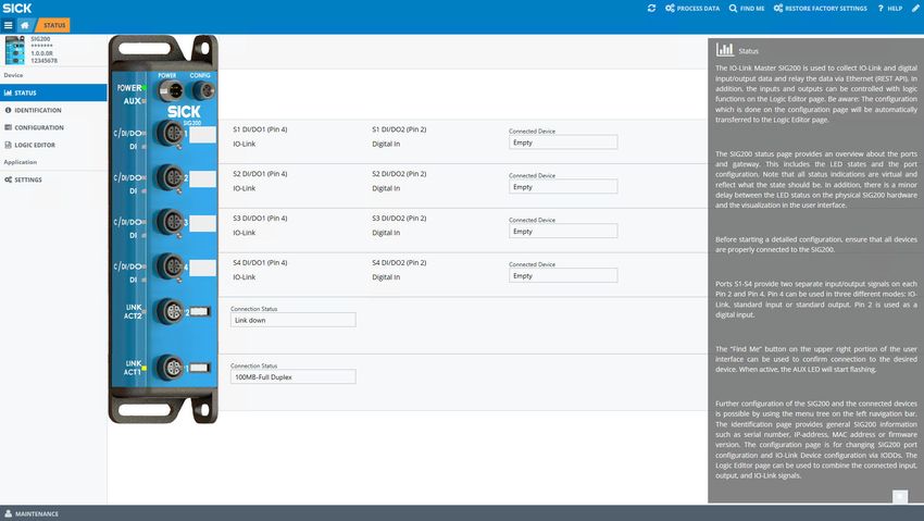
7.2.3 STATUS page
The STATUS page is the home page for the SIG200. It provides an overview of the
current module status and device function.
Figure 4: Status page
The page displays the parameterization of pin 2 (DI) and pin 4 (C/DI/DO) for each port.
The LEDs in the SIG200 figure change their state depending on the current state of the
connected device. The ports correspond to the IO link, input or output settings defined
on the CONFIGURATION (parameterization) page. The port designations correspond to the
user-defined port designations defined on the CONFIGURATION (parameterization) page.
The POWER LED shown in the figure on the left is normally always green to indicate that
the SIG200 is switched on.
The AUX LED is used for the FIND ME (Identify) function.
ACT/LINK1 + 2 indicate if there is Ethernet network connection on either port.
18 O P E R A T I N G I N S T R U C T I O N | Sensor Integration Gateway - SIG200 8024482.1BT0/2021-08-10 | SICK
Subject to change without noticeSIG200 CONFIGURATION 7
NOTE
Note that the LED displays do not work in real time. When the SIG200 is started for the
first time, the device has an initialization time after switching on of approx. 70 seconds
7.2.4 IDENTIFICATION page
The IDENTIFICATION page provides detailed information about the connected SIG200.
These include the product name, serial number and firmware version.
7.2.5 CONFIGURATION page (parameterization)
On the IO-Link Ports tab, the port parameterization for ports S1 to S4 can be changed.
In addition, an IODD file can be uploaded from your computer and assigned to one of
the SIG200 ports (S1 to S4). Therefore, the IODD XML file and the referenced device
image must be packed into a ZIP archive. This follows the same convention used by
the IO-Link community (IODD Finder) and is the preferred method for retrieving the
corresponding device IODDs. In addition, the single IODD can be uploaded as XML file.
Other settings such as the minimum cycle time or the assignment of port designations
can also be made on this page.
On the IO-Link Devices tab there is a page for each IO-Link port (S1-S4). This tab
displays the IODD view, device info and parameter data for each IO-Link device. The
page visualization when an IODD was already uploaded to the user interface is different
to the visualization of the IO-Link device without uploaded IODD file. For a more conven‐
ient use it is recommended to upload the relevant IODD file for the IO-Link devices.
Figure 5: CONFIGURATION page (parameterization)
7.2.5.1 Gateway
The Ethernet settings can be configured on the Gateway tab.
8024482.1BT0/2021-08-10 | SICK O P E R A T I N G I N S T R U C T I O N | Sensor Integration Gateway - SIG200 19
Subject to change without notice7 SIG200 CONFIGURATION
Figure 6: CONFIGURATION page, gateway
NOTE
If the Ethernet settings are changed, device communication may be interrupted.
NOTE
A device power cycle is necessary to activate the ethernet parameter changes.
7.2.5.2 IO-Link ports
On the IO-Link Ports tab, settings of the IO-Link ports that can be used in IO-Link or
standard input/output mode can be configured.
An IODD file can be uploaded here for easy parameterization of the connected IO-Link
device. First upload an IODD file using the Upload IODD button. This IODD is then stored
in the SIG200 Repository .
The disk usage shows how much storage capability on SIG200 is available.
After the correct IODD file has been uploaded, it can be assigned to the port to which
the corresponding device is connected (e.g. port S1). To do this, select the IODD file on
the right side of the table using the drop-down menu. All IODDs already in the Repository
are displayed and the correct one can be selected. If an IODD is to be deleted from the
device, select the desired IODD and click DELETE.
After the desired IODD is selected, confirm by clicking the Apply button. The information
from the IODD is now displayed on the IO-Link Devices tab.
NOTE
The upload of one IODD file takes a few minutes. Depending on the size of the specific
IODD file the upload is faster or slower. It is not unusual in case the IODD upload needs
1-5 minutes or longer untill the IODD is fully visualized in the user interface.
20 O P E R A T I N G I N S T R U C T I O N | Sensor Integration Gateway - SIG200 8024482.1BT0/2021-08-10 | SICK
Subject to change without noticeSIG200 CONFIGURATION 7
Figure 7: CONFIGURATION page, IO-Link ports
The port owner determines who can write process data outputs. This can be set to
either fieldbus, REST or logic editor. When this setting is set to REST, no available
process data outputs are displayed on the LOGIC EDITOR page.
If the fieldbus is the port owner, the minimum process cycle time is as short as possible
and cannot be changed because the port parameterization comes from the PLC.
The Data Storage function can be configured for Restore or Backup + Restore according to
the desired use case. If data storage is to be used, Expected Device ID and Expected Vendor
ID must be set.
NOTE
If an IO-Link port has been configured, click Apply to change the parameterization.
Otherwise, the parameterization will not be sent to the device.
NOTE
If Fieldbus (fieldbus) has been configured as the port owner, the parameterization is set
by the PLC and cannot be changed via the user interface. The corresponding control
surfaces are also grayed out in the Maintenance user level.
NOTE
The state of pin 2 is only mapped to the fieldbus processing data when the port owner
is set to Fieldbus.
7.2.5.3 IO-Link devices
IODD view
The SIG200 user interface is manufacturer-independent and can be used to connect
and visualize IO-Link devices with connection class A from any manufacturer.
The IO-Link devices tab displays the connected IO-Link devices on each port. Make sure
that the correct port (S1 to S4) is selected at the top of the page and that the correct
IODD has been uploaded and assigned to the port.
The page is divided into three parts: Identification (left side), Process data (center) and
Service data (right side).
So this page allows the parametrization of the IO-Link device in an easy way in case a
corresponding IODD file was uploaded before.
8024482.1BT0/2021-08-10 | SICK O P E R A T I N G I N S T R U C T I O N | Sensor Integration Gateway - SIG200 21
Subject to change without notice7 SIG200 CONFIGURATION
NOTE
This page needs some time for loading all IO-Link device data. There is no "loading"
information appearing. It can happen that the visualization needs ~20 s or more untill
all parameters are visualized.
The following figure shows the view in case a corresponding IODD file for an IO-Link
device was uploaded:
Figure 8: CONFIGURATION page, IO-Link devices
NOTE
The correct IODD file must be uploaded and provided in the device configuration for this
section to be displayed.
The following figure shows the view if no IODD file is supplied; default IO-Link parame‐
ters are visualized:
22 O P E R A T I N G I N S T R U C T I O N | Sensor Integration Gateway - SIG200 8024482.1BT0/2021-08-10 | SICK
Subject to change without noticeSIG200 CONFIGURATION 7
Device Info
Provides a device overview of any attached IO-Link device. This section will display the
details of any attached IO-Link sensor regardless of port configuration.
Parameter Data
Use this section to issue individual IO-Link commands to the attached device.
Data Storage
Use the commands in this section for advanced management of an IO-Link devices
data storage.
Upload:
If the IO-Link device is parameterized to Backup/Restore, this button is used to upload
the device parameterization to the local data storage container of the SIG200. If the
IO-Link device is parameterized to Restore, this button deletes the contents of the port
data storage container and reinitializes the port.
NOTE
Be aware that the current configuration is deleted and replaced with the new configura‐
tion from the IO-Link device.
Download / Import / Export:
Export and Import allow you to copy the contents of a port data storage container from
one SIG200 to a second SIG200. Once the contents of the data memory have been
imported into the second SIG200, they can be downloaded to the connected IO-Link
device.
NOTE
If the individual underside for the ports remains empty, then either no IO-Link device is
physically connected to the SIG200 or the connected device is not an IO-Link device.
8024482.1BT0/2021-08-10 | SICK O P E R A T I N G I N S T R U C T I O N | Sensor Integration Gateway - SIG200 23
Subject to change without notice7 SIG200 CONFIGURATION
7.2.6 LOGIC EDITOR page (logic editor)
Figure 9: LOGIC EDITOR page (logic editor)
The LOGIC EDITOR page of SIG200 allows you to apply user-defined logic functions to the
available input signals and transmit the results to various output signals by dragging
and dropping logic blocks and connection cables.
The left side of the screen lists all configured inputs. The upper middle bar contains the
available logic gates that can be dragged down into the workspace. And listed on the
right side are the configured outputs.
Before setting up any logic, it is required to upload the relevant IODD files. This ensures
that the correct inputs and outputs of every connected IO-Link device are displayed
correctly.
NOTE
Note that the screen is grayed out until you change to editing mode (see "User login and
editing mode", page 17).
Creating a logic system
1. To select the desired logic blocks, click and drag them to the working range.
NOTE
If a logic block has been selected incorrectly, or needs to be removed, click on it
and drag it back up to the selection bar. A garbage bin will appear to remove the
selected logic gate from the workspace.
2. Making connections from the inputs to the logic gates: Click on the desired input,
click again and mark the arrow. A connecting line is then created. Note that you
can drag the line to a desired logic gate input.
As you approach, the logic gate inputs expand to accommodate the connection
cable. As soon as the connection is made, the bends (if there are bends along the
connection), the position of the logic gate and the window size can be adjusted.
The connection is scaled automatically. An incorrect connection can be deleted by
clicking and holding the connecting line. A wastebasket icon is displayed at the top
center of the user interface.
Some logic blocks require at least two input signals.
24 O P E R A T I N G I N S T R U C T I O N | Sensor Integration Gateway - SIG200 8024482.1BT0/2021-08-10 | SICK
Subject to change without noticeSIG200 CONFIGURATION 7
Note that the inputs must always be assigned from top to bottom (e.g. for two
inputs A+B and not A+D).
The inputs are outlined in red when connections are made to indicate that a
connection is still required in this area. The two inputs C and D are only active in
the logical truth table if a connection has been made.
NOTE
Green input arrows and green text: a connection is possible
If a connection is not possible, the text will have red color and it is not possible to
drag a connection to the input.
NOTE
Some inputs and logic gates have a small gear indicating that some additional set‐
tings are possible. Clicking on the gear will open the additional settings dialogue
box and allow for additional configuration (e. g. delay time).
3. Clomplete the setup by using the Transfer and Execute Flow button: the new logic
configuration is transfered to the connected SIG200.
NOTE
An error will appear if there are any improper or missing connections. The notifica‐
tion area will indicate a successful transfer.
7.2.7 Settings
The following settings are possible:
Setting Possible values
Language english / german
Figure 10: Settings
The language of the user interface can be selected on the SETTINGS page (German or
English).
Also, if logged in as any user except “Run” (see "User login and editing mode", page 17),
it is possible to change the password for the logged in user.
8024482.1BT0/2021-08-10 | SICK O P E R A T I N G I N S T R U C T I O N | Sensor Integration Gateway - SIG200 25
Subject to change without notice7 SIG200 CONFIGURATION
For security reasons, changing the original default password is strongly recommended.
As of firmware version 1.2.0, you are automatically prompted to change the password
for the “Maintenance” user when logging in for the first time.
If you have changed and forgotten the password please contact SICK service for sup‐
port.
7.3 Configuration via REST API
The SIG200 provides a REST API with JSON data format for accessing the data of the
connected devices.
NOTE
Since firmware version 1.3, the SIG200 has also featured the JSON REST interface
defined by the IO-Link community in addition to the SICK-specific REST API interface.
This is specified in the document “JSON Integration for IO-Link” in version 1.0.0 (Mar
2020 Order No: 10.222).
These operating instructions provide an overview of the available device functions and
the access mechanisms.
26 O P E R A T I N G I N S T R U C T I O N | Sensor Integration Gateway - SIG200 8024482.1BT0/2021-08-10 | SICK
Subject to change without noticeSIG200 CONFIGURATION 7
7.3.1 General Interface description
The REST API is a client – server interface and enables the client to request data from
the server through a defined set of resources. The REST API is stateless which means
that no information about the state of connection and no information about the server
or client are required.
The operation is based on HTTP methods. Common HTTP methods are GET, POST, PUT
and DELETE. JSON, or JavaScript Object Notation, is a minimal, visually readable format
for structuring data. It is mainly used to transmit data between a server and a web
application as an alternative to XML.
Table 8: Overview
Interface see "Interface", page 39
GET/apiversion see "GET/apiversion", page 39
GET/openapi see "GET/openapi", page 39
gateway see "gateway", page 40
GET/gateway/identification see "GET/gateway/identification", page 40
GET/gateway/capabilities see "GET/gateway/capabilities", page 40
GET/gateway/configuration see "GET/gateway/configuration", page 40
POST/gateway/configuration see "POST/gateway/configuration", page 40
GET/gateway/events see "GET/gateway/events", page 41
POST/gateway/reboot see "POST/gateway/reboot", page 42
POST/gateway/reset see "POST/gateway/reset", page 42
IODDs see "IODDs", page 43
GET/iodds see "GET/iodds", page 43
GET/iodds/file see "GET/iodds/file", page 43
POST/iodds/file see "POST/iodds/file", page 44
DELETE/iodds see "DELETE/iodds", page 44
Masters see "Masters", page 44
GET/masters see "GET/masters", page 44
GET/masters / 1/capabilities see "GET/masters / 1/capabilities", page 44
GET/masters / 1/identification see "GET/masters / 1/identification",
page 45
POST/masters / 1/identification see "POST/masters / 1/identification",
page 45
Ports see "Ports", page 45
GET/masters / 1/ports see "GET/masters / 1/ports", page 45
GET/masters / 1/ports/{portNumber}/capabil‐ see "GET/masters / 1/ports/{portNum‐
ities ber}/capabilities", page 46
GET/masters / 1/ports/{portNumber}/status see "GET/masters / 1/ports/{portNum‐
ber}/status", page 46
GET/masters / 1/ports/{portNumber}/configu‐ see "GET/masters / 1/ports/{portNum‐
ration ber}/configuration", page 47
POST/masters / 1/ports/{portNumber}/config‐ see "POST/masters / 1/ports/{portNum‐
uration ber}/configuration", page 47
GET/masters / 1/ports/{portNumber}/data‐ see "GET/masters / 1/ports/{portNum‐
storage ber}/datastorage", page 48
POST/masters / 1/ports/{portNumber}/data‐ see "POST/masters / 1/ports/{portNum‐
storage ber}/datastorage", page 48
Devices see "Devices", page 48
8024482.1BT0/2021-08-10 | SICK O P E R A T I N G I N S T R U C T I O N | Sensor Integration Gateway - SIG200 27
Subject to change without notice7 SIG200 CONFIGURATION
GET/devices see "GET/devices", page 48
GET/devices/{deviceAlias}/capabilities see "GET/devices/{deviceAlias}/capabilities",
page 49
GET/devices/{deviceAlias}/identification see "GET/devices/{deviceAlias}/identification",
page 49
POST/devices/{deviceAlias}/identification see "POST/devices/{deviceAlias}/identifica‐
tion", page 49
GET/devices/{deviceAlias}/events see "GET/devices/{deviceAlias}/events",
page 50
GET/devices/{deviceAlias}/processdata/value see "GET/devices/{deviceAlias}/process‐
data/value", page 50
GET/devices/{deviceAlias}/processdata/get‐ see "Devices"
data/value
GET/devices/{deviceAlias}/processdata/set‐ see "GET/devices/{deviceAlias}/process‐
data/value data/setdata/value", page 51
POST/devices/{deviceAlias}/process‐ see "POST/devices/{deviceAlias}/process‐
data/value data/value", page 53
GET/devices/{deviceAlias}/parame‐ see "GET/devices/{deviceAlias}/parame‐
ters/{index}/value ters/{index}/value", page 53
POST/devices/{deviceAlias}/parame‐ see "POST/devices/{deviceAlias}/parame‐
ters/{index}/value ters/{index}/value", page 53
GET/devices/{deviceAlias}/parame‐ see "GET/devices/{deviceAlias}/parame‐
ters/{index}/subindices ters/{index}/subindices", page 53
GET/devices/{deviceAlias}/parame‐ see "GET/devices/{deviceAlias}/parame‐
ters/{index}/subindices/{subindex}/value ters/{index}/subindices/{subindex}/value",
page 53
POST/devices/{deviceAlias}/parame‐ see "POST/devices/{deviceAlias}/parame‐
ters/{index}/subindices/{subindex}/value ters/{index}/subindices/{subindex}/value",
page 53
GET/devices/{deviceAlias}/parameters see "GET/devices/{deviceAlias}/parameters",
page 54
GET/devices/{deviceAlias}/parame‐ see "GET/devices/{deviceAlias}/parame‐
ters/{parameterName}/value ters/{parameterName}/value", page 55
POST/devices/{deviceAlias}/parame‐ see "POST/devices/{deviceAlias}/parame‐
ters/{parameterName}/value ters/{parameterName}/value", page 55
GET/devices/{deviceAlias}/parame‐ see "GET/devices/{deviceAlias}/parame‐
ters/{parameterName}/subindices ters/{parameterName}/subindices", page 55
GET/devices/{deviceAlias}/parame‐ see "GET/devices/{devi‐
ters/{parameterName}/subindices/{subPara‐ ceAlias}/parameters/{parameterName}/subin‐
meterName}/value dices/{subParameterName}/value", page 56
POST/devices/{deviceAlias}/parame‐ see "POST/devices/{devi‐
ters/{parameterName}/subindices/{subPara‐ ceAlias}/parameters/{parameterName}/subin‐
meterName}/value dices/{subParameterName}/value", page 56
7.3.2 API basics
The API itself is accessible under the following address:
http://[Host Name]/[Namespace]/[Variable | Method]?[QueryParameter]
Host Name: IP or hostname of the device
Namespace: Namespace ID for the function
28 O P E R A T I N G I N S T R U C T I O N | Sensor Integration Gateway - SIG200 8024482.1BT0/2021-08-10 | SICK
Subject to change without noticeSIG200 CONFIGURATION 7
The namespace to access the standard JSON REST is done via "iolink/v1/{domain}".
The version of the interface to be used is already included there. Another component
of the namespace is the {domain}. This allows access to certain parameter groups, see
"Description of JSON REST", page 33.
The SICK-specific namespace is “api” or “iolink/sickv1/”.
Variable: Name of the variable to be read or set
Method: Name of the method to be called
QueryParameter: Name or combination of names to parameterize the query (e.g. filtering
of return data).
http://[Host Name]/api/[Namespace Name]/[Variable | Method]
NOTE
The available variables, methods, and namespaces are listed below.
7.3.3 Requests
The SIG200 supports request types GET and POST.
GET is used to read variables (without parameters).
POST is used to read and write variables and call methods.
All API calls are executed synchronously. This means that every request is followed by a
response. This contains the requested data and additional status information.
Type: GET | POST
URL http://device/api/variable
MIME-Type: application/json
Payload: | variable | parameter
The type of request depends on the use case, as described in the following table:
Table 9: Request types
Use case Request type
Read data GET
Write data POST
Method call POST
Login POST
Data deletion DELETE
Values or method parameters must be included in a data object and passed as a JSON
string within the POST request user data as follows:
{
"data":
{
"name": value
}
}
The exact format of the variables and parameters is described in section Data Types.
NOTE
Please make sure to use application/json as the mime-type.
8024482.1BT0/2021-08-10 | SICK O P E R A T I N G I N S T R U C T I O N | Sensor Integration Gateway - SIG200 29
Subject to change without notice7 SIG200 CONFIGURATION
NOTE
The HTTP request user data should be empty if a method has no parameters.
Get variable
The variable named "angle" shall be read:
Type: GET
URL http://device/api/angle
Payload:
Set variable
The variable named "angle" shall be set to 42:
Type: POST
URL: http://device/api/angle
MIME-Type: application/json
Payload:
{
"data":
{
"angle": 42
}
}
Call method
The setDeviceState(state) method is to be called with a parameter value of 42:
Type: POST
URL: http://device/api/setDeviceState
MIME-Type: application/json
Payload:
{
"data":
{
"state": 42
}
}
7.3.4 Response
The device responds to each request with either status information and data or only
status information if no data is available. In case of an error, it returns a non-zero status
code and an optional error description. These return values are transmitted within the
user data of the HTTP response.
{
"header":
{
"status": status code,
"message": status code description
},
"data":
30 O P E R A T I N G I N S T R U C T I O N | Sensor Integration Gateway - SIG200 8024482.1BT0/2021-08-10 | SICK
Subject to change without noticeSIG200 CONFIGURATION 7
{
"name" : value
}
}
NOTE
If a method has no return value there will be no data inside the payload of the HTTP
Response.
The status codes and error messages depend on the corresponding REST API and are
described in detail in see "Description of JSON REST", page 33 and see table 19,
page 56.
NOTE
No specific response time is guaranteed, as HTTP requests are based on a standard
TCP mechanism. When using the web UI or SOPAS ET at the same time, the response
time increases.
7.3.5 Data Types
In this chapter each supported Data Type will be discussed. Please note that each
example is nested inside a JSON object. The first value, wrapped in double quotes,
represents the name and the second one the actual value.
Boolean
{
"booleanName": true | false
}
Numbers
A number is very much like a C or Java number, except that the octal and hexadecimal
formats are not used.
{
"numberName": 32
}
The following table describes the ranges of each numeric type which this API supports:
Table 10: Numeric types
Name of Type Range Description
SInt -128 … 127 8 bit signed
Int -32768 … 32767 16 bit signed
Dint - 2147483648 … 2147483647 32 bit signed
USInt 0 … 255 8 bit unsigned
UInt 0 … 65535 16 bit unsigned
UDInt 0… 4294967295 32 bit unsigned
Real IEEE Standard 754 single By default only 9 digits behind the
comma will be transmitted
LReal IEEE Standard 754 double By default only 18 digits behind the
comma will be transmitted
Boolean
Boolean values can assume two states. Either true or false.
{
8024482.1BT0/2021-08-10 | SICK O P E R A T I N G I N S T R U C T I O N | Sensor Integration Gateway - SIG200 31
Subject to change without notice7 SIG200 CONFIGURATION
"ioddSupported": true
}
String
A string is a sequence of zero or more Unicode characters, wrapped in double quotes,
using backslash escapes. A character is represented as a single character string.
{
"stringName": "value"
}
value = any UNICODE character except " , \ , or control character. Escaped unicode
characters are not supported.
Enum
Enums are numerical types which define a number of values. All other values are not
permitted and will be excluded.
{
"enumName": ordinal number
}
ordinal number = USInt | UInt
Array
An array is an ordered collection of values. An array begins with [ (left bracket) and
ends with ] (right bracket). Values are separated by , (comma).
{
"arrayName": [value, value, …, value]
}
value = boolean | number | string | array | struct | enum
An Array with a length of 0 will be transmitted as an empty Array:
{
"arrayName": []
}
Struct
A struct is an unordered set of name/value pairs. An object begins with { (left brace)
and ends with } (right brace). Each name is followed by : (colon) and the name/value
pairs are separated by , (comma).
{
"structName":
{
"memberOneName": value,
"memberOneName": value
}
}
value = boolean | number | string | array | struct | enum
NOTE
It is possible to partially write a struct. That means it's possible to write for example only
one member of a struct by just transmitting only this one value and omitting the other
struct members.
32 O P E R A T I N G I N S T R U C T I O N | Sensor Integration Gateway - SIG200 8024482.1BT0/2021-08-10 | SICK
Subject to change without noticeSIG200 CONFIGURATION 7
NOTE
The order in which the members are transmitted doesn't matter.
7.3.6 Description of JSON REST
The description of the API can also be read out directly from the device, see GET/
openapi. The output is an OpenAPI description in JSON format and maps the interface
implemented in the device. This should be the preferred method, as it ensures compati‐
bility with the device and is also in machine-readable format.
7.3.6.1 Error messages
Table 11: JSON REST general error messages
HTTP Message Description
code
500 Internal {
Server Error "code": 101,
"message": "Internal server error"
}
NOTE
This error can occur with any request.
{
"code": 102,
"message": "Internal communication error"
}
404 Not Found {
"code": 103,
"message": "Operation not supported"
}
NOTE
This error is returned if the requested function does not exist.
400 Bad Request {
"code": 104,
"message": "Action locked by another client"
}
NOTE
Fieldbus controller or another participant blocks access
501 Not imple‐ {
mented "code": 105,
"message": "IODD feature not supported"
}
{
"code": 106,
"message": "MQTT feature not supported"
}
8024482.1BT0/2021-08-10 | SICK O P E R A T I N G I N S T R U C T I O N | Sensor Integration Gateway - SIG200 33
Subject to change without notice7 SIG200 CONFIGURATION
HTTP Message Description
code
403 Forbidden {
"code": 150,
"message": "Permission denied"
}
NOTE
Access is not allowed. Check access rights and Port Owner in configu‐
ration. This error can occur with any request.
34 O P E R A T I N G I N S T R U C T I O N | Sensor Integration Gateway - SIG200 8024482.1BT0/2021-08-10 | SICK
Subject to change without noticeSIG200 CONFIGURATION 7
Table 12: JSON parsing error messages
HTTP Message Description
code
400 Bad Request {
"code": 201,
"message": "JSON parsing failed"
}
NOTE
The sent JSON object could not be interpreted correctly. Check the
JSON object in the Payload data.
{
"code": 202,
"message": "JSON data value invalid"
}
NOTE
The data in the sent JSON object is not correct (for example: format
of the IP address).
{
"code": 203,
"message": "JSON data type invalid"
}
NOTE
The data type in the sent JSON object is not correct (for example:
String instead of Integer).
{
"code": 204,
"message": "Enumeration value unknown"
}
{
"code": 205,
"message": "JSON data value out of range"
}
NOTE
The parameter is out of the valid value range. Check the correspond‐
ing default.
{
"code": 206,
"message": "JSON data value out of bounds"
}
NOTE
The maximum array/string length is exceeded.
{
"code": 207,
"message": "deviceAlias is not unique"
}
{
"code": 208,
"message": "POST request without content"
}
8024482.1BT0/2021-08-10 | SICK O P E R A T I N G I N S T R U C T I O N | Sensor Integration Gateway - SIG200 35
Subject to change without notice7 SIG200 CONFIGURATION
Table 13: Access error
HTTP Message Description
code
404 Not Found {
"code": 301,
"message": "Resource not found"
}
NOTE
This error can occur with any request that contains parameters in the
URL.
{
"code": 302,
"message": "masterNumber not found"
}
{
"code": 303,
"message": "portNumber not found"
}
{
"code": 304,
"message": "deviceAlias not found"
}
{
"code": 305,
"message": "Query parameter name invalid"
}
{
"code": 306,
"message": "Query parameter value invalid"
}
{
"code": 307,
"message": "Port is not configured to IO-Link"
}
{
"code": 308,
"message": "IO-Link Device is not accessible"
}
{
"code": 309,
"message": "IO-Link parameter not found"
}
{
"code": 310,
"message": "IO-Link parameter access not sup-
ported by the Device"
}
{
"code": 311,
"message": "IO-Link parameter access error"
}
{
"code": 312,
"message": "IO-Link parameter name is not
unique"
}
36 O P E R A T I N G I N S T R U C T I O N | Sensor Integration Gateway - SIG200 8024482.1BT0/2021-08-10 | SICK
Subject to change without noticeSIG200 CONFIGURATION 7
Table 14: Data storage error
HTTP Message Description
code
400 Bad Request {
"code": 401,
"message": "Data storage mismatch"
}
NOTE
The Data Storage object is not compatible with the connected IO-Link
device.
Table 15: Process data error
HTTP Message Description
code
400 Bad Request {
"code": 501,
"message": "I/Q is not configured as DIGI-
TAL_OUTPUT"
}
{
"code": 502,
"message": "C/Q is not configured as DIGI-
TAL_OUTPUT"
}
{
"code": 503,
"message": "IO-Link device has no output proc-
ess data"
}
8024482.1BT0/2021-08-10 | SICK O P E R A T I N G I N S T R U C T I O N | Sensor Integration Gateway - SIG200 37
Subject to change without notice7 SIG200 CONFIGURATION
Table 16: IODD error
HTTP Message Description
code
400 Bad Request {
"code": 601,
"message": "IODD (representation) is not
available"
}
NOTE
No compatible IODD found. Upload a suitable IODD.
{
"code": 603,
"message": "IODD upload failed: IODD XML inva-
lid"
}
NOTE
The uploaded IODD contains XML errors. Upload only suitable IODD
files.
{
"code": 604,
"message": "IODD upload failed: CRC error"
}
{
"code": 605,
"message": "IODD upload failed: parsing error"
}
500 Internal {
Server Error "code": 602,
"message": "IODD upload failed: not enough
memory"
}
38 O P E R A T I N G I N S T R U C T I O N | Sensor Integration Gateway - SIG200 8024482.1BT0/2021-08-10 | SICK
Subject to change without noticeYou can also read