Energy buffering for large wind farms - MSc Energy Systems and the Environment Eric FRANCISCO - Energy Systems ...
←
→
Page content transcription
If your browser does not render page correctly, please read the page content below

Eric FRANCISCO

Mechanical Engineering department

     MSc Energy Systems and the Environment

  Energy buffering for large
                      wind farms

                                            2006 - 2007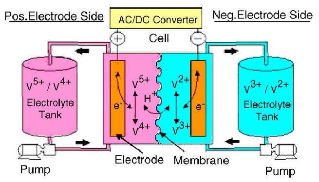
Copyright Declaration

The copyright of this thesis belongs to the author under the terms of the United Kingdom
Copyright   Act   as   qualified   by   University   of     Strathclyde   Regulation   3.50.   Due
acknowledgement must always be made of the use of any of the material contained in, or
derived from, this thesis.

Eric Francisco                                                                                   2

Energy Buffering for large wind farms                     MSc Energy Systems & the Environment

ABSTRACT

Storage technologies are essential if the renewables penetration level, into electricity
generation, is to increase. This project aims to define an appropriate form of electricity
storage, for regulating the output of a large wind farm, and carries out a cost analysis of the
chosen storage. An intensive literature review, on storage for power systems, found that flow
batteries, such as all vanadium redox energy storage system (VRB-ESS), are the most
suitable technologies. They allow high input/output power for longer periods than other
advanced batteries and, contrary to hydro pumped and compressed air energy storage,
VRB-ESS batteries do not need any specific site requirements.

This project assessed different battery storage operating strategies in relation to the
operation of the British electricity market. Data, from the Braes of Doune wind farm, was
used to test three scenarios that were developed to incorporate the batteries into a wind
farm. The first scenario was to smooth the output of the wind farm so as to give a constant
power output every thirty minutes. The second scenario involved smoothing the wind farm
output to give a constant power output every four hours. The final scenario investigated
delivering power mainly during peak-time periods. In order to assess the functioning of the
batteries, these scenarios were simulated with two different control systems: the first one
runs simultaneously with the wind farm output and regulates it; the second one delivers a
constant power based only on the energy available in the storage device. For each one of
these configurations, the necessary size of the battery was set up. Considering the additional
revenue given for providing constant power, a cost analysis was carried out to define which
configurations were cost-beneficial by the end of the project lifetime.

Taking into account the shortest period of time and using the simultaneous control system
gave the best results. It was shown that the storage system has a break-even point after 30
years and considering that a wind farms’ lifetime is 25 years, this configuration is not viable
yet. Therefore the initial cost of the battery has to be reduced or the additional revenue
increased in order to expand the use of VRB-ESS flow batteries for buffering wind farms’
output.

Eric Francisco                                                                               3

Energy Buffering for large wind farms                 MSc Energy Systems & the Environment
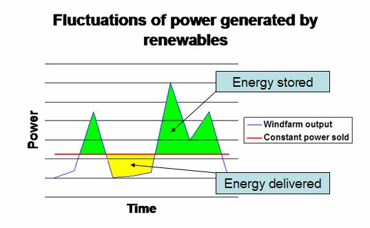
TABLE OF CONTENTS

A.        INTRODUCTION :.................................................................................................... 11

B.        BACKGROUND OF THE PROJECT ........................................................................ 13

     1.   A real need for storage: ......................................................................................... 14

1.1.            Intermittency: unavoidable drawback of renewables......................................... 14
1.2.            Costs of intermittency. ...................................................................................... 16

     2.   Storage methods:................................................................................................... 17

2.1.            Lead acid batteries: .......................................................................................... 17
2.2.            Advanced batteries:.......................................................................................... 19
2.3.            Electrostatic storage: capacitors: ...................................................................... 20
2.4.            Mechanic storage: flywheels:............................................................................ 21
2.5.            Hydraulic storage: pumped storage: ................................................................. 21
2.6.            Pneumatic storage: compressed air: ................................................................ 21
2.7.            Magnetic storage: magnetic superconductors:.................................................. 22
2.8.            Hydrogen:......................................................................................................... 22

     3.   The VRB-ESS technology:..................................................................................... 23

3.1.            The Technology:............................................................................................... 23
3.2.            VRB-ESS compared to other storage technologies: ......................................... 26

     4.   Brief presentation of the British electricity market :............................................ 28

4.1.            The balancing mechanism:............................................................................... 30
4.2.            Imbalances and settlements: ............................................................................ 30
4.3.            Sell price profile:............................................................................................... 30

     5.   Detailed description of the project : ..................................................................... 34

C.        SCENARIOS AND CONTROL SYSTEMS: .............................................................. 35

     1.   Choice of the scenarios:........................................................................................ 36

1.1.            Delivering energy mainly during peak-time period: ........................................... 36
1.2.            Delivering a constant power for each block (4 hours): ...................................... 36

Eric Francisco                                                                                                                     4

Energy Buffering for large wind farms                                    MSc Energy Systems & the Environment
1.3. Delivering a constant power for each half hour: ................................................ 37
2. Configurations of control systems: ...................................................................... 39
2.1. Simultaneous control: ....................................................................................... 39
2.2. Two associated controls: .................................................................................. 40
3. Algorithms of both control systems:.................................................................... 42
3.1. Simultaneous control: ....................................................................................... 42
3.2. Two associated controls: .................................................................................. 47
D. PARAMETERS OF THE ANALYSIS: ....................................................................... 51
1. Presentation of the wind farm output data:.......................................................... 51
1.1. Rough data:...................................................................................................... 51
1.2. Data characterisation:....................................................................................... 52
2. Prediction of the output power of the wind farm: ................................................ 53
2.1. The prediction: an important parameter. ........................................................... 54
2.2. Prediction based on the previous values: ......................................................... 55
2.3. Prediction based on the previous values and the energy stored: ...................... 57
2.4. Prediction based on the changing rate: ............................................................ 59
2.5. Comparison between the three previous methods and conclusion: .................. 60
2.6. Ideal prediction: ................................................................................................ 61
2.7. Peak-time model: ............................................................................................. 62
2.8. Matrix of configurations: ................................................................................... 63
3. Characteristics of the flow batteries:.................................................................... 64
3.1. Sizing the battery:............................................................................................. 64
3.2. Establishing the cost of the battery: .................................................................. 66
4. Financial analysis parameters: ............................................................................. 68
4.1. Calculation of the Net Present Cost (NPC): ...................................................... 68
4.2. Calculation of the Break-Even: ......................................................................... 72
4.3. Optimisation process: ....................................................................................... 73
Eric Francisco 5
Energy Buffering for large wind farms MSc Energy Systems & the EnvironmentE. RESULTS AND ANALYSIS...................................................................................... 74
1. Initial results:.......................................................................................................... 74
1.1. Detailed results of the simultaneous control for the block scenario: .................. 74
1.2. Results and analysis of the configurations with simultaneous control: .............. 76
1.3. Results and analysis of the configurations with associated controls: ................ 78
2. Results after optimisation: .................................................................................... 79
2.1. Optimisation process: ....................................................................................... 79
2.2. Results of all the simultaneous control configurations:...................................... 79
2.3. Analysis of the results:...................................................................................... 79
3. Limitation of the power rating:.............................................................................. 82
3.1. New results: ..................................................................................................... 82
3.2. Analysis:........................................................................................................... 83
3.3. Limitation of the associated control system configuration: ................................ 83
4. Influence of the main parameter: .......................................................................... 85
4.1. the additional revenue given for delivering the constant power:........................ 85
4.2. Results: ............................................................................................................ 86
5. Final results and recommendations: .................................................................... 89
5.1. Costs of the batteries for each configuration:.................................................... 89
5.2. Final NPC and break-even for the most suitable configuration: ........................ 91
F. CONCLUSION ......................................................................................................... 92
Eric Francisco 6
Energy Buffering for large wind farms MSc Energy Systems & the EnvironmentCONTENTS OF FIGURES Figure 1 - Magnitude of wind power hourly changes [1] ....................................................... 15 Figure 2 - Lead acid battery description [7] .......................................................................... 17 Figure 3: Schematic of the VRB-ESS battery [2].................................................................. 24 Figure 4 - charge-discharge curve of a VRB battery [2] ....................................................... 24 Figure 5: Discharge time at rated power VS system power rating [13] ................................. 27 Figure 6: Overview of BETTA [14] ....................................................................................... 29 Figure 7: Variation of the SSP along the day [15] ................................................................ 31 Figure 8: Variation of SSP along the previous years [15] ..................................................... 32 Figure 9: Variation of the SSP along last year [15]............................................................... 33 Figure 10: Map of Scotland – location of the wind farm........................................................ 35 Figure 11: Configurations of power delivered....................................................................... 38 Figure 12: Illustration of the simultaneous control ................................................................ 39 Figure 13: Illustration of the separated control systems ....................................................... 41 Figure 14: Algorithm of the simultaneous control system ..................................................... 45 Figure 15: Algorithm of the two associated controllers ......................................................... 49 Figure 16: Variation of the wind farm output on the 30th April 2006 ..................................... 52 Figure 17: Monthly energy delivered by the wind farm ......................................................... 53 Eric Francisco 7 Energy Buffering for large wind farms MSc Energy Systems & the Environment
Figure 18: Importance of the predicted power...................................................................... 54

Figure 19: Algorithm for prediction of the wind farm output based on the previous values ... 55

Figure 20: Influence of the period of time for the prediction based on the previous values... 56

Figure 21: Algorithm for prediction of the wind farm output based on the previous values and
the battery energy content ................................................................................................... 57

Figure 22: Influence of the period of time for the prediction based on the previous values and
the energy content of the battery ......................................................................................... 58

Figure 23: Algorithm for prediction of the wind farm output based on the changing rate ...... 59

Figure 24: Influence of the period of time for the prediction based on the changing rate...... 60

Figure 25: Perfect prediction - performance indicator VS capacity of the battery ................. 61

Figure 26: Algorithm for prediction of the wind farm output on peak time periods ................ 62

Figure 27: Improved algorithm for prediction of the wind farm output on peak time periods . 63

Figure 28: Algorithm to estimate the initial size of the battery .............................................. 65

Figure 29: Variation of the costs of the battery for the block configuration ........................... 67

Figure 30: Results of the battery on the wind farm output before optimisation ..................... 75

Figure 31: Influence of the size of the battery on the performance and the cost of the system
............................................................................................................................................ 77

Figure 32: Impact of the optimisation on the energy capacities............................................ 80

Figure 33: Impact of the optimisation on the cell stack sizes................................................ 80

Figure 34: Impact of the optimisation on the NPC................................................................ 81

Figure 35: Impact of the limitation of the power rating on the NPC....................................... 83

Eric Francisco                                                                                                                               8

Energy Buffering for large wind farms                                           MSc Energy Systems & the Environment
Figure 36: Direct impact of limiting the rate power for the associated control configurations 84

Figure 37: Impact of the rated power on the associated control configurations .................... 85

Figure 38: Impact of the additional revenue on the NPC...................................................... 87

Figure 39: Additional revenue necessary to make the project cost effective ........................ 88

Figure 40: Viable costs of the batteries ................................................................................ 89

Figure 41: Costs of the batteries per kWh of energy delivered during the project lifetime .... 90

Figure 42: Variation of the NPC for the output smoothing with perfect prediction................. 91

Eric Francisco                                                                                                            9

Energy Buffering for large wind farms                                MSc Energy Systems & the Environment
CONTENTS OF TABLES

Table 1 - Causes and Time scale of wind variation [5]. ........................................................ 14

Table 2 - Time characteristics required for storage applications [1]...................................... 16

Table 3: Characteristics of Hydrogen storage [11] ............................................................... 23

Table 4: Applications of the different storage technologies .................................................. 26

Table 5: Variation of the SSP block per block ...................................................................... 31

Table 6: Comparison between the wind farm output prediction methods ............................. 60

Table 7: Matrix of configurations .......................................................................................... 64

Table 8: Initial capacities of the battery................................................................................ 65

Table 9: Results from the simultaneous control for the block configuration .......................... 74

Table 10: Results for simultaneous control before optimisation ........................................... 76

Table 11: Results for associated controls before optimisation.............................................. 78

Table 12: Results for simultaneous control after optimisation .............................................. 79

Table 13: Excess of energy needed to limit the power rating ............................................... 82

Eric Francisco                                                                                                             10

Energy Buffering for large wind farms                                  MSc Energy Systems & the Environment
A. INTRODUCTION :

Renewables, and especially wind power, have achieved a significant level of penetration in
the British power generation market in recent years and are supposed to reach the target of
20% by 2020. It can be anticipated that they will make increasing contributions to electricity
generation in the near future. However, renewable energy production is intermittent and
matching the supply and the demand is often a problem. This is a barrier to their extensive
use.

Most renewables are tied to strong grids where the base load power plants (generated by
hydro-electric, coal or nuclear) minimise quality concerns and make it less important for wind
generation to be matched to consumption. According to experts, renewables’ generation up
to 20-30% of overall electricity generation should not destabilise the grid. In isolated electrical
grids such as islands which are not linked to strong grids, renewables’ generation can be
very destabilising for the grid, with dramatic consequences for the quality of the power
delivered. Indeed, for both of these cases, reducing greenhouse gas emissions for a
sustainable and clean future is achieved at the expense of grid planning and predictability.
The main solution to this problem is storage. Indeed, it can provide output stability, ramping
control, but can also guarantee power generation when there is no natural resource (sun,
wind, wave…) [1]; a storage component will allow renewables to achieve a high penetration
into the grid.

Eric Francisco                                                                                  11

Energy Buffering for large wind farms                  MSc Energy Systems & the Environment
Unfortunately, direct storage of electricity is not possible. Research and development of
economical and efficient storage systems is currently being carried out [2]. Of all the new
energy storage technologies, the redox (reduction/oxidation reaction) flow battery appears to
offer great promise as a low cost and high-efficiency large scale energy storage system. This
storage system is able to deliver several MW over a period of several hours. Based on these
attractive features, the main objective of this project is to find out if this technology is suitable
for regulating the output of wind farms. This project aims to assess different operating
strategies in relation to the operation of the British electricity market.

Redox flow batteries are currently used in a few wind farms to smooth out their output. For
example, Tomamae Wind Villa, the biggest wind farm in Japan has been using it for a few
years in order to smooth out the power delivered to the grid and to give a constant value
every twenty minutes. In Australia, the King Island wind farm has also been using it to give
their system support in order to enable them to run a higher wind penetration knowing that
the battery would give short term support in case of a rapid load increase [3]. This project is
different from the ones above because it aims at tackling a different objective: studying the
feasibility of considering redox flow batteries to smooth out the output power of a wind farm
for longer periods and check if this solution is economically viable. This will be done by using
a time step simulation to assess the size of the battery necessary for a large wind farm and
then its performance.

In order to run accurate simulations, this project will be based on real data: the output power
of a wind farm (Braes of Doune) located in Scotland near Dunblane, and generates up to 98
megawatts from 49 turbines. The main manufacturer of redox flow batteries: VRB-ESS
based in Canada provided the technical characteristics of the equipment. From this data,
different scenarios (using simulation) were studied in order to define the most suitable one
for the wind farm considered, following this an economical feasibility study was carried out.

Eric Francisco                                                                                    12

Energy Buffering for large wind farms                   MSc Energy Systems & the Environment
B. BACKGROUND OF THE PROJECT

Energy storage is unavoidable if we want to increase the penetration level of intermittent
power sources such as renewables [4] or generally to match the demand with the supply.
Indeed, the demand for electricity from consumers (domestic and industrial) is constantly
changing within the following time scales:

                     -   Minutes and hours: due to individuals’ and industries’ actions;
                     -   Daily: due to the peak time consumption period;
                     -   Weekly: due to the fact that industries are closed on weekends;
                     -   Seasonal: winter require more lighting and heating.

To cope with this changing demand, additional power plants can be brought online such as
combustion gas turbines, spinning reserves can be connected; or stored energy can be
released. Since direct storage of electricity is not possible, energy must be stored by indirect
ways instead [4]:

                     -   electro-chemically (batteries, fuel cells),
                     -   mechanically (flywheels),
                     -   electrostatically (capacitors),
                     -   magnetically (magnetic superconductors),
                     -   hydraulically (pumped storage),
                     -   pneumatically (compressed air),
                     -   producing hydrogen.

Ideally, the perfect storage would require little space (high energy density) and would be able
to deliver the energy stored under full control (rapidly or slowly). It should be safe, affordable
and require little maintenance. It should operate on a reversible charge/discharge cycle with
a long cycle life, and be capable of deep discharge without reducing its lifetime.

Currently, there is no equipment that can meet all these requirements and this reduces the
potential of renewables to challenge the use of fossil fuels. As mentioned before, variability is
the main barrier to the development of renewables. In the following paragraph, the needs for
storage will be explained in more detail in order to understand the importance of storage
technologies.

Eric Francisco                                                                                 13

Energy Buffering for large wind farms                  MSc Energy Systems & the Environment
1. A real need for storage:
1.1. Intermittency: unavoidable drawback of renewables
Since renewables use fluctuating sources of energy (wind, solar, wave…) their output power
cannot be constant. This is due to the nature itself of these sources of energy. For example,
wind turbine output variations are due to several causes on different time scales. The
following table gives a summary:
Causes of variation Time scale of variation
Wind gusts (turbulence) Short term seconds
Normal wind speed variations Minutes
Inversion layers Hourly
Diurnal cycle Daily
Changing (long term) wind patterns Days
Seasonal cycle Monthly
Annual variation Yearly
Table 1 - Causes and Time scale of wind variation [5].
Eric Francisco 14
Energy Buffering for large wind farms MSc Energy Systems & the EnvironmentThe following chart represents the magnitude of wind power changes. It can be seen that it
can reach until 1000% annually, and 100% monthly.
Figure 1 - Magnitude of wind power hourly changes [1]
In order to save all the energy recoverable and to sell it when needed (peak time period daily
or during winter annually) or constantly (by minimising the fluctuations), a good storage
system has to be considered to improve a wind farms output. Indeed, many benefits can be
brought by storage applications considering several time scales. Table 2 shows the
advantages that can be brought by storing energy within different periods.
Period of storage Task – improvements
0.02 – 0.2s Improvement of stability
0.12 – 0.2s Countermeasure against supply disruption
Eric Francisco 15
Energy Buffering for large wind farms MSc Energy Systems & the EnvironmentFew seconds Output smoothing
0.5 – 120s Voltage stabilisation, frequency regulation
30 – 300s Spinning reserve
180 – 10000s Peak shaving
Daily 4 – 12h Load levelling
Weekly 40 – 60h
Seasonal 3 months
Table 2 - Time characteristics required for storage applications [1].
1.2. Costs of intermittency.
We can say that energy storage is economical when the marginal cost of electricity is higher
than the costs of storing and retrieving the energy plus the price of the energy lost in the
process. Indeed, all these costs have to be considered in order to accept the installation of a
storage system [6].
Concerning renewables, renewable electricity is sold cheaper than controllable power from
conventional sources due to the varying nature of the output. As renewable supplies become
increasingly popular, this difference in price creates an increasingly large economic
opportunity for grid energy storage.
An in-depth analysis has to be carried out to estimate the marginal cost of electricity in this
case for different scenarios as the price of electricity varies with its quality and length of
constant period delivered. More details about the British electricity market will be given later.
Eric Francisco 16
Energy Buffering for large wind farms MSc Energy Systems & the EnvironmentIn order to validate the choice of flow batteries, their characteristics and those of other
storage technologies are described and then compared.
2. Storage methods:
2.1. Lead acid batteries:
Lead-acid batteries are very common in many applications. They are the oldest chemical
storage device. Because they are used so widely, the manufacturing cost is very low (£150-
300/kWh) [7].They are used in cars but also as a back-up power supply for electricity needs.
Figure 2 represents the operation of a lead-acid battery.
Figure 2 - Lead acid battery description [7]
The battery consists of pairs of plate, one lead ad the other lead coated with lead dioxide.
Both are immersed in a dilute solution of sulphuric acid which is the electrolyte. During the
discharge mode the cathode is positive and the anode negative; both electrodes are
converted into lead sulphate. Charging restores the positive electrode to lead dioxide and the
negative one to metallic lead [8].
Eric Francisco 17
Energy Buffering for large wind farms MSc Energy Systems & the EnvironmentLead-acid batteries are sized in Ampere-hours. To increase the amp-hour rating, it is
necessary to add more batteries – the current rating is tied to the amp-hour rating. This way
of storing energy is very convenient for short duration applications (less than one hour). Its
characteristics are summarised here:
• Battery lifetime:
The battery lifetime is defined for 5, 10 or 20 years [9]. If fully discharged, there is a life
degradation curve because of the irreversible physical changes in the electrodes, so the
battery will have a reduced life. Basically, using a 5 year lifetime battery regularly, leads to
only 3 years of use. Usually, the ultimate failure occurs between several hundred and 2000
cycles [8].
• Depth of discharge (DoD):
Maximum DoD of 30% without damaging the battery and shortening the life of the battery [9].
It is impossible to measure State of charge (SoC) accurately without taking it off line [7].
• Recharging rate:
The battery may be recharged at any rate that does not produce excessive gassing,
overcharge or high temperature. A discharged battery may be recharged at a high current
initially. However, as the battery approaches its full charge the current must be decreased to
reduce gassing and excessive overcharging. It takes 5 times as long to recharge a lead acid
battery to the same charge capacity as it does to discharge it. For a 4 hours discharge the
full capacity is only available after 20 hours, so in any given 24 hours period, you can only
get one complete discharge [9].
• Sizing the battery:
Usable energy density for storage applications is only about 12Wh/litre [9].
• Costs and maintenance:
The disposal cost is estimated between 500 and 1500$/kWh. Maintenance costs around
$0.02/kWh [9].
Eric Francisco 18
Energy Buffering for large wind farms MSc Energy Systems & the Environment2.2. Advanced batteries: The main advantage of advanced batteries is that they offer higher energy densities than lead-acid batteries. At the moment, they are not used so widely and therefore, are much more expensive. They are used for the same applications: power quality and back-up at manufacturing plants, electronic devices and cars. They also offer a longer life time and specific characteristics as detailed below: • Nickel-cadmium : Ni-Cad batteries, while more expensive initially, have a lifetime over double than of lead-acid batteries (up to 3500 cycles at 85% depth of discharge [7]). In stationary applications where reliability is important, these are used in standby applications. Because they require no attention, stand high temperatures and are environmentally tolerant, they can be installed in remote locations and virtually forgotten due to their very low maintenance requirements. Their main disadvantages, apart from cost ($0.80/Wh) [7], include the high cost of post-life toxic disposal and a limited global reserve of cadmium. • Lithium ion : As they have a nigh energy density (200Wh/kg of lithium) [7], Lithium-ion batteries are light and provide a high voltage (about 4V per cell) [7]. They almost have a 100% efficiency and a long lifecycle - about 3000 cycles at 80% depth of discharge. With lithium being the lightest solid element (0.534 g·cm−3) [7], Lithium ion batteries based on it can be much lighter than conventional types and therefore, very handy for portable application. However, moving up to large scale creates difficulties regarding safety aspects, in particular the high cost of containing the reactivity of lithium and electrode assembly. • Sodium-sulphur or high temperature battery: These batteries are attractive for large storage system. Contrary to most electro-chemical systems, in a sodium-sulphur cell the electrodes are liquid (molten sodium for the cathode and molten sulphur for the anode) and the electrolyte solid, made of alumina ceramic. The assembly has to be kept at 300-350°C to remain active materials liquid [10]. A reversible Eric Francisco 19 Energy Buffering for large wind farms MSc Energy Systems & the Environment
reaction (sodium + sulphur = sodium sulphide) yields electrons in an external circuit which
generate a potential difference of 2V per cell [7]. However, even if this technology is very
promising, its cost is still too high to implement it into large scale applications.

    •   Metal-air :

Potentially the cheapest batteries are metal-air types. Anodes of commonly available metals
(zinc, aluminium, lead and even iron) placed in a liquid or polymer impregnated electrolyte of
potassium or other conducting hydroxide, release electrons during the ensuing oxidation
reaction. These, attracted towards the carbon plus catalyst cathode when flowing in an
external circuit, create a potential drop at the battery terminals. Metal-air batteries are
inherently safe and environmentally benign. They have a high energy density (until
13kWh/kg) [7]. But while high energy, controllable discharge and low cost could suit them to
many primary battery applications, the only known big rechargeable unit available so far (a
zinc-air system) has a very short lifecycle and a charge/discharge efficiency of about 50%
only [4].

    2.3. Electrostatic storage: capacitors:

Capacitors are another option for storage, especially super and ultracapacitors. Energy is
stored in the form of an electrostatic field. This technology offers extremely fast charge and
discharge capability, even if they have a lower energy density than batteries, they can be
cycled tens of thousands of times. Supercapacitors store energy in an electric double layer
formed between each of two electrodes and the ions existing in the electrolyte. The distance
over which the charge separation occurs is just a few angstroms. Capacitance and energy
density are thousands of times greater than for conventional electrolytic capacitors. By now,
power ratings of around 100kW are feasible, with energy being delivered in anything from
one second to a minute [4].

Electrolytes can be either aqueous or organic. The higher energy density available with
organic electrolytes can be boosted further by using metal for one of the electrodes, rather
than the porous carbon commonly used. Response times down to milliseconds are possible.

Eric Francisco                                                                             20

Energy Buffering for large wind farms                   MSc Energy Systems & the Environment
2.4. Mechanic storage: flywheels: Energy is stored in the rotating mass of a flywheel. The energy stored is released when the cylinder reduces its speed which can be controlled in order to be used as back-up systems for low power or short term applications. The rotating mass stores the short energy input so that rotation can In order to minimize aerodynamic losses flywheels are placed in a vacuum enclosure and the use of superconducting electromagnetic bearings can virtually eliminate energy losses caused by friction. The efficiency of the system is estimated at 90%. With the ability of flywheels to store high amounts of energy and respond rapidly, they could smooth out these short and medium-term variations. However, they cannot compensate for long period power intermittencies of wind farms for example. Cost, in the present stage of evolution is an issue, as 250kW units cost around £50,000. A compensating factor is the high lifecycle. Indeed, the predicted life is over 10 million cycles (some 15-20 years in high frequency renewables use) minimal attention is needed. Future flywheels (under development) of up to 1.5MW spinning at 60,000rev/min or more are envisaged, with discharge times of up to 15 minutes [4]. 2.5. Hydraulic storage: pumped storage: Pumped hydro energy storage consists in storing water in a vessel in a high elevation, and then releasing it into a lower vessel through a turbine when power is needed (peak time). When there is no demand (off-peak time), the water is pumped back to the upper vessel. This way electricity can be stored indefinitely and in large quantities with a good efficiency (80%) [8]. It is the only large power system technique widely used to create seasonal storage. This system as it allows big energy storage can be used to smooth out the demand for base load power plants (can be switched on within few minutes). However, this is extremely site specific, has a considerable environmental impact, and is normally used at large scale because of the big investment that it represents. By now, over 90GW of pumped storage (associated with dams) is available worldwide [4]. 2.6. Pneumatic storage: compressed air: During the off-peak periods, air is compressed by an electrically powered turbo-compressor in big underground storage reservoirs such as a cavern or an abandoned mine. Later, when Eric Francisco 21 Energy Buffering for large wind farms MSc Energy Systems & the Environment
energy is needed, expansion is achieved with a natural-gas powered heater which drives a
combustion turbine and then produces electricity back. This system is usually used on a daily
cycle, charging at night (off-peak time) and discharging during the day. Small-scale
installations used as energy stores for wind farms could add value by enabling the power to
be sold at peak demand times; they are still under development [4].

   2.7. Magnetic storage: magnetic superconductors:

Superconducting magnetic energy storage (SMES) stores energy in the magnetic field
created by the flow of direct current through a coil that has been super-cooled by a
refrigerator (possibly cryogenic systems). SMES loses the least amount of electricity in the
energy storage process compared to other methods of storing energy. Indeed, once the
superconducting coil is charged, the current will not decay and the magnetic energy can be
stored indefinitely. They are highly efficient; the round-trip efficiency is greater than 95%,
however, even if they can provide power almost instantaneously, they can only deliver a high
power during a brief period. The loss of efficiency is due to the energy consumed by the
cooling system [8]. If SMES were to be used for utilities it would be a diurnal storage device,
charged from base load power at night and meeting peak loads during the day. By now,
several 1MW units are used for power quality control in installations around the world,
especially to provide power quality at manufacturing plants requiring ultra-clean power. Using
them to smooth out the power output of a wind farm should be then considered. Considering
their short time power issues, they cannot be used as back-up power supply. Equipments
with a 20MWh capacity are still under development [4].

   2.8. Hydrogen:

Hydrogen storage can respond to the fluctuations in energy production from renewables on a
short term (hourly) or longer term (seasonally). The power generated from renewables (wind
or solar power) can be used to produce hydrogen by water electrolysis [11]. This process has
a good efficiency (>70%), but it is also expensive (large-scale production cost is £2.5-
4.0/GJ). The hydrogen produced can be stored as a solid, a liquid or a gas.

Eric Francisco                                                                              22

Energy Buffering for large wind farms                MSc Energy Systems & the Environment
Gaseous H2 Storage Liquid H2 Storage               Solid H2 Storage
                                                                                Developing
  Current status          Available technology   Available technology
                                                                                technology
                                                                              Metal hydrides
                                                                             (potential for > 8
                          C-fibre composite       Cryogenic insulated
                                                                             wt.% H2 and > 90
 Technology used        vessels (6-10 wt% H2      tank (ca. 20 wt% H2
                                                                             kg/m3 H2-storage
                           at 350-700 bar).      at 1 bar and -253°C).
                                                                            capacities at 10-60
                                                                                   bar).
                       Table 3: Characteristics of Hydrogen storage [11]

When energy is needed, hydrogen is then transformed back into electricity. Therefore, it is
much better to use this way of storing energy when hydrogen itself is needed as a source of
energy (e.g. fuel for transportation). The whole process including the water electrolysis and
turning the hydrogen into electricity is far too expensive for the moment.

3. The VRB-ESS technology:

   3.1. The Technology:

Redox flow batteries like VRB-ESS are more and more used to store energy for renewables.
The electrolyte (liquid vanadium for VRB-ESS) is stored externally and is pumped to the cell
stack as the energy is needed. The main advantage of VRB-ESS system is that the storage
capacity can be increased by raising the electrolyte volume and the power output by
increasing the number of cell stacks. The main drawback is that the energy density of the
electrolyte used is low compared to other batteries, therefore, big storage capacities have to
be used. The characteristics of VRB-ESS flow batteries are detailed below [9]:

   •   Principle of VRB

As shown in figure 3, the VRB has two electrolyte loops both containing vanadium in
sulphuric acid medium, but in different valence states which may be oxidized/reduced at the
electrodes. The vanadium redox pairs are V2+/V3+ and V4+/V5+ for negative and positive
halves of the cell, respectively. The electrical balance is achieved by the transport of
hydrogen ions in the electrolytes across the membrane during operation of the cell.

Eric Francisco                                                                               23

Energy Buffering for large wind farms                 MSc Energy Systems & the Environment
Figure 3: Schematic of the VRB-ESS battery [2]
• Battery lifetime:
The lifetime of this battery is measured in cycles (until 10,000 cycles) that should exceed 10
years. At the end of the lifetime, only the membrane of the cell stacks has to be changed.
The lifetime of the electrolyte is indefinite. This lifetime is independent of the rate of
discharge, depth of discharge and can be slightly influenced by the temperature. The
following chart shows the charge-discharge cyclic curves:
Figure 4 - charge-discharge curve of a VRB battery [2]
• Depth of discharge (DoD):
From 80% to 20% state of charge (During each cycle, it can be discharged to 20% and
recharged to 80% indefinitely) thus 60% usable range.
Eric Francisco 24
Energy Buffering for large wind farms MSc Energy Systems & the Environment• Discharge rate: Can be discharged at any rate even at 5 times it nominal rating for up to a minute without any impact on its performance or reduction in its life. • State of charge (SoC): Very low to zero self discharge. Besides, on the cell-stack an indicator gives an accurate level of charge. • Recharging rate: VRB-ESS charges theoretically over a one-to-one time duration, but practically over a 1.8:1 time duration. • Sizing: The system can be easily upgraded, indeed additional storage capacity can be added by increasing the volume of electrolyte (1kWh=70litres) and output power can be increased by adding cell stacks. • Operations and Maintenance: Low operating temperatures and low sensitivity to ambient temperature variations allow easier and cheaper maintenance - Very low maintenance costs ($0.003/kWh). PCS is used for the control of the whole system. Once the signals of charge and discharge, ramp rates and response times are given to the controller it manages the system. For MW size batteries, the PCS costs $150/kW until 2MW. • Environmental aspect: Using flow batteries contributes between 7% and 25% of emissions reductions of major polluting gases (CO2, SO2, CO, CH4, NOx) during their lifecycle when compared to lead- acid batteries. Eric Francisco 25 Energy Buffering for large wind farms MSc Energy Systems & the Environment
3.2. VRB-ESS compared to other storage technologies:

From the previous descriptions, the following table summarises the main advantages and
disadvantages of various storage technologies:

 Storage technology        Main advantages        Main disadvantages             Applications
Lead acid batteries     Low capital cost.        Limited lifecycle        Short term storage.
                                                 when deeply
                                                 discharged,
                                                 Low efficiency.
Advanced batteries      High power and           High production cost,    Short and medium
                        energy densities,        High cost of post life   term storage in
                        High efficiency,         toxic disposal,          remote locations.
                        Low maintenance.
Metal – air batteries   Very high energy         Very short lifecycle,    Long term storage
                        density.                 Low efficiency.          only, which can be in
                                                                          remote locations.
Capacitors              Long lifecycle life,     Low energy density.      Very short term
                        High efficiency.                                  storage.
Flywheels               High power,              Low energy density.      Low-power
                        Very durable,                                     applications or short
                        Low maintenance.                                  term power quality
                                                                          support.
Pumped storage          High capacity,           Special site             Emergency power
          &             Low cost.                requirements.            injection to the grid,
Compressed air                                   Serious ecological       Smoothing out the
energy storage                                   impact.                  demand for base
(CAES)                                                                    load generation.
Superconducting         High power.              High production cost     Power quality
magnetic energy                                                           improvement,
storage (SMES)                                                            Short term back-up
                                                                          power supply.
Hydrogen storage        High energy density,     Low efficiency of the    Long term storage,
                        low maintenance,         overall cycle:           stand-alone power
                        high storage             electricity – hydrogen   systems, transport.
                        efficiency.              – electricity
                                                 High capital cost
Flow batteries          High capacity,           Low energy density       Short and long term
                        Independent power                                 storage.
                        and energy ratings.
                   Table 4: Applications of the different storage technologies

Eric Francisco                                                                                  26

Energy Buffering for large wind farms                 MSc Energy Systems & the Environment
According their characteristics, storage technologies can also be visualised on the following
graph which represents the most suitable storage for each configuration: rating power and
the discharge time at rated power.
Figure 5: Discharge time at rated power VS system power rating [13]
Taking into account that wind farms considered in this project have an average power rating
between 5 and 30MW, and that there is a need to store energy for different range of time
going from minutes until hours, the flow batteries are definitely the technology to consider for
this project. Their input power can be up to 100MW, which is the maximum size of the cell
stacks, and it is possible to increase their energy capacity just by adding some electrolyte.
Only pumped hydro and compressed air technologies could provide the same rated power,
but they need special site requirement and cannot provide storage for short term
applications. They are used only to deliver power for a long period, indeed, regarding the
CAES, turning on combustion turbines cannot be considered for a few minutes. The aim of
Eric Francisco 27
Energy Buffering for large wind farms MSc Energy Systems & the Environmentthis project is to come up with a storage that could be used for most of renewables, therefore not only those located in special sites. In order to adjust this project to the British market, the following section provides more details about how it works and how it has to be considered for this project in order to have greater benefits from the battery. 4. Brief presentation of the British electricity market : The BETTA (British Electricity Trading and Transmission Arrangements) are based on the principle that electricity is traded between suppliers and consumers at prices which they have both agreed on. They include the arrangements needed to provide a mechanism for clearing and settling the imbalances that may occur between the prediction of supply or demand and the actual position. This part of the process is called imbalance settlement; it ensures that the overall system stays in balance in real time. The following diagram shows all the arrangements made by the BETTA: Eric Francisco 28 Energy Buffering for large wind farms MSc Energy Systems & the Environment
Figure 6: Overview of BETTA [14]

The gate closure is the moment when market participants (generators, suppliers, traders and
consumers) notify the system operator of their intended final position and is set at one hour
ahead of delivery. Afterwards, no further contract notification can be made. By contracting on
ETSA (Electricity Trading Service Arrangements), the generators take the imbalancing risk.
This means that if they do not supply the amount of energy predicted they have to pay
penalties. On the other hand, if the production is higher than the prediction, the excess will
only be bought at SSP (System Sell Price). This price is determined by the grid every thirty
minutes. Obviously, as the supplier takes the risk of imbalance in order to assure a quantity
of electricity, this amount of energy will be sold more expensively. For the generators, this is
the main advantage of contracting on ETSA. The same process occurs for customers with
large electricity requirements who contract on ETSA. Electricity consumed without any
contract will be bought at SBP (System Buy Price) which also changes every thirty minutes.

Eric Francisco                                                                               29

Energy Buffering for large wind farms                MSc Energy Systems & the Environment
4.1. The balancing mechanism:

Participation in the balancing mechanism involves submitting offers (proposed trades to
increase the generation or decrease the demand) and/or bids (proposed trades to decrease
the generation or increase the demand). This mechanism operates on a ‘pay as bid’ basis.
As mentioned before, the price of electricity is mentioned within the bid and is then
immediately paid.

National Grid purchases offers, bids and other balancing services to match supply and
demand, resolve transmission constraints and thereby balance the system. As the market
moves towards the delivery time, National Grid needs to be able to assess the physical
position of all the market participants to ensure the security of supply. Before the gate
closure each one of them has to supply a final physical notification.

   4.2. Imbalances and settlements:

The magnitude of any imbalance between participants’ contractual positions (as notified at
gate closure) including accepted offers and bids, and the actual physical flow between
suppliers and demanders is determined. The resulting energy imbalance is then settled at
the cash out price calculated by the settlement administrator which can be a company such
as Elexon in the UK.

As mentioned before, the system sell price (SSP) is paid to parties with a surplus and without
a contract. Parties with a deficit will be charged at the system buy price (SBP). These prices
are designed to reflect the cost of operating the balancing mechanism or purchasing short
term energy ahead of gate closure in the forward and spot markets. In the case of an
unpredicted output power, such as the one from renewables, this is how electricity is bought.

These incremental costs are derived by taking the average cost of the marginal 100MWh [14]
of actions that the National Grid has taken to resolve the energy imbalance.

   4.3. Sell price profile:

The System Sell Price is a good indicator of the evolution electricity prices. Indeed, as supply
contracted on ETSA is bought more expensively than SSP, it has to follow its evolution.

Eric Francisco                                                                               30

Energy Buffering for large wind farms                 MSc Energy Systems & the Environment
Therefore, from the data provided by Elexon (a settlement administrator), the following
graphs were plotted:

                                                           Average SSP variation along the day

                       45.00

                       40.00

                       35.00

                       30.00
 Average SSP (£/MWh)

                       25.00

                       20.00

                       15.00

                       10.00

                        5.00

                        0.00
                            0:00   2:00   4:00      6:00   8:00     10:00    12:00    14:00      16:00   18:00   20:00   22:00
                                                                             time

                                             Figure 7: Variation of the SSP along the day [15]

These prices (SSP) fluctuate every thirty minutes. Each value represents the average price
per year at the considered time. These fluctuations explain why traders divide days in trading
blocks. Indeed, each block represents 4 hours. These blocks represent the main variations of
the SSP. The following table illustrates it:

                                                                  Average SSP (£/MWh)
                                                      block 1              18.03
                                                      block 2              18.54
                                                      block 3              28.07
                                                      block 4              27.68
                                                      block 5              32.89
                                                      block 6              22.97
                                                 Table 5: Variation of the SSP block per block

Eric Francisco                                                                                                                   31

Energy Buffering for large wind farms                                            MSc Energy Systems & the Environment
The previous values show that the best period to sell electricity is during the block 5, also
called the “peak time” period. Indeed, during this period, electricity is sold 30.3% more
expensive than the daily average SSP. For this reason, it can be really interesting for a
storing technology to save energy all day long and deliver it during these hours. On the other
hand, there is no point of selling electricity during block 1 and block 2 as the electricity is then
sold 24% less expensive than the daily average SSP.
Let us now have a look at the variation of the SSP over several years. This is plotted on the
following graph:
variation of SSP along the years
250.00
200.00
SSP prices (£/MWh)
150.00
100.00
50.00
0.00
déc-99 déc-00 déc-01 déc-02 déc-03 déc-04 déc-05 déc-06 déc-07
time
Figure 8: Variation of SSP along the previous years [15]
It can be seen on the graph that the SSP slightly increased since 2000. However, the most
important thing to notice is that the SSP always goes up during winter. It is even easier to
notice this by plotting the price over one year:
Eric Francisco 32
Energy Buffering for large wind farms MSc Energy Systems & the Environmentvariation along sept 05 - sept 06
500.00
450.00
400.00
350.00
SSP prices (£/MWh)
300.00
250.00
200.00
150.00
100.00
50.00
0.00
17-juil-05 05-sept-05 25-oct-05 14-déc-05 02-févr-06 24-mars-06 13-mai-06 02-juil-06 21-août-06 10-oct-06
time
Figure 9: Variation of the SSP along last year [15]
These prices are the average peak time system sell prices for every day. It can be seen that
they only reach and go over £50/MWh between October and March. For this reason, storage
can be considered in summer in order to deliver energy in the winter. However, this would
imply enormous reserves that cannot be reached with current storage technologies. For this
reason, in this project, such variations will not be considered.
Eric Francisco 33
Energy Buffering for large wind farms MSc Energy Systems & the Environment5. Detailed description of the project : From the previous literature review, the main objectives of the project were defined, that is to say to assess if flow batteries can be used to smooth a wind farm output and this for several periods of time. Indeed, this storage technology seems to be the most suitable one for smoothing out electricity produced by renewables. Flow batteries can accept a big power input thanks to the size of their cell stacks, and the storage capacity (expressed in kWh) is only limited by the volume of electrolyte which can be increased easily. As the storage has to consider long term applications and without any special requirement, flow batteries appear to be worth looking into. According to the British electricity market, there is a real need for good and long term predictions in order to make valuable bids which will allow selling electricity at a higher price than the SSP. Therefore, this project has assessed the different possible ways of using a flow battery for a wind farm example. Once all the configurations (scenarios and control systems) had been set up, they were simulated and then a cost analysis was carried out for each one of them. The simulation was made considering an initial size of the battery, and from that, calculated the SOC and the output of the battery. Afterwards, some recommendations are given in order to define what kind of application is the most suitable for now. Eric Francisco 34 Energy Buffering for large wind farms MSc Energy Systems & the Environment
C. SCENARIOS AND CONTROL SYSTEMS:

In this chapter, the simulation processes are detailed. They aim at simulating the behaviour
of a considered battery over a period of ten months. The objective is to calculate the SOC
and the output power of the flow battery after each step time. Regarding this, the benefit from
using the battery can be estimated and, therefore, the net present cost after the lifetime of
the project. The optimisation process used afterwards aims to minimise the net present cost
by changing the size of the battery and from this the optimum size of battery for each
configuration was defined.

In order to work on realistic scenarios, the configurations of this project have been chosen to
match the requirements of the British electricity market. From the literature review, three
main cases have appeared:

    Delivering energy mainly during peak-time
       periods;

    Delivering a constant power for each trading
       block (4 hours);

    Delivering a constant power time periods of
       half an hour.

All the simulations of this project are based on the
output power of the Braes of Doune wind farm,
between the 1st of September 2006 and the 1st of
May 2007, and include the main characteristics of
the considered flow batteries.

                                                        Figure 10: Map of Scotland – location
                                                                   of the wind farm

Eric Francisco                                                                              35

Energy Buffering for large wind farms                MSc Energy Systems & the Environment
You can also read