Self-consumption & energy storage - Energy. Anytime. Anywhere - Victron Energy
←
→
Page content transcription
If your browser does not render page correctly, please read the page content below

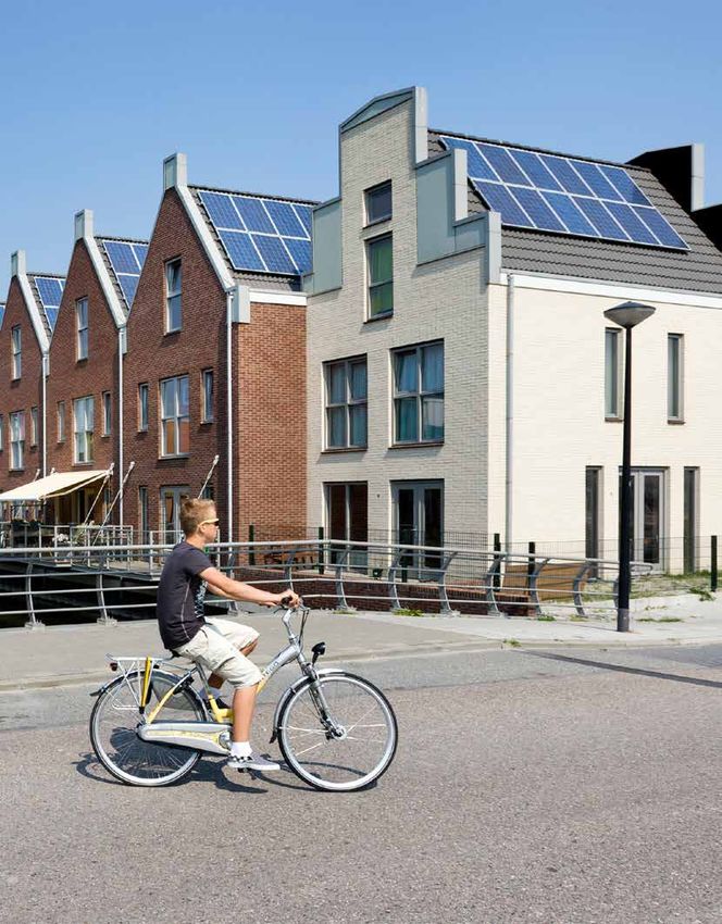
Self-consumption
& energy storage

        Energy. Anytime. Anywhere.
2
Energy. Anytime. Anywhere.

                        INDEX
Introduction4
Why choose Victron Energy for your Energy Storage system  6
Application example: Tiny House                           8
Application example: Smartflower                          9
Which system to choose                                   10
Monitoring12
Tools14
Accessories15
Technical information                                    19
About Victron Energy                                     62

                                                                            3
Introduction

Self-consumption or grid independence
The primary goal of a self-consumption system is to optimise       In an optimised self-consumption system, surplus energy is
the use of solar and/or wind power. The major obstacle in such     stored locally for local on demand use. Such energy storage
a system is that power generation times do not match with          is becoming an increasingly attractive proposition, especially
the actual times of power use. This results in a system being      with feed-in tariffs decreasing and grid supplies becoming
forced to import energy from the grid and export it when           less stable and more expensive.
there is a surplus.

Self-consumption versus off-grid systems
There are some major considerations which should be taken          Examples of this are heating pumps, chargers and the standby
into account when comparing an off-grid system with a self-        power of household equipment. In order to optimise PV usage
consumption system.                                                and limit the import of energy this base-load is the most
                                                                   efficient part to target.
An off-grid system is a system that is not (or mostly not)
connected to grid power and is used to supply the total
energy needs of the complete energy system. Therefore it is
sized to cope in a worst case scenario. This worst case scenario
can occur when there is simultaneous usage of high loads
which then requires a high power inverter for occasional use.

The other worst case scenario is the lack of ability to generate
energy in periods of overcast weather and/or wind outages.         Avoiding the import of the total energy need is possible but
This results in substantial battery storage to overcome this,      this would require a higher investment in the inverter, as it
which, like the large inverter power situation mentioned           must then be able to cover for high loads. Most high loads are
above, is only used on occasion.                                   however peak loads and active over a limited period of time.
                                                                   So even though this requires a high energy supply, the time
In general it can therefore be stated that an off-grid system is   period is limited and the energy value within this peak-load
oversized in both inverter power and storage capacity in order     period is quite low - so the investment in a larger inverter is
to deal with such situations.                                      often not justified.

For a self-consumption system this is different, as there is       When considering battery capacity, a self-consumption
always a grid present. With Grid assist functionality the grid     system is able to work with a smaller battery capacity. The
can be used seamlessly, whenever there is a high peak load,        energy stored in such a system is limited to the surplus PV
meaning the inverter can be sized according to the base load.      power as part of the generated PV power is directly used by
                                                                   the loads. In this case PV power is sized according to the base
The baseload is the part of the total energy-need which            load and any surplus energy is used overnight.
generally comes from low powered equipment and these
loads continue to draw energy almost constantly over the 24        More information:
hours of a day.                                                    https://www.victronenergy.com/upload/documents/
                                                                   Whitepaper-Self-Consumption-and-Grid-independence-
                                                                   with-the-Victron-Energy-Storage-Hub-EN.pdf

4
Energy. Anytime. Anywhere.

                        5
Why choose Victron Energy for your Energy Storage system

                                                     A wide range of inverter/charger sizes and configurations
                                                     Our inverter/charger models range from a small 500VA unit all
                                                     the way up to a 15kVA unit. Multiple units can be connected in
                                                     parallel and/or 3-phase configuration. Thus it is possible to create
                                                     systems ranging in power size from a small single phase system
                                                     up to an impressive 180kVA 3-phase system.

                                                     Unrivalled experience with battery storage systems
                                                     Victron Energy was founded in 1973, back then we started with
                                                     providing inverters and chargers for the marine industry. This
                                                     quickly expanded to the land based and automotive market. We
                                                     therefore have an unrivalled length of experience with battery
                                                     storage systems.

Reinout Vader showing first inverter

                                                     DC-Coupled PV or AC-Coupled PV. Or even a combination of
                                                     both
                                                     We can work with DC-Coupled PV: MPPT solar chargers. We have
                                                     a broad range of efficient MPPT solar chargers. Starting from the
                                                     MPPT 75V/15A (290 W charger) up to the 250V/100A (5.7kW solar
                                                     charger).
                                                     We can also work with AC-Coupled PV etc. We are compatible
                                                     with many brands of PV Inverters; with a strong collaboration
                                                     with Fronius PV Inverters.
                                                     We can even combine AC and DC coupled PV in one system.

                                                     Excellent remote monitoring and diagnostics tools
                                                     Our remote monitoring website (VRM) can display all your systems
                                                     data in a comprehensive graphical format. System settings can be
                                                     changed via the portal. Alarms can be received by e-mail.

6
Energy. Anytime. Anywhere.

               UPS no-break output, operate without any disruption
               Our inverter/charger takes over supplying power to the
               connected loads in the event of a grid or generator failure. This
               happens so fast (less than 20 milliseconds) that computers and
               other electronic equipment will continue to operate without any
               disruption.

               Wide range of compatible battery technologies
               We sell our own brand of lead acid and lithium batteries. Also,
               our programmable inverter/chargers work with a wide range of
               battery technologies, see the logos below.

Battery technologies we work with:

        And many more!

                                                                              7
Application example: Tiny House

Tiny House
This is an application example of a Tiny House. Tiny Houses are very small homes that enable simple living in a smaller, more
efficient space. They are usually made of wood, being creatively designed to maximise the utility of a small living space. The
principal reasons for living in a Tiny House are to live sustainably in a financially and environmentally conscious way, whilst at
the same time enjoying the resulting freedom.
The Tiny House in the photograph belongs to Marjolein Jonker. She lives in The Netherlands and has built her own Tiny House,
together with a team of specialists.

Victron equipment
The Tiny house of Marjolein is equipped with:
•    EasySolar
•    2 x 90A Lithium-ion batteries
•    BMV-700 Battery Monitor
•    Color Control GX
For additional information about Marjolein Jonker's Tiny House please visit: https://www.marjoleininhetklein.com/

                           PV panels               Easy Solar                                                      Color Control GX            Loads
                                              Charger/Inverter/MPPT

                                                                                                VE BUS

                                                                                                VE Direct

                                                                                                                               color control

                                                                                BMV-602
                                                                              battery monitor

                                                                                                            VE Direct
                                                                      SETUP                SELECT

                                                                                   +
                                                                                   -

      Public grid                                                Battery monitor

                                                        Battery
                                                   2 x 90Ah Lithium

8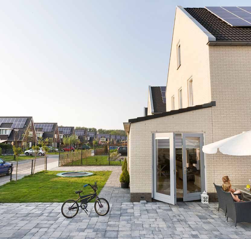
Energy. Anytime. Anywhere.

                                                                                                                                             Application example: Smartflower

                                                                                            Smartflower POP+
                                                                                            This is an application example of the Smartflower. The
                                                                                            Smartflower POP+ can not only turn the sun's energy into
                                                                                            electricity very efficiently; it can store it in sufficient quantities
                                                                                            too.

                                                                                            Enjoy the energy of the sun. Around the clock, almost
                                                                                            independently of the grid
                                                                                            Completely integrated in an innovative all-in-one solar system
                                                                                            that works on a plug-and-play principle like any normal
                                                                                            household appliance. The intelligent tracking function of the
                                                                                            PV modules ensures that the system makes the most efficient
                                                                                            use of the sun's energy at all times of the day and year, while
                                                                                            the battery is continuously recharged. So you can even enjoy
                                                                                            cloudy days with a bright smile on your face.

                                                                                            Monitoring – access to the most important system data
                                                                                            With your personal access to the Monitoring System you
                                                                                            can keep an eye on your current production, storage and
                                                                                            consumption figures at all times. The system also allows you
                                                                                            to make a number of different custom settings.

                                                                                            Victron inside & out
                                                                                            The Smartflower Pop+ uses a Victron Energy inverter, solar
                                                                                            charge controller and Lithium batteries, plus this standalone
                                                                                            unit connects to Victron Energy’s VRM web portal for system
                                                                                            monitoring.

                                                      Venus GX

                                      VE BUS

                                                      Venus GX

                                                                                     VE Direct                               2,3kWp
                 Charger/Inverter

                                                                                                                    MPPT charge controller

                                                                                            Blue Solar charge controller
                                                                                             MPPT 150 I 100 -MC4

                                                                                                 Battery

                                                                                                              pv

                                                                                                                                               230Vac
                           VE BUS
                                                                     BMV-602
                                                                   battery monitor

Public grid
                                                           SETUP                 SELECT

                                                                        +
                                                                        -

              VE Bus BMS                              Battery monitor

                        Battery 48Vdc / 4 x 90Ah Lithium                                                                                                   Loads

                                                                                                                                                                           9
Which system to choose

There is a solution for every situation, from simple to more complex solutions. We have different options available: PV in parallel,
AC-Coupled PV, DC-Coupled PV or a combination of all these options.

                                                                Option 1: PV in parallel
                                                                Most practical solution to add battery storage to an existing grid
                                                                connected PV system.

                                                                Option 2: AC-Coupled PV

10
Energy. Anytime. Anywhere.
Option 3: DC-Coupled PV
The size of the PV array and the PV inverter is not limited by the
maximum nominal power of the inverter/charger.
All options combined
Wired AC
sensor
11Monitoring The major considerations for installing a self-consumption system are often financially and/or morally driven. For both, the goal is to minimise the import of grid energy and to optimise the consumption of self-generated power. Modern inverter and battery monitoring technology helps to achieve this, by detecting how much energy to store and how and when to best use it. Besides this there is another important factor to consider. This factor is the energy behaviour of the end-user themselves. This can differ between households and it is heavily dependent on circumstances, which can change from day to day. This makes coding the software, to precisely achieve optimal use of energy, quite a challenge. If for example the washing machine is required on a particular day, the ideal day would be a sunny one just after the battery is (almost) full. Having said that direct power usage is preferable, which saves having to export energy to the grid or use battery power momentarily. In order to be able to make these kinds of energy use decisions, monitoring is crucial to fine tune and optimise energy use based on ever changing circumstances. This makes monitoring systems an essential feature for every self-consumption system. Tests have shown that users of self-consumption systems with monitoring score a much higher level of self-consumption than those systems which lack it. VRM: Live feed overview 12
Energy. Anytime. Anywhere.

                            Victron Energy self-consumption systems can offer the best of both worlds
                            By using a Color Control GX, with its easy to use display, a clear system overview will show all
                            the details needed to make crucial decisions as to which loads to use or to delay. Behind the
                            overview screens other advanced information can be found - enough to satisfy even the most
                            data-hungry users.

                            Venus GX
                            The Venus GX provides the same functionality as the Color Control GX, with a few extras:
                            - lower cost, mainly because it has no display or buttons
                            - 3 tank sender inputs
                            - 2 temperature inputs
Color Control GX
                            VRM Online Portal
                            All this data is automatically sent to our free remote monitoring website: the VRM Online Portal,
                            which allows even more options. It provides data analysis via the free VRM app which can be
                            used on virtually every smartphone, so even when away from the Color Control GX the system
                            can be easily monitored. Also the webserver is able to provide an advanced system overview,
                            such as calculations of total solar yield, power generation and graphs - for all the equipment
                            connected to the system.

Venus GX                    To get an impression of the VRM Online Portal, please visit:
                            https://vrm.victronenergy.com

                                                                                                                     VRM app

VRM: Solar Yield overview

                                                                                                                         13
Tools
There are a lot of tools available that make it easy to work with Victron Energy products, for both Victron installers as Victron
distributors. Whether you would like to configure and read out your Victron products with VictronConnect using your
smartphone, tablet or computer or you want to show or share your VRM site.
Instruction videos on Victron youtube channel
On our youtube channel you can watch Victron Energy instruction
videos.
https://www.youtube.com/user/VictronEnergyBV
ESS Webinar
There is a webinar about ESS available on our youtube channel,
in the languages English, Spanish, German and French.
MPPT Calculator Excel sheet
With the MPPT Calculator Excel sheet you can match solar
modules to MPPT charge controllers.
Download the Excel sheet from our software page:
https://www.victronenergy.com/support-and-downloads/
software
Victron Professional
With Victron Professional you can get insight into training
sessions, videos, firmware files, APIs and the latest news. If you
already use E-Order you can login with those credentials.
Sign up for Victron Professional here:
https://professional.victronenergy.com
VRM World: View shared VRM sites around the world
Ever wanted to show your clients, friends, colleagues how much
solar energy your installation is generating or indeed any other
data that you can see on your VRM site? Well now you can – using
VRM World.
You need a VRM account to be able to view shared VRM sites. In
your VRM portal it is possible to publicly share on VRM World.
Visit VRM World here:
https://vrm.victronenergy.com/world/
14Energy. Anytime. Anywhere.
Accessories
Our systems are comprised of various components. Some of which are specifically designed for specific markets. Other
Victron components are applicable for a wide range of applications. You are able to find the specifications and other detailed
information about these components in the ‘Technical Information’ section.
Battery Monitor
Key tasks of the Victron Battery Monitor are measuring charge
and discharge currents as well as calculating the state-of-charge
and time-to-go of a battery. An alarm is sent when certain limits
are exceeded (such as an excessive discharge). It is also possible
for the battery monitor to exchange data with the Victron Global
Remote. This includes sending alarms.
Color Control GX
The Color Control GX provides intuitive control and monitoring
for all products connected to it. The list of Victron products that
can be connected is endless: Inverters, Multis, Quattros, MPPT
150/70, BMV-700 series, Skylla-i, Lynx-Ion and even more.
Venus GX
The Venus GX provides the same functionality as the Color Control
GX, with a few extras:
- lower cost, mainly because it has no display or buttons
- 3 tank sender inputs
- 2 temperature inputs
MPPT Control
The MPPT Control lets you see the status as well as setup all
BlueSolar and SmartSolar MPPT Charge Controllers that have
a VE.Direct communications port. The new MPPT Control is
mounted in the familiar BMV-700 series housing, maintaining
a consistent and professional look to your panels and systems
monitoring equipment.
15Accessories
Anti-islanding made easy: the anti-islanding box
The anti-islanding box is a complete pre-wired and easy to
install anti-islanding device consisting of a Ziehl anti-islanding
relay (model UFR1001E or model SPI1021), the required circuit
breakers and a 63A contactor. For specifications of the Ziehl relay,
see http://www.ziehl.de.
Energy Meter
The ET112 (for single phase max. 100A) and the ET340 (for three
phase max. 65A) Energy Meters are typically used in an Energy
Storage System. To measure the power and energy of the whole
application at the distribution box. Or to measure the output of
a PV Inverter, to display the data on the Color Control GX and the
VRM Portal.
AC Current sensor - single phase - max 40A
The AC Current sensor is a simple external current sensor used
to measure AC Current, Power (VA) and calculate energy of a
PV Inverter connected to the AC input or output of a Multi or
Quattro. These values can then be displayed and sent to the VRM-
website by the Color Control. The two measurement wires can be
connected to the AUX and/or temperature sense input of a Multi
or Quattro.
Zigbee to USB converter & Zigbee to RS485
Zigbee to USB converter, DRF2618A, DTK
Zigbee to RS485 converter, DRF2619A, TDK
16Energy. Anytime. Anywhere.
Ziehl Voltage and frequency relay UFR1001E
The UFR1001E monitors voltage and frequency in plants for own
generation of electricity. It fulfills the requirements of VDE-AR-N
4105 bdew-directive, G59/3, G83/2 and ÖVE/ÖNORM E 8001-4-
712:2009 for generators connected to the public grid.
For more information, we refer you to the datasheet and
certificates below which are available to download. Or visit www.
ziehl.de and look for the UFR1001E under the Mains monitoring
group.
Ziehl Voltage and Frequency Relay SPI1021
Voltage- and Frequency-Relay with integrated Vector-Shift-Relay
Grid- and Plant Protection.
For more information, we refer you to the datasheet and
certificates below which are available to download. Or visit www.
ziehl.de and look for the SPI1021 under the Mains monitoring
group.
17Note - for our newest datasheets please refer to our website:
www.victronenergy.com
TECHNICAL INFORMATION
EasySolar 12V and 24V, 1600VA 20
EasySolar 3kVA & 5kVA with Color Control panel 22
MultiGrid 3000 VA 24
MultiPlus-II 3000VA & 5000VA 26
ECOmulti29
Phoenix inverters Smart 1600VA & 2000VA 32
Phoenix inverters 1200VA - 5000VA 230V 34
MultiPlus inverter/charger 800VA - 5kVA 230V 36
Quattro inverter/charger 3kVA - 15kVA 230V 38
MultiPlus inverter/charger 2kVA and 3kVA 120V 40
Quattro inverter/charger 3kVA - 10kVA 120V 42
Color Control GX 44
Venus GX 48
BMV-712 Smart: Bluetooth inside 50
BlueSolar and SmartSolar MPPT Charge Controllers - Overview 52
SmartSolar charge controller MPPT 75/10, 75/15, 100/15 & 100/20 53
SmartSolar charge controller MPPT 100/30 & 100/50 54
SmartSolar charge controller MPPT 150/35 55
SmartSolar charge controller MPPT 150/45 & MPPT 150/100 56
SmartSolar charge controller MPPT 250/60, 250/70, 250/85 & 250/100 57
24V 180Ah Lithium-ion battery and Lynx-ion 58
Lithium-Ion HE Battery and Lynx Ion BMS 60
1818Energy. Anytime. Anywhere.
1919EasySolar 12V and 24V, 1600VA
www.victronenergy.com
EasySolar
The 12V and
all-in-one 24V,
solar 1600VA
power solution
z
All-in-one solar power solution
The EasySolar combines a MPPT solar charge controller, an inverter/charger and AC distribution
in one enclosure.
The product is easy to install, with a minimum of wiring.
The solar charge controller: Blue Solar MPPT 100/50
Up to three strings of PV panels can be connected to three sets of MC4 (PV-ST01) PV connectors.
The inverter/charger: MultiPlus Compact 12/1600/70 or 24/1600/40
The MPPT charge controller and the MultiPlus Compact inverter/charger share the DC battery
cables (included). The batteries can be charged with solar power (BlueSolar MPPT) and/or with AC
power (inverter/charger) from the utility grid or a genset.
AC distribution
The AC distribution consists of a RCD (30 mA/16 A) and four AC outputs protected by two 10A
and two 16A circuit breakers.
One 16A output is controlled by the AC input: it will switch on only when AC is available.
PowerAssist
Unique PowerAssist technology protects the utility or generator supply from being overloaded
by adding extra inverter power when needed.
Unique solar application software
Several software programs (Assistants) are available to configure the system for various grid
interactive or stand-alone applications. Please see
http://www.victronenergy.nl/support-and-downloads/software/
VE.Direct
MPPT 100|50
Victron Energy B.V. | De Paal 35 | 1351 JG Almere | The Netherlands
General phone: +31 (0)36 535 97 00 | Fax: +31 (0)36 535 97 40
E-mail: sales@victronenergy.com | www.victronenergy.com
20Energy. Anytime. Anywhere.
EasySolar EasySolar 12/1600/70 EasySolar 24/1600/40
Inverter/charger
Transfer switch 16A
INVERTER
Input voltage range 9,5 – 17V 19 – 33V
‘Heavy duty’ output AC 0 16A
Output voltage: 230 VAC ± 2%
Output AC1, 2, 3
Frequency: 50 Hz ± 0,1% (1)
Cont. output power at 25°C (3) 1600VA / 1300W
Cont. output power at 40°C 1200W
Peak power 3000W
Maximum efficiency 92% 94%
Zero load power 8W 10W
Zero load power in search mode 2W 3W
CHARGER
Input voltage range: 187-265VAC
AC Input
Input frequency: 45 – 65Hz Power factor: 1
Charge voltage 'absorption' 14,4V 28,8V
Charge voltage 'float' 13,8V 27,6V
Storage mode 13,2V 26,4V
Charge current house battery (4) 70A 40A
Charge current starter battery (A) 4
Battery temperature sensor Yes
Programmable relay (5) Yes
Protection (2) a–g
Solar Charge Controller
Model MPPT 100/50
Maximum output current 50A
Maximum PV power, 6a,b) 700W 1400W
Maximum PV open circuit voltage 100V 100V
Maximum efficiency 98%
Self-consumption 10 mA
Charge voltage 'absorption', default setting 14,4V 28,8V
Charge voltage 'float', default setting 13,8V 27,6V
Charge algorithm multi-stage adaptive
Temperature compensation -16mV/°C -32mV/°C
Protection a-g
COMMON CHARACTERISTICS
Operating temp. range -20 to +50°C (fan assisted cooling)
Humidity (non-condensing): max 95%
ENCLOSURE
Material & Colour aluminium (blue RAL 5012)
Protection category IP 21
Battery-connection Battery cables of 1.5 meter
PV connection Three sets of MC4 (PV-ST01) PV connectors.
230 V AC-connection G-ST18i connector
Weight 15kg
Dimensions (hxwxd) 745 x 214 x 110mm
STANDARDS
Safety EN 60335-1, EN 60335-2-29, EN 62109
Emission / Immunity EN 55014-1, EN 55014-2, EN 61000-3-3
Automotive Directive 2004/104/EC
1) Can be adjusted to 60Hz and to 240V 3) Non-linear load, crest factor 3:1
2) Protection 4) At 25°C ambient
a. Output short circuit 5) Programmable relay which can be set for general alarm, DC under
b. Overload voltage or genset start signal function
c. Battery voltage too high 6a) If more PV power is connected, the controller will limit input power to
d. Battery voltage too low 700W resp. 1400W
e. Temperature too high
6b) PV voltage must exceed Vbat + 5V for the controller to start.
f. 230 VAC on inverter output
g. Input voltage ripple too high
Thereafter minimum PV voltage is Vbat + 1V
21EasySolar 3 kVA & 5 kVA with Color Control panel
EasySolar 3kVA & 5kVA with Color Control panel www.victronenergy.com
The all-in-one solar power solution
The all-in-one solar power solution
The EasySolar combines a MPPT solar charge controller, an inverter/charger and AC distribution
in one enclosure.
The product is easy to install, with a minimum of wiring.
Color Control panel
Two outstanding functions:
- Prioritizes battery charging by the MPPT charge controller
- Connects to the internet, enabling remote monitoring (VRM website) and remote control.
AC distribution
The AC distribution consists of a RCD (30mA / 63A) and four AC outputs protected by two 10A
and two 16A circuit breakers.
An additional 16A output is controlled by the AC input: it will switch on only when AC is available.
PowerAssist
Unique PowerAssist technology protects the utility or generator supply from being overloaded
by adding extra inverter power when needed.
Unique solar application software
Several software programs (Assistants) are available to configure the system for various grid
interactive or stand-alone applications. Please see
http://www.victronenergy.nl/support-and-downloads/software/
EasySolar 3 kVA
EasySolar 5 kVA
Victron Energy B.V. | De Paal 35 | 1351 JG Almere | The Netherlands
General phone: +31 (0)36 535 97 00 | Fax: +31 (0)36 535 97 40
E-mail: sales@victronenergy.com | www.victronenergy.com
22Energy. Anytime. Anywhere.
EasySolar 24/3000/70-50 EasySolar 48/3000/35-50 EasySolar 48/5000/70-100
EasySolar
MPPT150/70 MPPT150/70 MPPT150/100
INVERTER/CHARGER
Transfer switch 50A 50A 100A
INVERTER
Input voltage range 19 – 33V 38 – 66V 38 – 66V
‘Heavy duty’ output AC 2 16 A
Output voltage: 230VAC ± 2%
Output AC 1a, 1b, 1c, 1d
Frequency: 50 Hz ± 0,1% (1)
Cont. output power at 25°C (3) 3000VA / 2400W 3000VA / 2400W 5000VA / 4000W
Cont. output power at 40°C 2200W 2200W 3700W
Cont. output power at 65°C 1700W 1700W 3000W
Peak power 6000W 6000W 10000W
Maximum efficiency 94% 95% 95%
Zero load power 20W 25W 35W
Zero load power in search mode 10W 12W 15W
CHARGER
Input voltage range: 187-265 VAC
AC Input
Input frequency: 45 – 65 Hz Power factor: 1
Charge voltage 'absorption' 28,8V 57,6V 57,6V
Charge voltage 'float' 27,6V 55,2V 55,2V
Storage mode 26,4V 52,8V 52,8V
Charge current 70A 35A 70A
Battery temperature sensor yes
Programmable relay (5) yes
Protection (2) a-g
SOLAR CHARGE CONTROLLER
Model MPPT 150/70-MC4 MPPT 150/70-MC4 MPPT 150/100-MC4
Maximum output current (4) 70A 70A 100A
Maximum PV power 2000W 4000W 5800W
Maximum PV open circuit voltage 150V
Maximum efficiency 98%
Self-consumption 10mA
Charge voltage 'absorption', default setting 28,8V 57,6V 57,6V
Charge voltage 'float', default setting 27,6V 55,2V 55,2V
Charge algorithm multi-stage adaptive
Temperature compensation -16 mV / °C -32 mV / °C -64 mV / °C
Protection a–g
COMMON CHARACTERISTICS
Operating temp. range -40 to +65°C (fan assisted cooling)
Humidity (non-condensing): max 95%
ENCLOSURE
Material & Colour aluminium (blue RAL 5012)
Protection category IP 21
Battery-connection Four M8 bolts (2 plus and 2 minus connections)
Three sets of MC4
PV connection Two sets of MC4 PV connectors.
PV connectors
230 V AC-connection Screw terminals 13 mm2 (6 AWG)
Weight 28kg 28kg 48kg
Dimensions (hxwxd) 810 x 258 x 218 810 x 258 x 218 877 x 328 x 241
STANDARDS
Safety EN 60335-1, EN 60335-2-29, EN 62109-1
Emission / Immunity EN 55014-1, EN 55014-2, EN 61000-3-3, EN 61000-6-3, EN 61000-6-2, EN 61000-6-1
Anti-islanding See our website
1) Can be adjusted to 60Hz and to 240V 3) Non-linear load, crest factor 3:1
2) Protection: 4) At 25°C ambient
a. Output short circuit 5) Programmable relay which can be set for general alarm, DC under
b. Overload voltage or genset start signal function
c. Battery voltage too high
d. Battery voltage too low
e. Temperature too high
f. 230 VAC on inverter output
g. Input voltage ripple too high
23MultiGrid 3000VA
www.victronenergy.com
The MultiGrid
flexible energy
3000VAstorage and self-consumption solution
Combined with the flexibility of a MultiPlus bidirectional converter
The MultiPlus range of bidirectional converters is the worldwide product of choice on boats and vehicles to generate AC
power, and to recharge batteries, either with shore power or an onboard AC generator.
The MultiPlus also is the industry standard in on-grid and off-grid energy storage systems and is approved for use in
energy storage and self-consumption systems in the UK (G83/2 and G59-3-1 standards).
Several hardware and firmware modifications were needed to qualify for VDE-AR-N 4105 and several other country
specific energy storage related standards.
The resulting product is the MultiGrid.
The MultiGrid fits seamlessly in all common energy storage topologies
There is no one-size-fits-all solution to energy storage. The building blocks, topology and control systems will depend on local conditions and
regulations.
The MultiGrid hardware, together with a wide range of software tools, seamlessly fits in all common topologies, shown in the pictures below.
More detail can be found in our Energy Storage brochure.
Grid in-line topology with MPPT solar charge controller Grid in-line topology with PV inverter
A solar charge controller supplies PV power to the battery. PV power is converted to AC.
The stored energy is used by the MultiGrid to supply AC power to the load and, if The MultiGrid will use excess PV power to charge the batteries or to feed power back into
required, to feed excess solar power back into the grid. the grid, and will discharge the battery or use power from the grid to supplement a
In case of a utility power outage, the MultiGrid will disconnect the grid and shortage of PV power.
continue to supply the load. In case of a power outage, the MultiGrid will disconnect the grid and continue to supply the
load.
Grid parallel topology with MPPT solar charge controller Grid parallel topology with PV inverter
Certain critical loads only are protected against a power outage. Certain critical loads only are protected against a power outage.
The MultiGrid will use data from the power meter to optimise self-consumption and, if The MultiGrid will use data from the power meter to optimise self-consumption and, if
required, to prevent back feed of excess solar power into the grid. required, to prevent back feed of excess solar power into the grid.
Victron Energy B.V. | De Paal 35 | 1351 JG Almere | The Netherlands
General phone: +31 (0)36 535 97 00 | Fax: +31 (0)36 535 97 40
E-mail: sales@victronenergy.com | www.victronenergy.com
24Energy. Anytime. Anywhere.
24 Volt 24/3000/70
MultiGrid
48 Volt 48/3000/35
PowerControl & PowerAssist Yes
Transfer switch 50 A
INVERTER
Input voltage range 19 – 33 V 38 – 66 V
Output voltage: 230 VAC ± 2%
Output
Frequency: 50 Hz ± 0,1% (1)
Cont. output power at 25°C (3) 3000 VA
Cont. output power at 25°C 2400 W
Cont. output power at 40°C 2200 W
Cont. output power at 65°C 1700 W
Peak power (W) 6000 W
Maximum efficiency 94 / 95 %
Zero load power 20 / 25 W
Zero load power in AES mode 15 / 20 W
Zero load power in Search mode 10 / 12 W
CHARGER
Grid parallel topology with PV inverter
Input voltage range: 187-265 VAC
Similar to Hub 4-2 but in this topology the PV inverter will shut down in case of AC Input
a power outage. Input frequency: 45 – 65 Hz
Certain critical loads only are protected against a power outage. Charge voltage 'absorption' 28,8 / 57,6 V
The MultiGrid will use data from the power meter to optimise self- Charge voltage 'float' 27,6 / 55,2 V
consumption and, if required, to prevent back feed of excess solar power into
Storage mode 26,4 / 52,8 V
the grid.
Maximum battery charge current (4) 70 / 35 A
Battery temperature sensor yes
GENERAL
Auxiliary output Yes (16 A) Switches off when no external AC source available
Programmable relay (5) Yes
Protection (2) a-g
For parallel and three phase operation,
VE.Bus communication port
remote monitoring and system integration
General purpose com. port Yes
Remote on-off Yes
Operating temperature range -40 to +65°C (fan assisted cooling)
Humidity (non-condensing) max 95%
ENCLOSURE
Material & Colour Aluminium, blue RAL 5012
Protection category IP 21
Four M8 bolts
Battery-connection
(2 plus and 2 minus connections)
230 V AC-connection Screw terminals 13 mm² (6 AWG)
Weight 18 kg
Color Control Panel (CCGX) Dimensions (hxwxd) 362 x 258 x 218 mm
Provides intuitive system control and monitoring STANDARDS
Besides system monitoring and control the CCGX enables access to our free
remote monitoring website: the VRM Online Portal EN-IEC 60335-1, EN-IEC 60335-2-29,
Safety
EN-IEC 62109-1, EN-IEC 62109-2
EN 55014-1, EN 55014-2
Emission, Immunity EN-IEC 61000-3-2, EN-IEC 61000-3-3
IEC 61000-6-1, IEC 61000-6-2, IEC 61000-6-3
Uninterruptible power supply IEC 62040-1, AS 620401.1
VDE-AR-N 4105, AS/NZS 4777.2, NRS 097-2-1,
Anti-islanding
UTE C15-712-1, C10/11, RD 1699-RD 413, TOR D4
1) Can be adjusted to 60 HZ
2) Protection key:
a) output short circuit
b) overload
c) battery voltage too high
d) battery voltage too low
e) temperature too high
f) 230 VAC on inverter output
g) input voltage ripple too high3) Non-linear load, crest factor 3:1
3) Non-linear load, crest factor 3:1
4) At 25°C ambient
5) Programmable relay which can be set for general alarm, DC under voltage or genset start/stop function
AC rating: 230V / 4A, DC rating: 4A up to 35VDC and 1A up to 60VDC
VRM app
Monitor and manage your Victron Energy
system from your smart phone and tablet.
Available for both iOS and Android.
VRM Portal
Our free remote monitoring website (VRM) can
display all your systems data in a comprehensive
graphical format. System settings can be
changed remotely via the portal. Alarms can be
received by e-mail.
Victron Energy B.V. | De Paal 35 | 1351 JG Almere | The Netherlands 25
General phone: +31 (0)36 535 97 00 | Fax: +31 (0)36 535 97 40MultiPlus-II Inverter/Charger
\ 3000VA & 5000VA
MultiPlus-II
MultiPlus-II 48/3000/35-32 & 48/5000/70-50
A MultiPlus, plus ESS (Energy Storage System) functionality
The MultiPlus-II combines the functions of the MultiPlus and the MultiGrid.
It has all the features of the MultiPlus, plus an external current sensor option which extends the PowerControl and
PowerAssist function to 50A resp 100A
It also has all the features of the MultiGrid with built-in anti-islanding and an increasingly long list of country approvals.
PowerControl and PowerAssist - Boosting the capacity of grid or generator power
A maximum generator or grid current can be set. The Multi will then take account of other AC loads and use whatever is extra
for battery charging, thus preventing the generator or grid from being overloaded (PowerControl function).
PowerAssist takes the principle of PowerControl to a further dimension. Where peak power is so often required only for a
limited period, the Multi will compensate insufficient generator, shore or grid power with power from the battery. When the
load reduces, the spare power is used to recharge the battery.
ESS: Energy Storage Systems
The MultiPlus can be used in off grid as well as grid connected PV and other alternative energy systems.
Several system configurations are possible, for more detailed information see the ESS Design and configuration manual.
On-site monitoring and control
Several options are available: Battery Monitor, Digital Multi Control Panel, Color Control Panel, Bluetooth (Venus GX or Color Control panel needed),
laptop or computer.
Remote configuring and monitoring
Install a Venus GX or a Color Control Panel to connect to the internet.
Data can be stored and displayed on our VRM (Victron Remote Management) website, free of charge.
When connected to the Ethernet, systems can be accessed remotely and settings can be changed.
Standard mobile or off-grid application Standard mobile or off-grid application with external current sensor
Loads that should shut down when AC input power is not available can be Maximum current sensing range: 50A resp 100A
connected to a second output (not shown). These loads will be taken into account
by the PowerControl and PowerAssist function in order to limit AC input current to
a safe value.
Grid parallel topology with MPPT solar charge controller Grid in-line topology with PV inverter
Certain critical loads only are protected against a power outage. PV power is directly converted to AC.
The MultiPlus-II will use data from an external AC current sensor or power meter to The MultiPlus-II will use excess PV power to charge the batteries or to feed power
optimise self-consumption and, if required, to prevent back feed of excess solar back into the grid, and will discharge the battery or use power from the grid to
power into the grid. In case of a power outage, the MultiPlus-II will continue to supplement a shortage of PV power. In case of a power outage, the MultiPlus-II
supply the critical loads will disconnect the grid and continue to supply the loads.
26Energy. Anytime. Anywhere.
MultiPlus-II 48/3000/35-32 48/5000/70-50
PowerControl & PowerAssist Yes
Transfer switch 32 A 50 A
Maximum AC input current 32 A 50 A
INVERTER
DC Input voltage range 38 – 66 V
Output voltage: 230 VAC ± 2%
Output
Frequency: 50 Hz ± 0,1% (1)
Cont. output power at 25°C (3) 3000 VA 5000VA
Cont. output power at 25°C 2400 W 4000W
Cont. output power at 40°C 2200 W 3700W
Cont. output power at 65°C 1700 W 3000W
Maximum apparent feed-in power 2500VA 4000VA
Peak power 5500 W 9000W
Maximum efficiency 95 % 96%
Zero load power 11 W 18W
Zero load power in AES mode 7W 12W
Grid parallel topology with PV inverter Zero load power in Search mode 2W 2W
In this topology the PV inverter will shut down in case of a CHARGER
power outage. Input voltage range: 187-265 VAC
AC Input
The MultiPlus-II will use data from the external AC current Input frequency: 45 – 65 Hz
sensor or power meter to optimise self-consumption and, if Charge voltage 'absorption' 57,6 V
required, to prevent back feed of excess solar power into the Charge voltage 'float' 55,2 V
grid. Storage mode 52,8 V
Maximum battery charge current (4) 35 A 70A
Battery temperature and voltage sensor VE.Bus Smart dongle (optional)
GENERAL
Auxiliary output Yes (32 A)
External AC current sensor (optional) 50 A 100 A
Programmable relay (5) Yes
Protection (2) a-g
For parallel and three phase operation,
VE.Bus communication port remote monitoring and system integration
General purpose com. port Yes, 2x
Remote on-off Yes
Operating temperature range -40 to +65°C (fan assisted cooling)
Humidity (non-condensing) max 95%
ENCLOSURE
Material & Colour steel, blue RAL 5012
Color Control Panel (CCGX) Protection category IP22
Provides intuitive system control and monitoring Battery-connection Two M6 bolts
Besides system monitoring and control the CCGX enables access to 230 V AC-connection Screw terminals 13 mm² (6 AWG)
our free remote monitoring website: the VRM Online Portal Weight 18 kg 29 kg
Dimensions (hxwxd) 499 x 268 x 141 mm 560 x 320 x 141 mm
STANDARDS
EN-IEC 60335-1, EN-IEC 60335-2-29,
Safety
EN-IEC 62109-1, EN-IEC 62109-2
EN 55014-1, EN 55014-2
Emission, Immunity EN-IEC 61000-3-2, EN-IEC 61000-3-3
IEC 61000-6-1, IEC 61000-6-2, IEC 61000-6-3
Uninterruptible power supply IEC 62040-1, AS 620401.1
VDE-AR-N 4105, TOR-D4, AS/NZS 4777.2,
Anti-islanding NRS 097-2-1, UTE C15-712-1, C10/11,
RD 1699-RD 413, G59/3-2, G83/2
1) Can be adjusted to 60 Hz
2) Protection key:
a) output short circuit
b) overload
c) battery voltage too high
d) battery voltage too low
e) temperature too high
f) 230 VAC on inverter output
VRM app
g) input voltage ripple too high
Monitor and manage your Victron Energy 3) Non-linear load, crest factor 3:1
system from your smart phone and tablet. 4) At 25°C ambient
Available for both iOS and Android. 5) Programmable relay which can be set for general alarm, DC under voltage or genset start/stop
function. AC rating: 230V / 4A, DC rating: 4A up to 35VDC and 1A up to 60VDC
Current sensor 100A:50mA Digital Multi Control Panel
To implement PowerControl and A convenient and low-cost solution for remote
VRM Portal PowerAssist and to optimize self- monitoring, with a rotary knob to set
Our free remote monitoring website (VRM) will display all your system data in consumption with external current PowerControl and PowerAssist levels.
a comprehensive graphical format. System settings can be changed remotely sensing.
via the portal. Alarms can be received by e-mail. Maximum current: 50A resp. 100A
Length of connection cable: 1 m.
(must be ordered separately)
Victron Energy B.V. | De Paal 35 | 1351 JG Almere | The Netherlands
General phone: +31 (0)36 535 97 00 | E-mail: sales@victronenergy.com
www.victronenergy.com 27ECOmulti
BIDERECTIONAL CONVERTER
In case of overload the ECOmulti
GridAssist function
will import power from the grid to prevent system shutdown.
Maximum AC current feed-through 50 A
AC voltage 230 V 50 Hz single phase
Cont. output power at 25 °C 3000 VA
Cont. output power at 25 °C 2500 W
Cont. output power at 40 °C 2200 W
Peak power 6000 W
Maximum efficiency 94%
Power factor range (when connected to the grid) 0,7 inductive to 0,7 capacitive (programmable)
Zero-load power (W) 15 W
10 W
Zero load power in AES mode (island mode operation with AC output lowered
to 200 V when load < 50 Watt)
Charge voltage 'absorption' 28,2 V
Charge voltage 'float’ 26,7 V
Maximum charge current 70 A
Maximum battery depth of discharge (DoD) 80%
To connect additional loads once the battery
Auxiliary output
has been fully charged: 16 A relay
Programmable relay For monitoring, alarm or other purposes
For parallel and three phase operation, remote monitoring, remote control and system
VE.Bus communication port
integration
General purpose communication port Yes
Remote on-off Yes
BATTERY
Technology Lithium Iron Phosphate
Nominal voltage 25,6 V
Nominal energy at 25°C 2,3 kWh
Nominal capacity at 25°C 90 Ah
Nominal capacity at 0°C 72 Ah
Nominal capacity at -20°C 45 Ah
Cell balancing, and system shutdown in case of
Battery Management System
cell over voltage, cell under voltage and over temperature
Cycle life, 80% DoD 2000 cycles
Cycle life, 70% DoD 3000 cycles
Cycle life, 50% DoD 5000 cycles
Max storage time at 25 °C 1 year
OTHER
Graphical display
Graphical User Interface (GUI)
Display Ethernet (standard) and Wifi (optional) for remote monitoring and control
Data storage and graphical display on vrm.victronenergy.com
Android and iPhone apps
Operating temperature -20 to + 40°C
Storage temperature -40 to + 50°C
Protection category IP22
Humidity 95% non condensing
System: 5 years
Warranty
Battery: 3 years full warranty plus 7 years prorated warranty
ENCLOSURE
Colour Blue RAL 5012
Weight Without battery: 28 kg With battery: 60 kg
Dimensions (hxwxd) 475 x 575 x 360 mm
STANDARDS
Safety EN 60335-1, EN 60335-2-29, VDE-AR-N 4105
Emission, Immunity EN55014-1, EN 55014-2, EN 61000-3-3
Victron Energy B.V. / De Paal 35
1351 JG Almere / The Netherlands
Phone: +31 (0)36 535 97 00
Fax: +31 (0)36 535 97 40
e-mail: sales@victronenergy.com
www.victronenergy.com
28Energy. Anytime. Anywhere.
ECOmulti
simple wall mounted energy storage solution
Nighttime
During the night the ECOmulti is disconnected from the grid. The home is powered by energy stored in
the battery. The ECOmulti will reconnect the grid when the battery is discharged.
Battery charging
The next day, when the PV array produces sufficient power to supply the loads and to start charging the
battery, the ECOmulti will regulate charge current to absorb nearly 100% of the surplus PV power.
Discharging during the day
When PV output is reduced by clouds or when a power hungry load is switched on, resulting in no surplus
PV power available, battery charging will stop. Insufficient PV power will be supplemented by power from
the ECOmulti. In case of overload power will be imported from the grid to supplement power from the
ECOmulti (GridAssist function), and system shut down due to overload will be prevented.
Battery fully charged
Once the battery is fully charged, additional loads (for example the water heater) can be switched on, or
surplus power will be exported to the grid.
End of the day
The ECOmulti disconnects from the grid about 10 minutes after PV power has become insufficient to
provide any charge current. In order to prevent false disconnections due to lack of sun during the day, the
inverter/charger also uses an internal timer to predict the end of the day.
UPS function
When the grid fails, the ECOmulti will continue to power the home.
29ECOmulti
ECOmulti
A simple wall mounted energy storage solution
100%
Sizing the PV array State of charge
Sufficient energy must be
75%
harvested to recharge the
battery and to power the
home, even on a reasonably 50%
clear winter day.
25%
At roughly 50 degrees
latitude (Seattle, 0%
London, Amsterdam, Berlin, ECOmulti app
00:00
02:00
04:00
06:00
07:00
10:00
12:00
14:00
16:00
18:00
20:00
22:00
München) the two person
energy conscious household
will need a 2,5 kWp array.
A four person household Why 2,3 kWh?
would need a 5 kWp array. Whenever PV output exceeds consumption, storing excess output for later use
will increase self-consumption.
At roughly 30 to 40 degrees
latitude (Los Angeles, However
Marseille, Sevilla) a 1 kWp - PV harvest will fluctuate from season to season, from day to day and also within the day.
resp. 2 kWp array will do. - Electricity consumption is likewise fluctuating: working days, weekends and holiday
periods will all result in different consumption patterns.
A larger PV array will increase
feedback into the grid, but A 2,3 kWh Li-ion battery is an efficient solution for a two person energy conscious household.
not substantially increase Energy consumption from dusk to dawn will be 2 kWh or more, even when no energy hungry
battery utilization and self appliances like a dishwasher or clothes dryer are used. A fully charged 2,3 kWh battery will there-
sufficiency. fore be discharged before the sun starts shining again.
Increasing storage capacity The average household with two children would fully utilize a 4,6 kWh Li-ion battery; one addi-
More battery storage tional battery module.
capacity will reduce feedback
into the grid and increase self
sufficiency, especially during
the summer season. Winter Spring Summer Autumn
To increase self sufficiency 100%
during wintertime both the
battery and the PV array have
to be enlarged.
50%
10%
100%
10
kWh
Solar yield
9
8
50%
7
6
5
4
PV Production 10%
3
2 Self-consumption
1 Self sufficiency
0
mon tue wed thur fri sat sun
13-05 14-05 15-05 16-05 17-05 18-05 19-05 Typical seasonal variations at roughly 50 degrees latitude ~ Seattle, London, Amsterdam, Berlin,
To Grid München ~ with battery and without battery.
To Battery
Direct use
Two person energy conscious household Four person energy conscious household
Consumption: 2500 kWh per year Consumption: 4500 kWh per year
PV array: 2,5 kWp PV array: 5 kWp
Battery: 2,3 kWh Li-ion Battery: 4,6 kWh Li-ion
30Energy. Anytime.
Energy. Anywhere.
Anytime. Anywhere.
www.victronenergy.com
A simple wall mounted energy storage solution
The ECOmulti can be wall mounted, is easy to install, easy to program and easy to operate.
Extremely flexible
- Energy storage can be increased by adding battery modules.
- AC power can be increased by paralleling ECOmulti modules.
- Three ECOmulti modules can be configured for three phase operation.
- Two ECOmulti modules can be configured for split phase operation.
More self-consumption, more independence
With 2,3 kWh Li-ion storage capacity and a 3 kVA bidirectional inverter, the ECOmulti reduces dependence on power
from the grid.
The growing interest in self-consumption is driven by increasing retail electricity prices and simultaneously
decreasing feed in tariffs. Feed in tariffs are decreasing a. o. because it becomes increasingly difficult, and
expensive, to ensure stability of the grid as more solar and wind power comes on line. Simultaneously, the retail price
of electricity is increasing, to cover these same costs plus the cost to keep conventional power plants in hot standby
to back-up renewable power generation in case the sun is not shining and/or the wind is not blowing.
The ECOmulti meets the German interconnection standard VDE-AR-N 4105 and the Incentive Program for Solar Energy Storage
Systems Marktanreizprogramm für Batteriespeicher.
With Intelligent Battery and Load Management the ECOmulti can limit power export to the grid to at most 60% of the installed Wp
capacity; KfW-Programm Erneuerbare Energien “Speicher”.
According to the Fraunhofer-Institut für Solare Energiesysteme (ISE), a household that consumes 4500 kWh per year can reduce
energy import from the grid by 60% when installing a 5 kWp solar array combined with 4 kWh usable energy storage.
For more information please download our white paper
Self-consumption or grid independence from
www.victronenergy.com.
Inverter 1
1
EcoMulti
2
2
Generation
Consumption
Feed-in supply
31Phoenix Inverters Smart 1600VA & 2000VA
Phoenix inverters Smart 1600VA & 2000VA www.victronenergy.com
Bluetooth built-in: fully configurable with a tablet or smartphone
• Low battery voltage alarm
• Low battery voltage cut-off and restart levels
• Dynamic cut-off: load dependent cut-off level
• Output voltage: 210 - 245V
• Frequency: 50 Hz or 60 Hz
• ECO mode on/off and ECO mode sense level
• Alarm relay
Monitoring:
• In- and output voltage, load and alarms
VE.Direct communication port
The VE.Direct port can be connected to a computer (VE.Direct to USB interface cable needed) to
configure and monitor the same parameters.
Phoenix Inverter
Smart 12/2000 Proven reliability
The full bridge plus toroidal transformer topology has proven its reliability over many years.
The inverters are short circuit proof and protected against overheating, whether due to overload
or high ambient temperature.
High start-up power
Needed to start loads such as power converters for LED lamps, halogen lamps or electric tools.
ECO mode
When in ECO mode, the inverter will switch to standby when the load decreases below a preset
value. Once in standby the inverter will switch on for a short period every 2,5 seconds
(adjustable).
If the load exceeds the preset level, the inverter will remain on.
Remote on/off
A remote on/off switch or relay contact can be connected to a two pole connector.
Alternatively, the H terminal (left) of the two pole connector can be switched to battery plus, or
the L terminal (right) of the two pole connector can be switched to battery minus (or the chassis
of a vehicle, for example).
LED diagnosis
Please see manual for a description.
To transfer the load to another AC source: the automatic transfer switch
For our low power inverters we recommend our Filax Automatic Transfer Switch. The Filax
features a very short switchover time (less than 20 milliseconds) so that computers and other
electronic equipment will continue to operate without disruption. Alternatively use a MultiPlus
with built-in transfer switch.
Victron Energy B.V. | De Paal 35 | 1351 JG Almere | The Netherlands
General phone: +31 (0)36 535 97 00 | E-mail: sales@victronenergy.com
www.victronenergy.com
32Energy. Anytime. Anywhere.
12/1600 12/2000
Phoenix Inverter Smart 24/1600 24/2000
48/1600 48/2000
Parallel and 3-phase operation No
INVERTER
Input voltage range (1) 9,3 – 17V 18,6 – 34V 37,2 – 68V
Output Output voltage: 230VAC ±2% 50 Hz or 60Hz ± 0,1% (1)
Cont. output power at 25ºC (2) 1600VA 2000VA
Cont. output power at 25ºC 1300W 1600W
Cont. output power at 40ºC 1200W 1450W
Cont. output power at 65ºC 800W 1000W
Peak power 3000VA 4000VA
Dynamic (load dependent) DC low shut
Dynamic cut-off, see https://www.victronenergy.com/live/ve.direct:phoenix-inverters-dynamic-cutoff
down (fully configurable)
Max. efficiency 12/ 24 /48 V 92 / 94 / 94% 92 / 94 / 94%
Zero load power 12 / 24 / 48 V 8 / 9 / 11W 8 / 9 / 11W
Zero load power in ECO mode 0,6 / 1,3 / 2,1W 0,6 / 1,3 / 2,1W
GENERAL
Programmable relay (2) Yes
Stop & start power ECO-mode adjustable
Protection (3) a-g
Bluetooth wireless communication For remote monitoring and system integration
VE.Direct communication port For remote monitoring and system integration
Remote on-off Yes
Operating temperature range: -40 to +65ºC (fan assisted cooling)
Common Characteristics
Humidity (non-condensing): max 95%
ENCLOSURE
Common Characteristics Material & Colour: stainless steel (blue RAL 5012; and black RAL 9017) Protection category: IP 21
Battery-connection M8 bolts
230 V AC-connection Screw terminals
Weight 12kg 13kg
Dimensions (hxwhd) 485x219x125mm 485x219x125mm
STANDARDS
Safety EN 60335-1
Emission Immunity EN 55014-1 / EN 55014-2/ IEC 61000-6-1 / IEC 61000-6-2 / IEC 61000-6-3
Automotive Directive ECE R10-5
1) Non-linear load, crest factor 3:1 3) Protection key:
2) Programmable relay that can a.o. be set for a) output short circuit
general alarm, DC under voltage or genset b) overload
start/stop function. c) battery voltage too high
AC rating: 230 V / 4 A d) battery voltage too low
DC rating: 4 A up to 35 VDC, 1A up to 60VDC e) temperature too high
f) 230 V AC on inverter output
g) input voltage ripple too high
Color Control GX
Provides monitor and control. Locally, and also remotely
on the VRM Portal.
Phoenix Inverter Control
This panel is intended for remote on/off BMV-712 Smart Battery Monitor
control of all VE.Direct Phoenix The BMV Battery Monitor features an
inverters advanced microprocessor control system
combined with high resolution
VE.Direct to USB interface measuring systems for battery voltage
Connects to an USB port. and charge/discharge current. Besides
this, the software includes complex
calculation algorithms, like Peukert’s
formula, to exactly determine the state of
charge of the battery. The BMV selectively
displays battery voltage, current,
consumed Ah or time to go. The monitor
Bluetooth wireless communication also stores a host of data regarding
Connects to a smart phone (both iOS and Android). performance and use of the battery.
Several models available (see battery
monitor documentation).
Victron Energy B.V. | De Paal 35 | 1351 JG Almere | The Netherlands
General phone: +31 (0)36 535 97 00 | E-mail: sales@victronenergy.com 33
www.victronenergy.comPhoenix Inverters
www.victronenergy.com
1200VA – 5000VA (per module)
Phoenix inverters 1200VA - 5000VA 230V
SinusMax - Superior engineering
Developed for professional duty, the Phoenix range of inverters is suitable for the widest range of applications.
The design criteria have been to produce a true sine wave inverter with optimized efficiency but without
compromise in performance. Employing hybrid HF technology, the result is a top quality product with compact
dimensions, light in weight and capable of supplying power, problem-free, to any load.
Extra start-up power
A unique feature of the SinusMax technology is very high start-up power. Conventional high frequency
technology does not offer such extreme performance. Phoenix Inverters, however, are well suited to power up
difficult loads such as refrigeration compressors, electric motors and similar appliances.
Virtually unlimited power thanks to parallel and 3-phase operation capability
Up to 6 units inverters can operate in parallel to achieve higher power output. Six 24/5000 units, for example,
will provide 24kW / 30kVA output power. Operation in 3-phase configuration is also possible.
Phoenix Inverter
To transfer the load to another AC source: the automatic transfer switch
24/5000
If an automatic transfer switch is required we recommend using the MultiPlus inverter/charger instead. The
switch is included in these products and the charger function of the MultiPlus can be disabled. Computers and
other electronic equipment will continue to operate without disruption because the MultiPlus features a very
short switchover time (less than 20 milliseconds).
Computer interface
All models have a RS-485 port. All you need to connect to your PC is our MK3-USB VE.Bus to USB interface
(see under accessories). Together with our VEConfigure software, which can be downloaded free of charge from
our website, all parameters of the inverters can be customized. This includes output voltage and frequency, over
and under voltage settings and programming the relay. This relay can for example be used to signal several
alarm conditions, or to start a generator. The inverters can also be connected to VENet, the new power control
network of Victron Energy, or to other computerized monitoring and control systems.
New applications of high power inverters
The possibilities of paralleled high power inverters are truly amazing. For ideas, examples and battery capacity
calculations please refer to our book ‘Energy Unlimited’ (available free of charge from Victron Energy and
downloadable from www.victronenergy.com).
Phoenix Inverter Compact
24/1600
Victron Energy B.V. | De Paal 35 | 1351 JG Almere | The Netherlands
General phone: +31 (0)36 535 97 00 | Fax: +31 (0)36 535 97 40
E-mail: sales@victronenergy.com | www.victronenergy.com
34Energy. Anytime. Anywhere.
C12/1200 C12/1600 C12/2000 12/3000
Phoenix Inverter C24/1200 C24/1600 C24/2000 24/3000 24/5000
48/3000 48/5000
Parallel and 3-phase operation Yes
INVERTER
Input voltage range (V DC) 9,5 – 17V 19 – 33V 38 – 66V
Output Output voltage: 230 VAC ±2% Frequency: 50 Hz ± 0,1% (1)
Cont. output power at 25ºC (VA) (2) 1200 1600 2000 3000 5000
Cont. output power at 25ºC (W) 1000 1300 1600 2400 4000
Cont. output power at 40ºC (W) 900 1200 1450 2200 3700
Cont. output power at 65ºC (W) 600 800 1000 1700 3000
Peak power (W) 2400 3000 4000 6000 10000
Max. efficiency 12/ 24 /48 V (%) 92 / 94 / 94 92 / 94 / 94 92 / 92 93 / 94 / 95 94 / 95
Zero load power 12 / 24 / 48 V (W) 8 / 10 / 12 8 / 10 / 12 9 / 11 20 / 20 / 25 30 / 35
Zero load power in AES mode (W) 5 / 8 / 10 5 / 8 / 10 7/9 15 / 15 / 20 25 / 30
Zero load power in Search mode (W) 2/3/4 2/3/4 3/4 8 / 10 / 12 10 / 15
GENERAL
Programmable relay (3) Yes
Protection (4) a-g
VE.Bus communication port For parallel and three phase operation, remote monitoring and system integration
Remote on-off Yes
Operating temperature range: -40 to +65ºC (fan assisted cooling)
Common Characteristics
Humidity (non-condensing): max 95%
ENCLOSURE
Common Characteristics Material & Colour: aluminium (blue RAL 5012) Protection category: IP 21
Battery-connection battery cables of 1.5 meter included M8 bolts 2+2 M8 bolts
230 V AC-connection G-ST18i plug Spring-clamp Screw terminals
Weight (kg) 10 12 18 30
Dimensions (hxwhd in mm) 375x214x110 520x255x125 362x258x218 444x328x240
STANDARDS
Safety EN 60335-1
Emission Immunity EN 55014-1 / EN 55014-2
1) Can be adjusted to 60 Hz and to 240 V
4) Protection key:
2) Non-linear load, crest factor 3:1
a) output short circuit
3) Programmable relay that can a.o. be set for
b) overload
general alarm, DC under voltage or genset
c) battery voltage too high
start/stop function.
d) battery voltage too low
AC rating: 230 V / 4 A
e) temperature too high
DC rating: 4 A up to 35 VDC, 1A up to
f) 230 V AC on inverter output
60VDC
g) input voltage ripple too high
Computer controlled operation and monitoring
Several interfaces are available:
Color Control GX
Provides monitor and control. Locally, and also remotely
Phoenix Inverter Control on the VRM Portal. BMV-700 Battery Monitor
This panel can also be used on a The BMV-700 Battery Monitor features an
MultiPlus Inverter/Charger when an advanced microprocessor control system
automatic transfer switch but no combined with high resolution
charger function is desired. MK3-USB VE.Bus to USB interface measuring systems for battery voltage
The brightness of the LEDs is Connects to a USB port (see ‘A guide to VEConfigure’) and charge/discharge current. Besides
automatically reduced during night this, the software includes complex
time. calculation algorithms, like Peukert’s
formula, to exactly determine the state of
charge of the battery. The BMV-700
selectively displays battery voltage,
current, consumed Ah or time to go. The
VE.Bus to NMEA 2000 interface monitor also stores a host of data
Connects the device to a NMEA 2000 marine electronics regarding performance and use of the
network. See the NMEA 2000 & MFD integration guide battery.
Several models available (see battery
monitor documentation).
Victron Energy B.V. | De Paal 35 | 1351 JG Almere | The Netherlands 35
General phone: +31 (0)36 535 97 00 | Fax: +31 (0)36 535 97 40You can also read