MMS Series Inverters/Chargers - Owner's Manual
←
→
Page content transcription
If your browser does not render page correctly, please read the page content below
MMS Series
Inverters/Chargers

        Owner’s Manual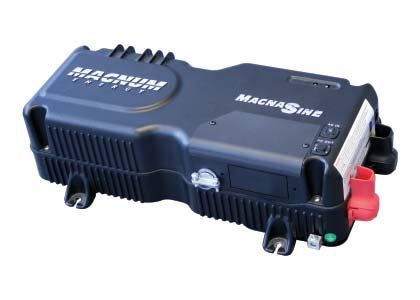
Disclaimer of Liability
The use of this manual and the conditions or methods of installation,
operation, use, and maintenance of the MMS Series Inverter/Charger
are beyond the control of Magnum Energy, Inc. Therefore, this company
assumes no responsibility and expressly disclaims any liability for
loss, damage, or expense whether direct, indirect, consequential, or
incidental that may arise out of or be in any way connected with such
installation, operation, use, or maintenance.
Due to continuous improvements and product updates, the images
shown in this manual may not exactly match the unit purchased.

Restrictions on Use
The MMS Series Inverter/Charger may only be used in life-support
devices or systems with the express written approval of Magnum
Energy. Failure of the MMS Series Inverter/Charger can reasonably
be expected to cause the failure of that life-support device or system,
or to affect the safety or effectiveness of that device or system. If the
MMS Series Inverter/Charger fails, it is reasonable to assume that
the health of the user or other persons may be endangered.

Contact Information
Magnum Energy, Inc.
2211 West Casino Rd.
Everett, WA 98204
Phone: (425) 353-8833
Fax: (425) 353-8390
Web: www.magnumenergy.com

   Record the unit’s model and serial number in case you need to provide
   this information in the future. It is much easier to record this information
   now, instead of trying to gather it after the unit has been installed.

             Model:                              Serial Number:
         MMS1012                         U1

         MMS1012-G                       U1

Conventions Used in this Manual
Terminology
Shore power or External AC power - refers to alternating current
(AC) provided by the utility electric power grid or from a generator.
Mobile application - refers to inverters used in a recreational vehicle
(RV), boat, or a truck installation.

                                               © 2010 Magnum Energy, Inc.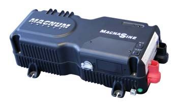
Safety symbols
To reduce the risk of electrical shock, fire, or other safety hazard, the
following safety symbols have been placed throughout this manual
to indicate dangerous and important safety instructions.

             WARNING: This symbol indicates that failure to take a
             specified action could result in physical harm to the user.

             CAUTION: This symbol indicates that failure to take a
             specified action could result in damage to the equipment.

             Info: This symbol indicates information that emphasizes
             or supplements important points of the main text.

    IMPORTANT PRODUCT SAFETY INSTRUCTIONS
This manual contains important safety instructions that must be fol-
lowed during the installation and operation of this product. Read all
instructions and safety information contained in this manual before
installing or using this product.
•    All electrical work must be performed in accordance with local,
     state, and federal electrical codes.
•    This product is designed for indoor/compartment installation. DO
     NOT expose to rain, snow, moisture, or liquids of any type
•    Use insulated tools to reduce the chance of electrical shock or
     accidental short circuits.
•    Remove all jewelry such as rings, watches, bracelets, etc., when
     installing or performing maintenance on the inverter.
•    Always disconnect the batteries or energy source prior to install-
     ing or performing maintenance on the inverter. Live power may
     be present at more than one point since an inverter utilizes both
     batteries and AC. Turning off the inverter may not reduce this
     risk. As long as AC power is connected, it will pass through the
     inverter regardless of the ON/OFF power switch setting.
•    Always verify proper wiring prior to starting the inverter.
•    Do not operate the inverter if it has been damaged.
•    Do not dismantle the inverter; there are no user-serviceable parts
     contained in this product. Attempting to service the unit yourself
     could cause electrical shock. Internal capacitors remain charged
     after all power is disconnected.
•    No AC or DC disconnects are provided as an integral part of this
     inverter. Both AC and DC disconnects must be provided as part
     of the system installation.

    © 2010 Magnum Energy, Inc.                                        i
• No overcurrent protection for the battery supply is provided as an
integral part of this inverter. Overcurrent protection of the battery
cables must be provided as part of the installation.
• No overcurrent protection for the AC output wiring is provided as
an integral part of this inverter. Overcurrent protection of the AC
output wiring must be provided as part of the installation.
IMPORTANT BATTERY SAFETY INSTRUCTIONS
• Wear eye protection (safety glasses) when working with bat-
teries.
• Remove all jewelry such as rings, watches, bracelets, etc., when
installing or performing maintenance on the inverter.
• Never work alone. Always have someone near you when working
around batteries.
• Use proper lifting techniques when working with batteries.
• Never use old or untested batteries. Check each battery’s label for
age, type, and date code to ensure all batteries are identical.
• Batteries are sensitive to changes in temperature. Always install
batteries in a stable environment.
• Install batteries in a well ventilated area. Batteries can produce
explosive gasses. For compartment or enclosure installations,
always vent batteries to the outside.
• Provide at least one inch of air space between batteries to provide
optimum cooling.
• Never smoke when in the vicinity of batteries.
• To prevent a spark at the battery and reduce the chance of ex-
plosion, always connect the cables to the batteries first. Then
connect the cables to the inverter.
• Use insulated tools at all times.
• Always verify proper polarity and voltage before connecting the
batteries to the inverter.
• To reduce the chance of fire or explosion, do not short-circuit
the batteries.
• In the event of accidental exposure to battery acid, wash thor-
oughly with soap and water. In the event of exposure to the eyes,
flood them for at least 15 minutes with running water and seek
immediate medical attention.
• Recycle old batteries.
SAVE ALL INSTRUCTIONS
ii © 2010 Magnum Energy, Inc.Table of Contents
1.0 Introduction ..................................................................1
MMS Series Models ............................................................... 1
How an Inverter/Charger Works ............................................. 2
Inverter Applications for Mobile Installations ............................ 2
Advantages of Pure Sine Wave vs Modified Sine Wave Inverter ... 2
Appliances and Run Time....................................................... 2
Standard Features and Benefits .............................................. 3
Battery Temperature Sensor .............................................. 6
2.0 Installation....................................................................7
Pre-Installation .................................................................... 7
Unpacking and Inspection ...................................................... 7
Locating and Mounting the Inverter ........................................10
Wiring Guidelines ................................................................13
DC Wiring...........................................................................14
DC Wire Sizing and Overcurrent Protection .........................14
DC Overcurrent Protection................................................15
DC Grounding .................................................................16
DC Cable Connections......................................................17
Battery Bank Wiring ............................................................18
Inverter to Battery Bank Wiring ............................................18
DC Ground Wire..............................................................19
DC Negative Wire ............................................................19
Battery Temperature Sensor .............................................19
DC Positive Wire .............................................................19
AC Wiring ...........................................................................20
Neutral to Safety Ground Bonding .....................................20
AC Wiring Connections .....................................................21
AC Wire Size and Overcurrent Protection ............................21
AC Input Wiring ..............................................................22
AC Output Wiring ............................................................24
Ground-Fault Circuit Interruption Breakers .........................25
Functional Test ....................................................................25
3.0 Operation ................................................................... 27
Operating Modes .................................................................27
Inverter Mode.................................................................27
Standby Mode ................................................................28
Protection Circuitry Operation ...............................................32
Inverter Start-up .................................................................33
ON/OFF Switch ...............................................................33
Status LED Indicator .......................................................33
Factory Default Settings .......................................................34
4.0 Maintenance and Troubleshooting ...............................36
Recommended Inverter and Battery Care ...............................36
RV/Marine Off-Season Storage ..............................................36
Resetting the Inverter ..........................................................37
© 2010 Magnum Energy, Inc. iiiTable of Contents
Troubleshooting ..................................................................38
5.0 Specifications ..............................................................39
Appendix A - Optional Equipment and Accessories ............40
Appendix B - Battery Information .....................................41
Battery Bank Sizing .............................................................41
Battery Types .....................................................................41
Battery Configuration ...........................................................41
Series Wiring ..................................................................41
Parallel Wiring ................................................................42
Series-Parallel Wiring.......................................................42
Appendix C - Warranty/Service Information .....................44
Limited Warranty .................................................................44
How to Receive Repair Service ..............................................45
List of Figures
Figure 1, MMS1012 Model Inverter/Charger .............................. 1
Figure 2, MMS1012-G Model Inverter/Charger ........................... 1
Figure 3, Top and Left Side Features ........................................ 4
Figure 4, Front and Back Side Features..................................... 5
Figure 5, Battery Temperature Sensor (BTS) ............................. 6
Figure 6, MMS1012 Model Basic Installation Diagram ................. 8
Figure 7, MMS1012-G Model Basic Installation Diagram .............. 9
Figure 8, Approved Mounting Orientations................................12
Figure 9, MMS1012 Model Inverter/Charger Dimensions ............12
Figure 10, MMS1012-G Model Inverter/Charger Dimensions .......13
Figure 11, DC Cable to Battery Terminals .................................17
Figure 12, DC Cable to Inverter’s DC Terminals .........................17
Figure 13, AC Wiring Connections (MMS1012 model) .................23
Figure 14, AC Hardwiring Connections (MMS1012-G model) .......23
Figure 15, Automatic 4-Stage Charging Graph ..........................30
Figure 16, BTS Temperature to Charge Voltage Change..............31
Figure 17, Resetting the Inverter ............................................37
Figure 18, Series Battery Wiring .............................................41
Figure 19, Parallel Battery Wiring ............................................42
Figure 20, Series-Parallel Battery Wiring ..................................42
Figure 21, Battery Bank Wiring Examples (12-volt) ...................43
List of Tables
Table 1, Recommended DC Wire/Overcurrent Device .................15
Table 2, DC Wire Size For Increased Distance ...........................16
Table 3, Wire Color to AC Wire Connection ...............................21
Table 4, Minimum Wire Size to Circuit-breaker Size ...................22
Table 5, Inverter Battery Turn On/Off Levels.............................33
Table 6, Inverter/Charger Default Settings ...............................35
Table 7, Troubleshooting Guide ...............................................38
Table 8, MMS Series Specifications ..........................................39
iv © 2010 Magnum Energy, Inc.1.0 Introduction
1.0 Introduction
Congratulations on your purchase of an MMS Series inverter/charger
from Magnum Energy, Inc. This product is designed especially for
your mobile application. Powerful, yet simple to use, this product will
provide you with years of trouble-free use.
MMS Series Models
MMS1012 - a 1000 watt inverter/charger with 20 amp AC transfer
capability and a 50 amp, 4-stage Power Factor Correction (PFC)
charger. The AC input and output are provided with pigtail wires to
allow hardwiring to a main AC distribution panel and to an inverter
sub-panel. Features isolated input/output neutrals for mobile
applications. Includes a 15’ battery temperature sensor.
Figure 1, MMS1012 Model Inverter/Charger
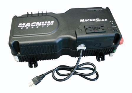
MMS1012-G - a 1000 watt inverter/charger with 20 amp AC transfer
capability and a 50 amp, 4-stage PFC charger. The AC input is
provided by a standard 3 ft. plug-in power cord, and the AC output
is provided by a standard GFCI two plug outlet. Features isolated
input/output neutrals for mobile applications. Includes a 15’ battery
temperature sensor.
Figure 2, MMS1012-G Model Inverter/Charger
© 2010 Magnum Energy, Inc. 11.0 Introduction How an Inverter/Charger Works An inverter takes direct current (DC) from your batteries and turns it into alternating current (AC), like you use at home. With MMS Series models, it also takes alternating current (when connected to a generator or to shore power) and transforms it into direct current to recharge your batteries. The two modes of operation associated with this inverter/charger are referred to in this document as: Inverter Mode: DC from the batteries is transformed into pure sine wave AC for powering your mobile applications. Standby Mode: The unit operates as a battery charger to convert incoming AC power into DC power to recharge the batteries while con- tinuing to pass the incoming AC power directly to the inverter’s output to power any AC loads. Inverter Applications for Mobile Installations Inverters can be used to provide power in mobile situations, such as in an RV, truck, or boat. In these applications, the inverter provides power to the AC loads using the energy stored in the batteries and recharges the batteries when shore power or an onboard generator is available. Advantages of a Pure Sine Wave vs Modified Sine Wave Inverter Today’s inverters come in two basic output waveforms: modified sine wave (which is actually a modified square wave) and pure sine wave. Modified sine wave inverters approximate a pure sine waveform and will run most appliances and electronics without any problems. These inverters are less expensive and, therefore, offer a viable alternative to more expensive pure sine wave inverters. The output of a pure sine wave inverter is equal to or, in many cases, better than the shore power used in your home. Virtually any electronic device will operate from a pure sine wave inverter. Motors run cooler, microwaves usually cook faster, and clocks keep better time just to name a few examples. Without compromising quality or performance, the MagnaSine provides you with all of the advantages of a pure sine wave inverter at a much lower cost than many on the market. Appliances and Run Time The MMS Series inverter/charger can power a wide range of household appliances. As with any appliance using batteries for power, there is a certain length of time that it can run – this is called “run time”. Actual run time depends on several variables including the size and the type of appliance, the type of batteries installed in your applica- tion, as well as the battery’s capacity and age. Other factors such as the battery’s state of charge and temperature can also affect the length of time your appliances can run. 2 © 2010 Magnum Energy, Inc.
1.0 Introduction
Depending on your inverter capacity, larger electrical appliances such
as coffee pots and hair dryers can be used for short durations. How-
ever, loads that are used for longer periods such as stoves or water
heaters can quickly drain your batteries and are not recommended
for inverter applications.
All electrical appliances are rated by the amount of power they
consume. The rating is printed on the product’s nameplate label,
usually located on its chassis near the AC power cord. Even though
it is difficult to calculate exactly how long an inverter will run a par-
ticular appliance, the best advice is trial and error. Your MMS Series
inverter/charger has a built-in safeguard that automatically protects
your batteries from being over-discharged.
Standard Features and Benefits
The MMS Series inverter/charger converts 12 volts of direct current
(VDC) power from your battery to 120 volts alternating current (VAC)
power. The multi-stage battery charger optimizes incoming AC power
using Power Factor Correction (PFC) technology to keep the inverter’s
battery bank fully charged. This inverter is designed to allow easy
installation and use, and with its die-cast aluminum baseplate it en-
sures maximum durability and cooler, more efficient operation.
The inverter/charger provides the following:
•     1000 watts continuous at 25°C.
•     Numerous protection features to provide a safe and peace-of-
      mind operation.
•     AC transfer switch circuitry; allowing incoming AC power to con-
      tinue to pass-thru to power loads even if the inverter is off.
•     Dead battery charging for batteries that are extremely low.
•     Automatic 4-stage battery charger with power factor correction
      and temperature compensation – for optimum battery charging
      (using the temperature sensor).
•     Modern and aesthetically pleasing design with large AC wiring
      compartment (provides easy access to AC wiring for simple and
      quick connections) and 360° DC connection terminals with color
      coded insulating covers.
•     True RMS output voltage regulation to ensure the inverter will
      deliver the correct amount of power – within the DC input voltage
      range and the continuous output power level.
•     Quick connection accessory and remote ports – easily accept
      several optional remote controls and the Battery Temperature
      Sensor.

    © 2010 Magnum Energy, Inc.                                       3
1.0 Introduction
1 2
12 5
3
8 6
4
11
10 9
7
Figure 3, Top and Left Side Features
1. Inverter Status Indicator - this green LED illuminates to provide
information on the inverter’s operation.
2. Power Switch - momentary pushbutton switch that turns the
inverter on or off.
3. Negative DC Terminal (black) - the inverter’s connection to the
negative terminal on the battery bank.
4. Positive DC Terminal (red) - the inverter’s connection to the
positive terminal on the battery bank.
5. Input Circuit Breaker - this circuit breaker protects the unit’s
internal wiring and pass-thru relay.
6. Output Circuit Breaker - this circuit breaker provides another
layer of overload protection. Not a branch circuit-rated breaker.
Separate AC output breakers may be required on the output.
7. Mounting Flanges (x4) - secures the inverter to shelf/wall.
8. AC Wiring Compartment - provides access for all AC input and
output connections on the inverter.
9. AC Output Connection - AC knockout for hardwiring AC
output.
10. AC Input Connection - Strain relief clamp for hardwiring AC
input. Strain relief comes with an attached flexible AC input power
cord on the MMS1012- G model.
11. DC Ground Terminal - this connection is used to tie the exposed
chassis of the inverter to the DC grounding system. This terminal
accepts CU/AL conductors from #14 AWG to #6 AWG.
12. GFCI Outlet - Ground Fault Circuit Interrupter outlet (with test
and reset capability). Only available on MMS1012-G model.
4 © 2010 Magnum Energy, Inc.1.0 Introduction
Front Side
13
14
15
16
Back Side
17
18
Figure 4, Front and Back Side Features
13. Warning and Information Label - provides pertinent
information for safely using the inverter.
14. REMOTE Port Connection - a RJ11 connector that allows an
optional remote control to be connected.
15. ACCESSORY PORT Connection - a RJ11 connector to allow the
Battery Temperature Sensor (BTS) or MMS accessories (e.g., MM-
DCLD, MM-ISA) to be connected.
16. Intake Vent - ventilation openings to pull in air to keep the
inverter cool for peak performance.
17. Exhaust Vent - ventilation openings that allow heated air to be
removed by the internal cooling fan.
18. Model/Serial Number Label - includes model/serial number and
provides specifications and information on the inverter and charger.
See the MMS Series Specifications on page 38 for more informa-
tion and the different models available.
© 2010 Magnum Energy, Inc. 51.0 Introduction
Battery Temperature Sensor
A plug-in external Battery Temperature Sensor (BTS) is provided
for units with the battery charger feature. When installed, the BTS
automatically adjusts the battery charger’s BULK, ABSORB, and
FLOAT voltage set-points (based on temperature) for better charging
performance and longer battery life. If the temperature sensor is
NOT installed and the batteries are subjected to large temperature
changes, battery life may be shortened.
~2 " ~ 1"
F R O N T V IE W
~¾ ”
Ca b le 0 .3 7 5" d ia m e te r
S ID E V IE W ~½ ”
Figure 5, Battery Temperature Sensor (BTS)
6 © 2010 Magnum Energy, Inc.2.0 Installation
2.0 Installation
Pre-Installation
Before installing the inverter, read the entire Installation section. The
more thorough you plan in the beginning, the better your inverter
needs will be met.
WARNING: Installations should be performed by qualified
personnel, such as a licensed or certified electrician. It
is the installer’s responsibility to determine which safety
codes apply and to ensure that all applicable installation
requirements are followed. Applicable installation codes
vary depending on the specific location and the type of
installation.
Info: Review the “Important Product Safety Information”
on page ii and the “Important Battery Safety Instructions”
on page iii before any installation.
The basic system diagrams shown in Figures 6 and 7 should be
reviewed to assist you in planning and designing your installation.
Unpacking and Inspection
Carefully remove the MMS Series inverter/charger from its shipping
container and inspect all contents. Verify the following items are
included:
− MMS Series inverter/charger
− Red and black DC terminal covers
− AC access cover with two screws
− Two 1/2” hex-head kep nuts (installed on the DC terminals)
− Battery Temperature Sensor (BTS)
− MMS Series Owner’s Manual
If items appear to be missing or damaged, contact your authorized
Magnum Energy dealer or Magnum Energy.
If at all possible, keep your shipping box. It will help protect your
inverter from damage if it ever needs to be returned for service.
Save your proof-of-purchase as a record of your ownership; it will
also be needed if the unit should require in-warranty service.
Record the unit’s model and serial number in the front of this manual
in case you need to provide this information in the future. It is much
easier to record this information now, instead of trying to gather it
after the unit has been installed.
© 2010 Magnum Energy, Inc. 7Installation
AC
M a in P a n e l
A C IN
DC
AC Ground
OU T
DC
AC d isco n n e ct
S u b -P a n e l and
(o p tio n a l) o ve rcu rre n t
d e vice
AC
O utlet
B attery
B ank
TV T ools
VC R
A C Loads
Figure 6, MMS1012 Model Basic Installation Diagram
8 © 2010 Magnum Energy, Inc.Installation
DC
A C IN Ground
AC
OU T DC
d isco n n e ct
and
o ve rcu rre n t
A C Loads d e vice
TV T ools
VC R
B attery
B ank
Figure 7, MMS1012-G Model Basic Installation Diagram
© 2010 Magnum Energy, Inc. 92.0 Installation
Locating and Mounting the Inverter
WARNINGS:
• Do not mount the inverter near any flammable or
combustible fluid or components.
• Provide adequate clearance/ventilation to the inverter.
• Mount only on a non-combustible surface.
• Maximum ambient temperature around the inverter must
not exceed 77° F (25° C) to meet power specifications.
The inverter should only be installed in a location that meets the
following requirements:
Clean and Dry - The inverter should not be installed in an area that
allows dust, fumes, insects, or rodents to enter or block the inverter’s
ventilation openings. The area also must be free from any risk of
condensation, water, or any other liquid that can enter or fall on the
inverter. The inverter uses stainless steel fasteners, plated copper
busbars, and a power-coated aluminum base. Also, the internal circuit
boards are conformal coated. The above measures are undertaken
to help fight the harmful effects of corrosive environments. However,
the life of the inverter is uncertain if used in any of these types of
environments, and inverter failure under these conditions is not covered
under warranty.
Cool - The inverter should be protected from direct exposure to the
sun or any equipment that produces extreme heat. The ambient air
temperature should be between 32° F (0° C) and 104° F (40° C);
keep in mind that the inverter’s output specifications are rated at 77°
F (25° C), so the cooler the better within this range.
Ventilated - In order for the inverter to provide full output power
and avoid over-temperature fault conditions do not cover or block
the inverter’s ventilation openings, or install this inverter in an area
with limited airflow. Allow as much clearance around the inverter’s
intake and exhaust ventilation openings as possible, see Items 16
and 17 in Figure 4. At the minimum, allow an airspace clearance of
6” (15 cm) at the front and back, and 3” (7.5 cm) everywhere else
to provide adequate ventilation.
If installed in an enclosure, a fresh air intake opening must be pro-
vided directly to the front side (intake vent) and an exhaust open-
ing on the back side (exhaust vent) of the inverter. This will allow
cool air from the outside to flow into the inverter, and heated air to
exit away from the inverter and the enclosure. When mounted in an
enclosed compartment, airflow must be at least 59 cfm in order to
maintain no more than a 68° F (20° C) rise in compartment tem-
perature. Minimum clearances can be reduced if airflow is increased,
but in no case should clearance around the inverter be less than 2”
(5 cm) on all sides.
10 © 2010 Magnum Energy, Inc.2.0 Installation
Safe - Keep any flammable/combustible material (e.g., paper, cloth,
plastic, etc.) that may be ignited by heat, sparks, or flames at a
minimum distance of 2 feet (60 cm) away from the inverter.
WARNING: The MMS Series Inverter/Charger is not
an ignition-protection rated device and should not be
installed in any location that requires ignition-protected
equipment. To prevent fire or explosion, do not install
the MMS Series in any area with extremely flammable
liquids like gasoline or propane; or, in an area that
contains connections between components of a fuel
system.
Close to the battery bank - As with any inverter, it should be
located as close to the batteries as possible. Long DC wires tend to
lose efficiency and reduce the overall performance of an inverter.
However, the unit should not be installed in the same compartment as
the batteries or mounted where it will be exposed to gases produced
by the batteries. These gases are corrosive and will damage the
inverter. Also, if these gases are not ventilated and allowed to collect,
they could ignite and cause an explosion.
Accessible - Do not block access to the inverter’s remote control
and accessory ports. Also, allow enough room to access the AC
and DC wiring connections, as they will need to be checked and
tightened periodically. See Figure 9 & 10 for the MMS Series’ inverter
dimensions.
Mounting Orientation - To meet regulatory requirements, the MMS
Series inverter/charger can only be mounted on a horizontal surface
(shelf or table) or a vertical surface (wall or bulkhead) either right-
side up or upside-down, as shown in Figure 8. The inverter must be
mounted on a non-combustible surface, and this surface and the
mounting hardware must be capable of supporting at least twice the
weight of the inverter. After determining your mounting position,
use the base of the inverter’s chassis as a template to mark your
mounting screw locations. Remove the inverter and drill pilot holes
into the mounting surface.
If this unit is used in a mobile application, you may want to place
flexible washers or bushings between the mounting surface and the
inverter’s mounting flanges to reduce vibration.
After the inverter has been properly mounted, proceed to the DC
Wiring section.
© 2010 Magnum Energy, Inc. 112.0 Installation
Wall Mounted (right-side up)
Shelf Mounted
(right-side up)
Shelf Mounted
(up-side down)
Wall Mounted (up-side down)
Figure 8, Approved MMS1012 (-G) Mounting Orientations
M ounting holes x 4
~ 4 ⅝"
[¼ ” ( 0.25 ") diam eter ]
( 4.625 ")
~ 16 5/8 " 10 .0"
(16 .59 ")
~6 3/4 " (6.71")
~ 7 ½ " (7.51")
~ 8 7 /16 " (8.41 ")
Figure 9, MMS1012 Model Inverter/Charger Dimensions
12 © 2010 Magnum Energy, Inc.2.0 Installation
M ounting holes x 4
[¼” (0.25") diameter] ~ 4 ⅝”
(4.625 ")
10 "
~ 16 5 /8 "
(16.59 ")
~ 6 ¾ ” (6.71 ") ~ 5"
~ 7 ½ ” (7.51 ") ~ 5 ⅛"
(5.125 ")
~8 7/16 ” (8 .41 ")
Figure 10, MMS1012-G Model Inverter/Charger Dimensions
Wiring Guidelines
• Before connecting any wires, determine all wire routes to and
from the inverter throughout the RV, vehicle, or boat.
• Conductors passing through walls or other structural members
must be protected to minimize insulation damage such as chafing,
which can be caused by vibration or constant rubbing.
• Always check for existing electrical, plumbing, or other areas of
potential damage prior to making cuts in structural surfaces or
walls.
• Make sure all wires have a smooth bend radius and do not be-
come kinked.
• Both AC and DC overcurrent protection must be provided as part
of the installation.
© 2010 Magnum Energy, Inc. 132.0 Installation
• Do not attempt to use a vehicle metal frame in place of the nega-
tive connection or DC ground. The inverter requires a reliable
negative and ground return path directly to the battery.
• DC wires and cables should be tied together with wire ties or
electrical tape approximately every 6 inches. This helps improve
the surge capability and reduces the effects of inductance,
which improves the inverter waveform and reduces wear on the
inverter’s filter capacitors.
• Use only copper wires with a minimum temperature rating of
75°C.
• To ensure the maximum performance from the inverter, all con-
nections from the battery bank to the inverter should be mini-
mized; the exceptions are the DC overcurrent disconnect in the
positive line.
DC Wiring
This section describes the MMS Series inverter’s required DC wire sizes
and the recommended disconnect/overcurrent protection, and how to
make the DC connections to the inverter and the battery bank.
DC Wire Sizing and Overcurrent Protection
It is important to use the correct DC wire to achieve maximum ef-
ficiency from the system and reduce fire hazards associated with
overheating. See Table 1 to select the minimum DC wire size needed
based on your inverter model. If the distance from the inverter to the
battery bank is greater than 3 feet, use Table 2 to help determine
the minimum recommended cable sizes for longer distances. Always
keep your wire runs as short as practical to help prevent low voltage
shutdowns, and keep the DC breaker from nuisance tripping (or open
fuses) because of increased current draw. Undersized cables can also
lower the inverter’s peak output voltage, as well as reduce its ability
to surge heavy loads.
Info: The DC wires must be color coded with colored
tape or heat shrink tubing; RED for positive (+), BLACK
for negative (-), and GREEN for DC ground.
The DC wires must have soldered and crimped lugs, crimped copper
compression lugs, or aluminum mechanical lugs. Soldered connec-
tions alone are not acceptable for this application.
14 © 2010 Magnum Energy, Inc.2.0 Installation
Table 1, Recommended DC Wire/Overcurrent Device
Inverter Model
MMS1012 MMS1012-G
Maximum Continuous
200 amps 200 amps
Current¹
DC Grounding
# 6 AWG # 6 AWG
Electrode Wire Size
Minimum DC Wire Size # 1/0 AWG # 1/0 AWG
(90˚C rating in free air) (260 amps) (260 amps)
Maximum DC 300 amps with 300 amps with
Fuse Size time delay time delay
Info: The term “in free air” is defined by the NEC as not
encased in conduit or raceway.
If the inverter is expected to operate at a distance greater than
three feet from the battery bank, the DC wire size will need to be
increased to overcome the increase in resistance – which affects the
performance of the inverter. Continue to use the overcurrent device
and DC ground wire previously determined from Table 1 and then,
refer to Table 2 to determine the minimum DC wire size you need for
various distances based on your inverter model.
DC Overcurrent Protection
For safety and to comply with NEC (National Electrical Code) electrical
code regulations, you must install a DC overcurrent protection device
in the positive DC cable line to protect your DC cables. This DC
overcurrent device can be a fuse or circuit-breaker, but must be DC
rated. It must be correctly sized according to the size of DC cables
being used, which means it is required to open before the cable
reaches its maximum current carrying capability, thereby preventing
a fire. See Table 1 to select the DC overcurrent device based on the
minimum wire size for your inverter model.
Note 1 - Maximum Continuous Current is based on the inverter’s continuous
power rating at the lowest input voltage with an inefficiency factor.
Note 2 - Per the NEC, the DC grounding electrode conductor can be a #6 AWG
conductor if that is the only connection to the grounding electrode and that
grounding electrode is a pipe, rod, or plate electrode.
Note 3 - Wire size is based on the requirements needed to increase efficiency
and reduce stress to the inverter.
Note 4 - The next larger standard size overcurrent device may be used if
the de-rated cable ampacity falls between the standard overcurrent devices
found in the NEC.
© 2010 Magnum Energy, Inc. 152.0 Installation
Table 2, DC Wire Size For Increased Distance
Minimum recommended DC wire size (one way)
3 ft or less 3 to 5 ft 5 to 10 ft 10 to 15 ft
MMS1012 #1/0 AWG #1/0 AWG #2/0 AWG #4/0 AWG
MMS1012-G # 1/0 AWG #1/0 AWG #2/0 AWG #4/0 AWG
Electrical systems in mobile installations typically do not require using
a DC disconnect, although an overcurrent protection device is still
required. Because the DC disconnect is not required, a fuse is usually
used as the disconnect device in these installations. These installations
also do not normally use conduit, so the fuse must be installed in the
ungrounded conductor (usually the positive DC cable line) within 18
inches of the battery – to protect the DC wiring system.
If using a fuse, we recommend using a class-T type or equivalent.
This fuse type is rated for DC operation, can handle the high short-
circuit currents, and allows for momentary current surges from the
inverter without opening.
DC Grounding
The inverter/charger should always be connected to a permanent,
grounded wiring system. The idea is to connect the metallic chassis
of the various enclosures together to have them at the same voltage
potential, which reduces the possibility for electric shock. For the
majority of installations, the inverter chassis and the negative battery
conductor are connected to the system’s ground bond via a safety-
grounding conductor (bare wire or green insulated wire) at only one
point in the system. Per the NEC, the size for the grounding conductor
is usually based on the size of the overcurrent device used in the DC
system. Refer to Table 1 to select the appropriate DC ground wire
based on the overcurrent device used for your inverter model.
If the inverter is in a vehicle, DO NOT connect the battery negative
(-) cable to the vehicle’s safety ground. Only connect to the inverter’s
negative battery terminal. If there are any non-factory installed
appliances onboard the vehicle, DO NOT ground them at safety
ground. Only ground them at the negative bus of the DC load center
(as applicable).
16 © 2010 Magnum Energy, Inc.2.0 Installation
DC Cable Connections
When connecting the DC cable to the battery or to the inverter’s DC
terminals, the hardware should be installed in the correct order to
prevent high resistance connections from heating up and possibly
causing the connections to melt. Follow Figures 11 and 12 to stack
the hardware correctly. Tighten the terminal connections from 10 to
12 foot-pounds.
CAUTION: Don’t put anything between the DC cable ring
lug and the battery terminal post or the inverter’s DC
terminal. If antioxidant grease or spray is used, apply it
after all the connections have been made and are properly
tightened.
CAUTION: Overtightening or misthreading nuts on the DC
terminals will cause the bolts to strip and snap/break-off.
T em perature sensor
nut D C cable
w ith ring lug
lock w asher
B A T T ER Y
battery term inal
flat w asher Verify that the
bolt DC cable lugs are flush
battery with the battery terminals.
post T orque the battery terminals
from 10 to 12 foot-pounds.
Figure 11, DC Cable to Battery Terminals
CAUTION: The inverter is NOT reverse polarity protected
(negative and positive connected backwards). You must
verify the correct voltage polarity BEFORE connecting the
DC wires or damage may occur.
Crimped and sealed copper ring terminal lugs with a 5/16” hole should
be used to connect the DC wires to the inverter’s DC terminals.
D C cable
w ith ring lug
DC
term inal cover
(snaps on)
Inverter’s
D C term inal
5 /16 ” (Kep
nut w ith star-w asher) or
F lange nut
Figure 12, DC Cable to Inverter’s DC Terminals
© 2010 Magnum Energy, Inc. 172.0 Installation
Battery Bank Wiring
WARNING: Lethal currents will be present if the positive
and negative cables attached to the battery bank touch each
other. During the installation and wiring process, ensure
the cable ends are insulated or covered to prevent touch-
ing/shorting the cables.
Info: DO NOT connect the DC wires from the battery bank
to the inverter until: 1) all DC/AC wiring is complete, 2)
the correct DC and AC overcurrent protection have been
installed, and 3) the correct DC voltage and polarity have
been verified.
Info: For optimum performance, a minimum battery bank
of 200 AHr is recommended.
Depending upon the type of batteries you use in the installation (6
or 12 VDC), the batteries must be wired in series, parallel, or series-
parallel (see Appendix B - Battery Information, for guidance on wiring
batteries together). The interconnecting DC wires must be sized and
rated exactly the same as those that are used between the battery
bank and the inverter.
Place the batteries as close as practical to the inverter, preferably in
an insulated and ventilated enclosure. Allow adequate space above
the batteries to access the terminals and vent caps (as applicable).
Also, allow at least 1” of space between the batteries to provide good
air flow. DO NOT mount the batteries directly under the inverter.
Info: To ensure the best performance from your inverter
system do not use old or untested batteries. Batteries
should be of the same size, type, rating, and age.
CAUTION: Install batteries in a well ventilated area. Bat-
teries can produce explosive gasses. For compartment
or enclosure installations, always vent batteries to the
outside.
Inverter to Battery Bank Wiring
WARNING: Ensure all sources of DC power (i.e., bat-
teries) and AC power (shore power or AC generator) are
de-energized (i.e., breakers opened, fuses removed)
before proceeding.
18 © 2010 Magnum Energy, Inc.2.0 Installation
CAUTION: The inverter is NOT reverse polarity pro-
tected. If this happens, the inverter will be damaged and
will not be covered under warranty. Before connecting
the DC wires from the batteries to the inverter, verify
the correct battery voltage and polarity using a voltme-
ter. If the positive terminal of the battery is connected
to the negative terminal of the inverter and vice versa,
severe damage will result. If necessary, color code the
cables with colored tape or heat shrink tubing; RED for
positive (+), and BLACK for negative (-) to avoid polar-
ity confusion.
Info: The DC overcurrent device (i.e., fuse or circuit
breaker) must be placed in the positive (RED) DC cable
line between the inverter’s positive DC terminal and
the battery’s positive terminal (RED); as close to the
battery as possible.
DC Ground Wire
Route an appropriately sized DC grounding wire (GREEN or bare wire)
from the inverter’s DC Ground Terminal (see Figure 3, Item 11) to a
dedicated system ground. Recommended tightening torque is 45 in.
lbs.
DC Negative Wire
Route an appropriately sized DC negative wire (BLACK) from the
negative terminal of the first battery string to the inverter’s negative
terminal (see Figure 21 for reference).
Battery Temperature Sensor
Connect the RJ11 connector end of the BTS to the ACCESSORY PORT
(see Figure 4, Item 15) on the inverter. Connect the other end of the
BTS to the negative terminal of the first battery string (in same place as
the negative DC wire above); refer to Figure 11 for the correct hardware
placement.
DC Positive Wire
Mount the DC fuse block and disconnect (or circuit breaker assembly)
as near as practical to the batteries, and then open the disconnect
(or circuit breaker).
WARNING: DO NOT close the DC fuse/DC disconnect (or
close the DC circuit breaker) to enable battery power to
the inverter at this time. This will occur in the Functional
Test after the installation is complete.
Route and connect an appropriately sized DC positive wire (RED) from
the DC fuse block (or circuit breaker assembly) to the inverter’s posi-
tive DC terminal.
© 2010 Magnum Energy, Inc. 192.0 Installation
Connect a short wire (same rating as the DC wires) to one end of the
fuse block and the other end of the short wire to the positive terminal
of the last battery string (see Figure 21). This is essential to ensure
even charging and discharging across the entire battery bank.
Ensure the DC wire connections (to batteries, inverter, and fuse lugs/DC
circuit breaker) are flush on the surface of the DC terminals, and the
hardware (lock washer and nut) used to hold these connections are
stacked correctly (see Figures 11 and 12).
Verify all DC connections are torqued from 10 to 12 foot-pounds.
Once the DC connections are completely wired and tested, coat the
terminals with an approved anti-oxidizing spray.
Press the red and black terminal covers onto the inverter’s DC con-
nectors to secure them in place.
If batteries are in an enclosure, perform a final check of the hold
down brackets and all connections. Close and secure the battery
enclosure.
AC Wiring
This section describes the MMS Series’ required AC wire size and
overcurrent protection. It also provides information on how to make
the AC connections.
Info: The MMS1012-G model has a power cord for
AC input and dual outlets on top of the inverter for AC
output, however, it has hardwiring capability as well.
WARNING: All wiring should be done by a qualified
person or a licensed electrician following all local/NEC
codes.
Neutral to Safety Ground Bonding
The NEC (National Electric Code)/CEC (Canadian Electrical Code)
provide the standards for safely wiring mobile (RV, boat, or truck)
installations. These wiring standards require the AC source (inverter,
shore power, or a generator) to have the neutral conductor tied to
ground. These standards also require that the AC neutral be con-
nected to safety ground (often called a “bond”) in only one place at
any time. If more than one bond is established, currents can circulate
between neutral and ground and cause ground-loop currents. These
“ground-loops” can trip GFCIs and cause an electric shock hazard.
In mobile installations, there may be multiple AC sources (i.e., shore
power, generator, or inverter), which means there may be the poten-
tial of having multiple neutral to ground connections.
20 © 2010 Magnum Energy, Inc.2.0 Installation
AC Wiring Connections
For the MMS1012 model, the AC input and output wiring is performed
in the AC wiring compartment. This compartment is accessed via
the top panel (see Figure 3, Item 8). If the panel cover is installed,
remove the two Phillips screws on the cover to access the AC wiring
compartment and locate the inverter’s AC wiring. There is a label
located in the AC access compartment which gives information on
which wires are used for AC input and output. You can also refer to
Table 3 to match the inverter’s AC wires to the appropriate AC wire
connection.
Table 3, Wire Color to AC Wire Connection
Wire color (label) Wire connection
Black (HOT IN) Hot In
AC IN
White (NEUT IN) Neutral In
Red (HOT OUT) Hot Out
AC OUT White with black
Neutral Out
stripe (NEUT OUT)
AC Ground Green (GROUND) AC IN and AC OUT Ground
The AC wires inside the AC compartment are #16 AWG with a tem-
perature rating of 105° C. All AC connections should be made using
an approved connector for your application (e.g., split bolt, twist-on
wire connectors, etc.). Ensure the wire connectors used are rated for
the size and number of wires you are connecting.
After connecting the wires together, gently pull on the wires to ensure
they are securely held together. In a proper connection, no bare wire
should be exposed.
Info: Per UL certification, non-metallic sheathed cable
(i.e., Romex™) or an SO flexible cord with listed strain
reliefs are allowed to be used to connect to the inverter;
conduit connections are not allowed.
After all AC wiring in the inverter is complete (and before reattaching
the AC access cover), ensure all connections are correct and secure.
AC Wire Size and Overcurrent Protection
The AC input and output wiring must be sized per the NEC and local
electrical safety code requirements to ensure the wire’s ability to
safely handle the inverter’s maximum load current. After determining
the proper AC wire sizes, the inverter’s AC input (unless you are using
a flexible cord) and output wires are required to be protected against
overcurrent and have a means to disconnect the AC circuits.
© 2010 Magnum Energy, Inc. 212.0 Installation
All inverter AC input and output wiring is required to be protected by an
overcurrent protection device. Overcurrent protection must be provided
by fuses or circuit-breakers, and must be properly sized and rated for
the wire they are protecting and the appliances being powered.
Most inverter’s that are hardwired use a service/distribution panel
wired to the inverter’s input (main panel), and a dedicated panel
between the inverter’s output wiring and the AC loads (sub-panel).
These systems use the circuit breakers provided in the panels as the
overcurrent protection and the AC disconnect. If fuses are used, then
separate AC disconnect switches will be needed.
Based on information from the NEC, Table 4 provides the minimum
AC wire size and the suggested breaker size based on the inverter
model. However, a larger wire size may be required because of volt-
age drop. The AC wire sizes provided in this table assume using only
copper wire and a temperature rating of 75° C or higher. A minimum
of #14 AWG is required for all AC wiring.
Table 4, Minimum Wire Size to Circuit-breaker Size
AC Input AC Output
Inverter Minimum Suggested Minimum Suggested
Model Input Output
Wire Breaker Wire Breaker
Breaker Breaker
Size Size Size Size
MMS1012 20 amps #12 AWG 20 amps 15 amps #14 AWG 15 amps
MMS1012
20 amps #12 AWG 20 amps 15 amps #14 AWG 15 amps
-G
AC Input Wiring
Your inverter has an AC transfer feature that passes the AC input
power to the inverter’s output. Connection to the AC input is made
by hardwiring from a distribution panel as described below:
1. Run an appropriately sized 2-conductor plus ground cable (from
the AC distribution panel) through the strain relief clamp on the AC
IN opening (Figure 3, Item 10). Refer to Table 4 for minimum wire
size and overcurrent protection required for the AC input wiring.
2. Remove about two inches of the insulating jacket from the AC
cable, and then separate the three wires and strip about 3/4” of
insulation from each wire.
3. Using approved AC wire connectors, connect the incoming Hot
In, Neutral In, and Ground wires to the MMS Series’ AC wires
colored black (HOT IN), white (NEU IN), and green (AC GROUND)
respectively.
4. After making the AC input connections, secure the AC input cable
by tightening the strain relief clamp.
The AC input wiring in the inverter is complete. Review all AC wiring
to ensure all connections are correct and secure.
22 © 2010 Magnum Energy, Inc.2.0 Installation
AC
G ro u n d N e u tra l O u t
N e u tra l (w h ite w/ b la ck
In (w h ite) In /O u t strip e )
(g re e n)
H ot H ot
In Out
(b la ck) (re d)
Strain
reliefs
AC IN AC O UT
Figure 13, AC Wiring Connections (MMS1012 model)
H ot
H ot Out
(re d)
In
(b la ck)
N e u tra l
O u t (w h ite
N e u tra l w/ b la ck strip e)
In (w h ite)
AC
AC Strain G ro u n d
reliefs
G ro u n d O u t (g re e n)
In (g re e n)
AC IN AC O UT
Figure 14, AC Hardwiring Connections (MMS1012-G model)
Info: The MMS1012-G model has a power cord for AC
input and a factory-installed dual outlet on top of the
inverter for AC output.
© 2010 Magnum Energy, Inc. 232.0 Installation
AC Output Wiring
CAUTION: The inverter’s AC output must never be con-
nected to an AC power source. This will cause severe
damage to the inverter and is not covered under war-
ranty.
Info: When using the MMS Series inverter in an RV ap-
plication, under certain conditions and provided that the
wire is properly sized for the protecting breaker; RVIA
wiring standards will permit the breaker in the Main dis-
tribution panel and/or the supplemental breakers on the
inverter to provide adequate protection for the AC output
wiring. For more information on these requirements, refer
to the RVIA (www.rvia.org).
Follow the steps below to hardwire the AC output of the MMS Series
inverter:
1. Remove the 1/2” knockout on the AC Output Connection (see Figure
3, Item 9) – use a utility knife to cut thru the round slot.
2. Discard this knockout and install a 1/2” strain relief in the AC OUT
opening. You may need to file the opening edge for proper fit.
3. Run a 2-conductor plus ground cable through the strain relief in
the AC OUT opening. Refer to Table 4 for the minimum wire size and
the overcurrent protection required for the AC output wiring.
4. Remove about two inches of the insulating jacket from the AC
cable, and then separate the three wires and strip about 3/4” of
insulation from each wire.
5. Using approved AC wire connectors, connect the outgoing Hot
Out, Neutral Out, and AC Ground wires to the inverter’s AC wires
colored red (HOT OUT), white with black stripe (NEU OUT), and
green (AC GROUND) respectively. Gently pull on the wires to ensure
they are securely held together, and check to see that no bare wire
is exposed.
6. After making the AC output connections, secure the AC output
cable by tightening the strain relief.
7. Connect the outgoing AC wires to either:
a. an AC load sub-panel equipped with overcurrent protection
(e.g., circuit breakers), or
b. directly to the circuit, when following RVIA requirements that
permit using breakers from the main distribution panel or the
breakers on the inverter under certain conditions.
The AC output wiring in the inverter should be complete. Before
reattaching the AC access cover, review all AC wiring to ensure all
connections are correct and secure.
24 © 2010 Magnum Energy, Inc.2.0 Installation
Ground-Fault Circuit Interruption (GFCI) Breakers
If installing this inverter in the wiring system of a mobile application
(RV, boat, or truck), a Ground Fault Circuit Interrupter (GFCI) must
be installed to protect all branch circuits powered by this inverter. In
compliance with UL standards, Magnum Energy tested the following
GFCIs and found that they function properly when connected to the
inverter’s AC output.
Shock SentryTM #XGF15V-SP
Leviton Smart Lock #8899-A
Hubbel #GF520EMBKA
WARNING: Risk of electric shock. Use only the GF-
CIs [receptacles or circuit breaker(s)] specified in this
manual. Other types may fail to operate properly when
connected to this inverter.
Functional Test
After all electrical connections to the inverter, batteries, AC source,
and loads (using a sub-panel) have been completed, follow these
steps to test the installation and the inverter’s operation.
1. Check the battery voltage and polarity before connecting the bat-
teries to the inverter. Use a multimeter to verify 10 to 14 VDC at the
batteries’ positive and negative terminals.
2. Apply battery power to the inverter by switching the DC disconnect
ON (or close the DC circuit-breaker). The inverter will remain OFF,
but the green status indicator on the front of the inverter will quickly
blink once to indicate that DC power has been connected and is ready
to be turned on.
3. Prior to turning on the inverter, make sure all connected loads (e.g.,
appliances) are switched OFF or disconnected from the AC outlets.
4. a. If a remote switch is connected, press the ON/OFF switch to
turn the inverter on.
b. If there is not a remote switch connected, lightly press and
release the inverter’s ON/OFF power switch — located on the top of
the inverter — to turn the inverter on.
Verify the inverter’s status indicator is blinking – indicating the in-
verter is providing AC power.
5. Check the output voltage of the inverter by connecting a true RMS
multimeter to the outlets powered by the inverter. Verify the voltage
is 120 VAC +/- 5 VAC. If not using a true RMS meter the output AC
voltage could indicate from 90 to 130 VAC, depending on the bat-
tery voltage.
© 2010 Magnum Energy, Inc. 252.0 Installation 6. Turn on or connect a load to the outlets and verify it comes on. Continue to keep the load connected and turned on. 7. Press the remote ON/OFF switch to turn the inverter off. If the remote is not used, press and release the inverter’s ON/OFF power switch to turn the inverter off. The inverter’s status indicator and the connected load should go off. 8. Apply AC power to the inverter’s AC input. After the AC input power is qualified (approximately 15 seconds), the incoming AC power will transfer through the inverter to the inverter’s AC output and power the connected load. Verify the inverter’s status indicator and the connected load comes on. 9. Even though the connected load is on, the inverter is currently disabled/off. Press the remote’s ON/OFF switch (or press and re- lease the ON/OFF power switch on the inverter) to enable/turn on the inverter. 10. Disconnect the incoming AC power to the inverter. Verify the con- nected load remains on, but now is powered by the inverter. If the inverter passes all the steps, the inverter is ready for use. If the inverter fails any of the steps, refer to the Troubleshooting section. 26 © 2010 Magnum Energy, Inc.
You can also read