FR/HP Series Installation, Operation, & Maintenance Instructions - Ruffneck Heaters

Page created by Glen Jensen
 
CONTINUE READING
FR/HP Series Installation, Operation, & Maintenance Instructions - Ruffneck Heaters
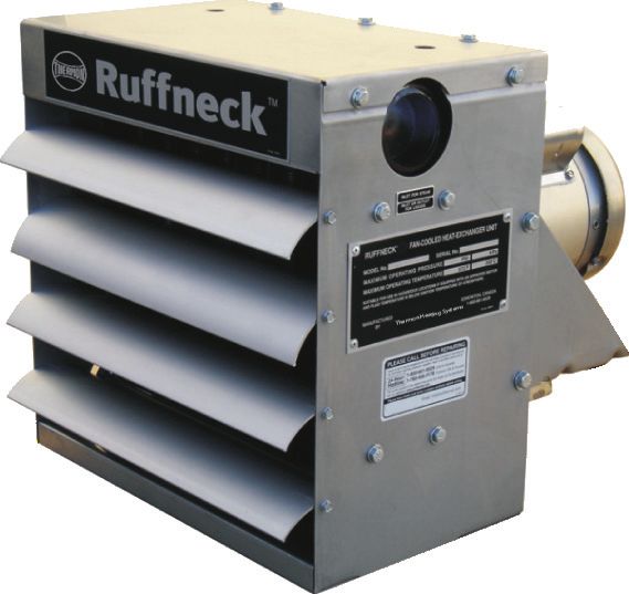
Frost Resistant and High Pressure Heat-Exchanger Unit Heaters

 FR/HP Series
  Installation, Operation, & Maintenance Instructions

           ®
                                 ISO 9001

Approved Locations
The Forced Air Heaters are CSA listed, certified for the following locations:
Class I, Division 1 & 2, Groups C & D; Class II, Division 1 & 2, Groups E, F, & G; Class III,
Division 1 & 2; Temperature Code T3B 329˚F (165˚C) (Applicable Models Only)
For details of hazardous locations with potential for explosion, refer to the Canadian Electrical
Code, Part 1, Section 18 or National Electrical Code articles 500-516.                              Part No.5347.Rev.11.05 Jan 2018   Printed in Canada
TABLE OF CONTENTS
A. Heater Maintenance Checklist                                                                                                   3
    A.1   Periodic���������������������������������������������������������������������������������������������������������������� 3
    A.2   Annual������������������������������������������������������������������������������������������������������������������ 3
B. Important Notices                                                                                                              4
C. Installation                                                                                                                   5
    C.1   Description����������������������������������������������������������������������������������������������������������� 5
    C.2    Location of Heaters���������������������������������������������������������������������������������������������� 5
    C.3    Noise Levels��������������������������������������������������������������������������������������������������������� 5
    C.4   Mounting�������������������������������������������������������������������������������������������������������������� 5
    C.5    Clearances for Maintenance�������������������������������������������������������������������������������� 6
    C.6    Piping Applications����������������������������������������������������������������������������������������������� 6
    C.7    Wiring Schematics����������������������������������������������������������������������������������������������� 7
D. Dimensions & Specifications                                                                                                    9
E. Repair & Replacement Procedures                                                                                              10
    E.1   Cores������������������������������������������������������������������������������������������������������������������ 10
    E.2    Removal of Fan, Fan Guard, or Motor����������������������������������������������������������������� 10
    E.3    FR/HP 36 Fan Guard������������������������������������������������������������������������������������������ 10
    E.4    V-Belt Service: Removal, Installation, & Tensioning��������������������������������������������� 10
    E.5    Fan Motor: Removal & Installation����������������������������������������������������������������������� 10
    E.6    Drive Sheaves: Removal & Installation���������������������������������������������������������������� 10
    E.7    Drive Frame: Removal����������������������������������������������������������������������������������������� 10
    E.8    Fan Shaft Bearings: Removal & Installation��������������������������������������������������������� 10
    E.9    Fan: Removal & Installation��������������������������������������������������������������������������������� 11
F. Parts List                                                                                                                   12
    F.1    FR/HP 12, 16, 20, 24, and 30 Models������������������������������������������������������������������ 12
    F.2    XS40 Disconnect������������������������������������������������������������������������������������������������ 13
    F.3    FR/HP 36 Models����������������������������������������������������������������������������������������������� 14
G. Model Coding                                                                                                                 15

                              Ruffneck™ is a key brand of Thermon Heating Systems, Inc.
                                       Copyright © 2018. All rights reserved.
Photocopy

A.          HEATER MAINTENANCE CHECKLIST                                                                                                        this page
                                                                                                                                               for reuse.

            WARNING. Disconnect heater from the power supply before opening enclosures or servicing heater.
            Lock the switch in the “OFF” (open) position and/or tag the switch to prevent unexpected power application.
  WARNING
            For heaters marked "IIC", ensure to loosen the setscrew before removing the cover.
            This heater should only be serviced by personnel with heating and hazardous location equipment experience.

Heater Model                                                               Date of Maintenance

Serial Number                                                              Maintenance Done By
Comments

                                                                            A.2   Annual (before heating season)
A.1   Periodic (before and as required during heating season)
                                                                                    •   Mechanical Check
            •   Clean
                                                                                          … 
                                                                                           Check for fluid leakage. If any fluid leakage occurs
                  … 
                   Finned Tubes
                                                                                           from the heater, remove it from service and have
                  … 
                   Fan                                                                     the heat exchanger replaced. A factory supplied
                  … 
                   Fan Guard                                                               heat exchanger can be shipped in less than a
                                                                                           week from stock. Refer to the section E. Repair &
                  … 
                   Motor
                                                                                           Replacement Procedures, page 10 for details.
                  … 
                   Louvers
                                                                                          … 
                                                                                           Electrical junction box. Inside of enclosure must
NOTE:           Remove dust using compressed air. Do not spray with                        be clean, dry, and free of foreign materials.
                water or solvents.                                                         Cover must be completely on and tight.
            •   Check                                                                     … 
                                                                                           Check motor shaft bearing play. Replace motor if
                  … 
                   Motor for smooth and quiet operation                                    play is excessive or if motor does not run quietly
                                                                                           and smoothly. Motor bearings are permanently
                  … 
                   Louvers for proper angle and tightness
                                                                                           lubricated.
                  … 
                   Electrical junction box cover for tightness
                                                                                          … 
                                                                                           Check fan. Replace immediately if cracked or
                                                                                           damaged.
                                                                                          … 
                                                                                           Check louvers. Louver screws should be tight.
                                                                                           Louvers are not to be closed more than 75˚ from
                                                                                           horizontal.
                                                                                          … 
                                                                                           Check the tightness of all hardware. All nuts and
                                                                                           bolts, including mounting hardware, must be tight.
                                                                                          … 
                                                                                           Turn heater motor on for a minimum of 15 minutes.
                                                                                           Check for air exiting heater through louvers and
                                                                                           smooth running of fan motor.
                                                                                    •   Electrical Check
                                                                                          … 
                                                                                           Check all terminal connections and conductors.
                                                                                           Tighten loose connections. Conductors with
                                                                                                                                                            Heater Maintenance Checklist

                                                                                           damaged insulation must be replaced.

                                                                                        For assistance, please call
                                                                                        Toll Free: 1-800-661-8529
                                                                                        U.S. & Canada
                                                                                                                                                                  3
B.             IMPORTANT NOTICES

                                                                                                   15.   Do not operate heater in ambient temperatures above
                                    WARNING. Read and adhere to the following                            104°F (40°C).
                                    installation instructions. FAILURE TO DO SO MAY                16.   See applicable electrical codes for seal requirements in
                         WARNING    RESULT IN SEVERE OR FATAL INJURY AND/OR                              field installed conduits. Factory installed conduits require
                                    POSSIBLE VOIDING OF THE WARRANTY.                                    no further sealing.
                                                                                                   17.   Base of the heater is to be mounted a minimum of 7.9 ft
                    1.             Read and follow the instructions in this manual.
                                                                                                         (2.4 m) above the floor. Refer to the Section C. Installation,
                    2.             Heater is for dry indoor use only. Do not immerse in water.           page 5 for details.
                                   Do not store or use in areas exposed to rain or snow.
                                                                                                   18.   Working fluid temperature must not exceed ignition
                    3.             Heater to be used only in the hazardous locations                     temperature of the atmosphere to ensure compliance with
                                   indicated on the heater’s data plate or motor data plate              temperature code.
                                   depending on heater model.
                    4.             Heater is to be connected and serviced only by a
                                   qualified electrician experienced with hazardous location
                                   equipment.
                    5.             Installation, piping, and wiring of the heater must adhere to
                                   all applicable codes.
                    6.             It is essential that any unit heater that will be used in a
                                   hazardous (classified) location is equipped with an electric
                                   motor approved for such service, and the temperature of
                                   the heat transfer medium is below the ignition temperature
                                   of the atmosphere. Refer to applicable electrical codes for
                                   additional information.

                                    WARNING. Disconnect heater from power supply at
                                    integral disconnect or fuse box before opening
                         WARNING
                                    enclosures or servicing heater. Lock the switch in the
                                    “OFF” (open) position and/or tag the switch to prevent
                                    unexpected power application. IF INTEGRAL
                                    DISCONNECT IS BEING SERVICED, verify that power
                                    has been disconnected at fuse box or main panel. Lock
                                    the switch in the “OFF” (open) position and/or tag the
                                    switch to prevent unexpected power application.

                    7.             Do not operate heater in atmospheres which are corrosive
                                   to steel or aluminum, unless it has been coated with a
                                   factory approved protective coating.
                    8.             For steam service use only single-pass models. Refer
                                   to Section G. Model Coding, page 15 for number of
                                   passes in heat exchanger.
                    9.             Refer to heat exchanger data plate for pressure and
                                   temperature limits.
                    10.            Heater must be kept clean. When operating in a dirty
                                   environment, regularly clean the finned tubes, fan and fan
                                   guard. Follow the recommended maintenance procedures.
                                   Refer to Section A. Heater Maintenance Checklist,
                                   page 3 for details.
                    11.            Use factory approved replacement parts only.
                    12.            If there are any questions or concerns regarding the
                                   heater, contact the factory. Refer to the last page of this
Important Notices

                                   manual for details.
                    13.            HVAC fluids must be non-flammable, non-compressible,
                                   non-explosive & non-toxic.
                    14.            Do not operate the heater with any of the louvers fully
                                   closed or overriding their stops.

      4
C.       INSTALLATION

C.1   Description                                                           C.3   Noise Levels

Two basic types of Ruffneck™ Heat Exchanger configurations are              Where personnel inhabit a room or building for long periods of time,
available from Thermon Heating Systems, Inc:                                and local ambient noise levels are low, the noise from the heaters
                                                                            has to be considered. Typically, the smaller the heater the lower the
1.       FR (Frost Resistant) Series - for steam service only, up to
                                                                            noise level will be. The largest heaters that move large volumes of
         100 psi (690 kPa) on select models
                                                                            air are noticeably noisier than units handling low volumes of air.
2.       HP (High Pressure) Series - for steam and liquid service
         up to 400 psi (2,700 kPa) on select models                         Table 2 – Measured sound levels

                                                                                                                           dBA
C.2   Location of Heaters                                                            Model
                                                                                                              Rear                     Front
The following guidelines have been established by Thermon                           FR/HP-12                                61
Heating Systems, Inc. to ensure that you properly locate the
                                                                                    FR/HP-16                                70
heaters in your building. These are only suggestions, and variations
                                                                                    FR/HP-20                                66
may be deemed necessary depending on application.
                                                                                    FR/HP-24                                74
1.       When occupant comfort is the major objective, heaters
                                                                                    FR/HP-30                                74
         should be positioned so that the airflow is directed to areas
         of highest heat loss (i.e., doorways, windows and outside                  FR/HP-36                                76
         walls).
                                                                            NOTE:       Sound levels were measured at a distance of 15 feet
2.       For personnel comfort, a less turbulent and more even                          with louver blades horizontal and sound meters on
         air distribution is required. To achieve this effect a larger                  centre line of heater (i.e., in line with motor/fan shaft).
         quantity of smaller unit heaters should be installed.
3.       When equipment protection is of utmost concern, heaters            C.4   Mounting
         should be positioned so that the airflow is directed towards       1.       Although Ruffneck™ Unit Heaters are designed to be
         the equipment.                                                              installed in an upright and level position, they may be installed
4.       In very large areas, arrangement of heaters should be                       in other positions. However, for steam service the inlet must
         such that the air will exit from one heater and be projected                be above the outlet and the bottom of the core must drain
         towards the inlet, or back, of another heater. A rotational                 toward the outlet. They are designed to be suspended from
         airflow will result, with air circulation in the central area of            the top of the cabinet either with two or four (depending on
         the building.                                                               model) 5/8" NC bolts screwed into internally threaded holes
                                                                                     provided in the cabinet top panel. It is essential that adequate
5.       When arranging heaters, check the fan throws for the                        structural support be provided for installation.
         heaters being mounted (see table below). Although it is
         not generally required that the fan throws reach the next          2.       Basic Mounting Kits (BMK), Hanging Mounting Kits (HMK),
         heater, air circulation must be sufficient to prevent cold                  Swivel Hanging Mounting Kits (SHMK) or Wall Mounting
         spots from occurring.                                                       Kits (WMK) are available for Ruffneck™ heaters. If the
                                                                                     strength of the structure is not adequate to support the
6.       Do not install heaters such that airflow is blocked or                      units, a suitable alternative such as the Ruffneck™ Pipe
         impeded by equipment or walls.                                              Mounting Kit (PMK) would be recommended to ensure
7.       For warehouses or large workshops, it may be acceptable                     safe and proper operation. The HMK is the only suitable
         to use fewer, but larger, heaters mounted well above floor                  mounting kit for the 30" and 36" heater models.
         level. It has to be recognized, however, that only the largest     3.       Where heaters are installed in applications that are of a
         heaters have long fan throw distances.                                      relocating or transportable nature such as land or offshore
                                                                                     drilling rigs, an adequate mounting structure should be
Table 1 – Fan Throws
                                                                                     supplied to withstand all probable load conditions. Such load
                                                             Throw                   conditions should recognize abuse situations such as truck off-
      Model           Motor HP             RPM                                       loading impacts, etc. It is recommended that lock washers be
                                                               ft
                                                                                     used beneath the bolt heads for these installations.
     FR/HP-12            1/2               1725                40
                                                                            4.       Heaters may be mounted at any reasonable height above
     FR/HP-16            1/2               1725                60
                                                                                     floor level depending on the purpose of the heater. When
     FR/HP-20            1/2               1725                65                    equipment is placed in a seldom occupied building, the
     FR/HP-24            1/2               1725                70                    heaters may be placed at a low level. When heaters are
     FR/HP-30            3/4               1140                70                    required to ensure personnel comfort, they should be
     FR/HP-36           1 1/2              1725                60                    mounted overhead. Typical mounting heights range from
                                                                                     7.5 ft to 12 ft. CSA certified heaters must be mounted
                                                                                                                                                         Installation

                                                                                     at a minimum height of 7.9 ft (2.4 m) above the floor. All
                                                                                     Ruffneck™ heaters have louvers installed that allow air flow
                                                                                     to be directed from horizontal to 60° or greater downward
                                                                                     deflection. Louvers should never be set to within less than
                                                                                     15° of the closed position.
                                                                                                                                                           5
feet. All Ruffneck™ heaters have louvers installed that allow air flow to be directed from horizontal to 60 degrees or greater
                         downward deflection. Louvers should never be set to within less than 15 degrees of the closed position.

                     CLEARANCES
               C.5   Clearances           FOR MAINTENANCE
                                for Maintenance                                                            C.6   Piping Applications

               It is important   to provide
                         It is important       adequate
                                            to provide      clearance
                                                         adequate        aroundaround
                                                                      clearance    the heater        Theservicing.
                                                                                          the heater for  followingAllow
                                                                                                                    piping    application
                                                                                                                           enough    spaceand    arrangements
                                                                                                                                             to permit          are only
                                                                                                                                                       easy fan or
               for servicing.   Allow    enough   space    to  permit   easy fan   or motor          suggestions.  Since    it is impractical  to cover
                         motor replacement. Do not position the back of the fan motor against a surface, as air for the cooling fan will be blocked. It all possible
               replacement.     Do not to
                         is advisable      position the
                                             leave at     back
                                                       least   2” of the fan motor
                                                                  clearance  between  against a of the
                                                                                        the rear     applications, please
                                                                                                       motor and the   nearestreferobstruction.
                                                                                                                                    to detailedFor
                                                                                                                                                 piping
                                                                                                                                                    easyreferences
                                                                                                                                                          removal offor more
               surface, the
                         as air   for  the cooling  fan   will be  blocked.  It is advisable  to     information.
                              heat exchanger core assembly, it is important to leave clearance beneath the heater equal to the height of the heater
               leave at least
                         cabinet2" plus
                                    of clearance    between the rear of the motor and
                                          two inches.                                                Below are suggested piping arrangements.
               the nearest obstruction. For easy removal of the heat exchanger
                                                                                                     For use in hazardous locations. Fluide temperature must not
                         PIPING
               core assembly,             APPLICATIONS
                                   it is important   to leave clearance beneath the
               heater equal to the height of the heater cabinet plus an additional                   exceed ignition temperature of the atmosphere. Use supply wire
               2 inches.The following piping application and arrangements are only suggestions.      suitable for 90°C (194°F), cable entries suitable for IP54 and use in
                                                                                                               Since it is impractical to cover all possible
                                                                                                     hazardous locations.
                         applications, please refer to detailed piping references for more information.
                                                                                                     Heater is to be used only in atmospheres having an ignition
                         Below are suggested piping arrangements.                                    temperature higher than the heater’s maximum rated operating
                                                                                                     temperature as shown on the heater data plate. Refer to applicable
                                                                                                     electrical codes for additional information.
                                                                                                           Installer to provide certified Ex “d” sealing fittings and stopping
                                                                                                           boxes for the same gas groups as the apparatus

                                                                                                                    AUTOMATIC
                                                                                                                    AIR VENT
                                 SUPPLY                                   RETURN                                    OR
                                                                                                                    PETCOCK.
                                                                                          SHUT-OFF VALVE

                                                                                                PITCH DOWN

                                                 PITCH DOWN                                                             BALANCING
                                                                                                                        VALVE

                                              SHUT-OFF VALVE

                                                                                                                UNION

                                          DRAIN VALVE
                                                                                                                              NOTE:

                                                                                              UNION                           1.      Do not use with fluids corrosive to steel.
                                             6 in. (152 mm) LONG
                                             FULL SIZE                                                                        2.      Install using proper piping practices.
                                             DIRT POCKET

                                          NOTES:to overhead fluid mains.
               Figure 1 – Unit heater connections
                                               1. Do not use with fluids corrosive to steel
                                               2. Install using proper piping practices.
                                                                                  SHUT-OFF VALVE
                            TAP INTO TOP OF MAIN

                                                                                  PITCH DOWN          UNION                                      FIG.2
                                                                                                                                       UNIT HEATER CONNECTION
                                                                                                                                      FOR LOW-PRESSURE STEAM,
                                                                         UNION
                                    FLOAT AND                                                                                          OPEN GRAVITY OR VACUUM
                 STEAM
                 MAIN
                                    THERMOSTATIC
                                    TRAP
                                                                                                                                            RETURN SYSTEM
                                                           UNION
                                                                                                                         NOTE:
                                                                   10 IN. Min.                                           1.        For  medium to high-pressure systems a
                                                                                                                                     NOTES:
                                                                   (254 mm)                    FULL SIZE DROP LEG
                                                                                                                                   bucket   or float to
                                                                                                                                     1. For medium    trap must be used.
                                                                                                                                                        high-pressure systems a bucket
                         SHUT-OFF                                                                                        2.        Do not  usetrap
                                                                                                                                      or float  with fluids
                                                                                                                                                   must     corrosive to steel.
                                                                                                                                                        be used.
                         VALVE
                                                                                                                                     2. Do not use with fluids corrosive to steel.
                                                                                                                         3.        Install using proper piping practices.
                                                                                                                                      3. Install using proper piping practices
                                                                                                                         4.        In horizontal pipe runs, use eccentric
                                                                                                                                     4. In horizontal pipe runs, use eccentric reducers only.
                                                     UNION
                                                                                                                                   refucers only.
                                                                           6 in. (152mm) LONG                                         5. Use a properly sized steam trap.
Installation

                                    RETURN                                 FULL SIZE                                     5.        Use a properly sized steam trap.
                                    MAIN                                   DIRT POCKET

               Figure 2 – Unit heater connection for low-pressure steam. Open gravity or vacuum return system.

    6
5. Use a properly sized steam trap.

                                                                                                   SHUT-OFF VALVE
                                   TAP INTO TOP OF MAIN

                                                                                                     PITCH DOWN

                                                         SHUT-OFF VALVE

                                                                            THERMOSTATIC AIR
                                                                            VENT OR PETCOCK.
                                                                            (INSTALL IF TRAP DOES                   UNION
                                                  PITCH                     NOT HAVE AIR VENT)
                                                  DOWN
               RETURN MAIN
                           LIFT NOT TO EXCEED 1 FT FOR                                       UNION
                           EACH POUND PRESSURE
                           DIFFERENCE BETWEEN STEAM
                           AND RETURN MAINS
                                                                                                                                           NOTE:
                                                                                                              FULL SIZE DROP LEG           1.          This piping arrangement is only for
                                                                                                              10.0 in. Min.                            two‑position‑type control. Modulating
                                                                                                              (254 mm)
                                                                                                                                                       steam control may not provide sufficient
                                   SWING CHECK VALVE                                                                                                   pressure to lift condensate to return main.
                                                       UNION                                                                               2.          Do not use with fluids corrosive to steel.
                                                                                                                                           3.          Install using proper piping practices.
                             STEAM TRAP WITH AIR VENT                                       6 in. (152mm) LONG
                                                                                            FULL SIZE                                      4.          In horizontal pipe runs, use eccentric
                                STRAINER AND DRAIN VALVE                                    DIRT POCKET                                                reducers only.
                                                                                                                                           5.          Use a properly sized steam trap.

            Figure 3 – UnitNOTES:
                            heater connections to overhead steam and return mains.

                                                      ELECTRICALWIRING
                                                     ELECTRICAL WIRING
                               1. This piping arrangement is only for two-position-type

            C.7   Wiring control. Modulating steam control may not provide
                          Schematics
                                  sufficient pressure to lift condensate to return main.
         RuffneckTM fan-forced
                          2. Do not useunit      heaters
                                          with fluids           and
                                                        corrosive      heat exchangers may be
                                                                  to steel.                                  the heat transfer medium is possible by thermostatic valve control,
         thermostatically      controlled
                          3. Install using proper if piping
                                                      required.      Usually the flow of heat
                                                            practices.                                       separately or in combination with thermostatic fan control. Typically
         transfer fluid is4. allowed      to    pass      through       the   heat
                             In horizontal pipe runs use eccentric reducers only.   exchanger   without      a manual shut-off valve is placed in the steam or liquid line for
               TM
         interruption.  The     fan    motor,       in   such    cases,      shuts  on  and off by an        control purposes.
    Ruffneck
Ruffneck  TM        fan-forced
             fan-forced   5. Use
                                 unit unit
                                  a
                                          heaters
                                     properly      heaters
                                               sized   steam
                                                            andand
                                                              trap.
                                                                     heatheat       exchangers
                                                                               exchangers       may maybe be    thermostatically
                                                                                                            thermostatically        controlled
                                                                                                                                 controlled       if required.
                                                                                                                                              if required.       Usually
                                                                                                                                                              Usually    thethe   flow
                                                                                                                                                                               flow   ofof
         electrical thermostat. Airflow through the heater is thus controlled.
    heat  transfer
heat transfer   fluid fluid    is
                       is allowed    allowed  toradiate to  pass
                                                     pass from  throughthrough       the  heat
                                                                                theexchanger     exchanger
                                                                                      heat exchanger            without    interruption.  The  fan   motor,   in such
                                                                                                            without interruption. The fan motor, in such cases, shuts   cases,     shuts
         A small   amount     of heat will                              the heat                when
    on and
on and  off  offan
         theby
             fan  byinoperative
                  is   an electrical
                     electrical                  thermostat.
                                         thermostat.
                                       but    this     is usually         Air flow
                                                                    Airtolerable.
                                                                          flow         through
                                                                                  through
                                                                                    Absolute the  the heater
                                                                                                   heater
                                                                                              control            is thus
                                                                                                             is thus      controlled.
                                                                                                                      controlled.       A small
                                                                                                                                    A small       amount
                                                                                                                                              amount      of of heat
                                                                                                                                                             heat  willwill radiate
                                                                                                                                                                         radiate
fromfrom  the
     the of
          heat heat
            heat       exchanger
                  output
                 exchanger from the   when    when
                                           heat             the
                                                            fan fan
                                                      exchanger
                                                     the            is wouldis inoperative
                                                                                 require that
                                                                         inoperative           but
                                                                                                thisthis
                                                                                           butsteam       is usually
                                                                                                      or usually
                                                                                                     is                 tolerable.
                                                                                                                    tolerable.     Absolute
                                                                                                                                 Absolute      control
                                                                                                                                            control    of of heat
                                                                                                                                                          heat     output
                                                                                                                                                                 output      from
                                                                                                                                                                          from    thethe
    heatflow  of hot liquid
          exchanger        wouldto therequire
                                          heat exchanger  that steam    be shut oroff. Such
                                                                                    flow  of control of to the heat exchanger be shut off. Such control of the heat
                                                                                             hot liquid
heat exchanger would require that steam or flow of hot liquid to the heat exchanger be shut off. Such control of the heat
    transfer
transfer     medium
         medium      is possible
                 is possible      by thermostatic
                             by thermostatic       valve
                                               valve     control,
                                                      control,     separately
                                                               separately       or combination
                                                                             or in in combination  with
                                                                                                with    thermostatic
                                                                                                     thermostatic fanfan control.
                                                                                                                       control.
    Typically a manual  shut-off valve
                         THERMOSTATIC  is placed
                                         CONTROL in the steam   or liquid line for control purposes.
                                                                                         THERMOSTATIC
Typically a manual shut-off valve is placed in the steam or liquid line for control purposes.
                                                                                                         CONTROL
                                                for 115V, 1 Phase                                                                                    for 208/230V, 1 Phase

                                                                                                                                 FAN                                                    SUPPLY VOLTAGE
                                                                                                                             FANMOTOR                                                SUPPLY  VOLTAGE
                                                                                                                                                                                        208/230V
                                                                           NEUTRAL SUPPLY VOLTAGE
                                      FAN
                                                                      NEUTRAL SUPPLY                                                                                                 208/230V
                                                                                                                                                                                        1PH
                              FAN    MOTOR                                         115VOLTAGE
                                                                                       VOLTS                                MOTOR
                                                                                  115 VOLTS                                                                                          1PH
                             MOTOR                                                     1 PH
                                                                                  1 PH
                                                                                                                                                                                         208/230 VOLT
                                                                                                                                                                                      208/230 VOLT
                                                                                                                                                                                         CONTACTOR    COIL
                                                                                                                                                                                      CONTACTOR COIL

                                                                                                                                                                            (NOT SUPPLIED)
                                                              115 VOLT                                                                                                   (NOT SUPPLIED)
                                                            THERMOSTAT
                                                       115 VOLT
                                                     THERMOSTAT                                                              230 VOLT                               EXTERNAL CONTROL PANEL
                                                                                                                        230THERMOSTAT
                                                                                                                            VOLT                                 EXTERNAL(NOT
                                                                                                                                                                           CONTROL PANEL
                                                                                                                                                                              SUPPLIED)
                                                                                                                      THERMOSTAT                                     (NOT SUPPLIED)

                                    THERMOSTATIC CONTROL FOR
                                 THERMOSTATIC  CONTROL
                                         115 VOLTS,      FOR
                                                    1 PHASE                                                                            THERMOSTATIC CONTROL FOR
                                     115 VOLTS, 1 PHASE                                                                              THERMOSTATIC   CONTROL
                                                                                                                                           208/230 VOLTS,     FOR
                                                                                                                                                          1 PHASE
                                                                                                                                        208/230 VOLTS, 1 PHASE
              NOTE:
                                                                                                                                                                                                             Installation

              - Installation must comply with local electrical code.                                                  - For wiring of fan motor, refer to diagram on the motor name plate.
                               MOTOR C/W EXTERNAL
              - For internal wiring of control
                                 HIGH-LIMIT    devices and starters, consult device manufacturer.
                                            WIRES                                                                     - Some motors may be equipped with external high-limit wires. These wires must be
                        MOTOR C/W EXTERNAL
                        HIGH-LIMIT WIRES                                                                                connected in series with the motor control circuit. (see appropriate diagrams)
              - The thermostat  must  have an electrical rating equal to or exceeding the HP,SUPPLY
                                                                                              line voltage
                                                                                            VOLTAGE                                                                                      SUPPLY VOLTAGE
                and current expected. FAN                                               SUPPLY                                     FAN
                                                                                                                                                                                         208/230
                                        MOTOR                                              VOLTAGE 208/230                        MOTOR                                              SUPPLY VOLTAGE
                                 FAN                                                                                           FAN                                                       VOLTS
                                                                                                   VOLTS                                                                             208/230
                                                                                                                                                                                         3PH
                                MOTOR                                                       208/2303PH                        MOTOR
                                                                                                                                                                                     VOLTS
                                                                                            VOLTS                                                                                    3PH
                                                                                            3PH
                                                                                                   208/230 VOLT
                                                                                                                                                                                                               7
                                                                                                                                                                                        208/230 VOLT
                                                                                                   CONTACTOR COIL                                                                       CONTACTOR COIL
                                                                                            208/230 VOLT                                                                            208/230 VOLT
                                                                                            CONTACTOR COIL                                                                          CONTACTOR COIL
(NOT SUPPLIED)
                                                                           115 VOLT                                                                                                               (NOT SUPPLIED)
                                                                115 VOLT THERMOSTAT                                                                                                                       (NOT SUPPLIED)
                                                                  115 VOLT
                                                              THERMOSTAT                                                                         230 VOLT                                        EXTERNAL CONTROL PANEL
                                                                THERMOSTAT 115 VOLT
                                                                           THERMOSTAT                                                   230 VOLT
                                                                                                                                               THERMOSTAT                                 EXTERNAL CONTROL     PANEL
                                                                                                                                                                                                       (NOT SUPPLIED)
                                                                                                                                          230 VOLT                                         EXTERNAL CONTROL      PANEL
                                                                                                                                      THERMOSTAT230 VOLT                                      (NOT  SUPPLIED)
                                                                                                                                                                                                   EXTERNAL   CONTROL PANEL
                                                                                                                                       THERMOSTAT                                               (NOT  SUPPLIED)
                                                                                                                                                THERMOSTAT                                               (NOT SUPPLIED)
                                                     THERMOSTATIC CONTROL FOR
                     C.7 Wiring Schematics  (cont’d)
                                 THERMOSTATIC                                                                                                                  THERMOSTATIC CONTROL FOR
                                  THERMOSTATIC115 CONTROL
                                                  VOLTS,
                                                   CONTROL  FOR
                                                         1 PHASE
                                                             FOR                                                                                         THERMOSTATIC
                                       115THERMOSTATIC
                                           VOLTS,        CONTROL FOR
                                                  1 1PHASE                                                                                                        208/230CONTROL
                                                                                                                                                          THERMOSTATIC    VOLTS,
                                                                                                                                                                          CONTROL  FOR
                                                                                                                                                                                 1 PHASE
                                                                                                                                                                                     FOR
                                        115 VOLTS,
                                               115    PHASE
                                                   VOLTS, 1 PHASE                                                                                               THERMOSTATIC
                                                                                                                                                            208/230 VOLTS,      CONTROL FOR
                                                                                                                                                                           1 1PHASE
                                      THERMOSTATIC CONTROL                                                                                                   208/230 VOLTS,
                                                                                                                                                                 THERMOSTATIC  PHASE
                                                                                                                                                                   208/230 VOLTS, CONTROL
                                                                                                                                                                                  1 PHASE
                      for 208/230V, 3 Phase Motors C/W External High-Limit Wires                                                                                    for 208/230V, 3 Phase
                                             MOTOR C/W EXTERNAL
                                             HIGH-LIMIT WIRES
                                MOTOR C/W EXTERNAL
                                  MOTOR C/W EXTERNAL
                                HIGH-LIMIT WIRES
                                               MOTOR C/W EXTERNAL                                                      SUPPLY
                                  HIGH-LIMIT WIRES
                                               HIGH-LIMIT WIRES                                                       VOLTAGE                                                                                                 SUPPLY VOLTAGE
                                                        FAN                                               SUPPLY                                              FAN
                                                                                                            SUPPLY                                                                                                            208/230
                                                      MOTOR                                              VOLTAGE     208/230
                                                                                                                       SUPPLY                                MOTOR                                                 SUPPLY VOLTAGE
                                           FAN                                                             VOLTAGE                                 FAN                                                                SUPPLYVOLTS
                                                                                                                                                                                                                               VOLTAGE
                                             FAN                                                                     VOLTS
                                                                                                                      VOLTAGE                        FAN                                                           208/230      SUPPLY VOLTAGE
                                         MOTOR            FAN                                             208/230                                 MOTOR        FAN                                                    208/230 3PH
                                            MOTOR                                                           208/230  3PH                            MOTOR                                                          VOLTS        208/230
                                                        MOTOR                                             VOLTS        208/230                                MOTOR                                                   VOLTS
                                                                                                            VOLTS                                                                                                  3PH          VOLTS
                                                                                                          3PH          VOLTS                                                                                          3PH
                                                                                                            3PH                                                                                                                 3PH
                                                                                                                     208/230
                                                                                                                       3PH VOLT                                                                                             208/230 VOLT
                                                                                                                     CONTACTOR COIL                                                                                         CONTACTOR COIL
                                                                                                          208/230 VOLT                                                                                            208/230 VOLT
                                                                                                            208/230 VOLT208/230 VOLT                                                                                208/230 VOLT
                                                                                                          CONTACTOR COIL                                                                                          CONTACTOR208/230
                                                                                                                                                                                                                                COIL VOLT
                                                                                                            CONTACTOR     COIL
                                                                                                                        CONTACTOR    COIL                                                                           CONTACTOR     COIL
                                                                                                                                                                                                                              CONTACTOR   COIL
                                                                                                        3 POLE CONTACTOR RELAY                                                                                    3 POLE CONTACTOR RELAY
                                                                                                             (NOT SUPPLIED)                                                                                       (NOT SUPPLIED)
                                                                                            3 POLE CONTACTOR RELAY                                                                                      3 POLE CONTACTOR RELAY
                                                                                               3 POLE CONTACTOR   RELAY
                                                                                                          3 POLE CONTACTOR  RELAY                                                                          3 POLE CONTACTOR   RELAY RELAY
                                                                                                  (NOT SUPPLIED)                                                                                                    3 POLE CONTACTOR
                                                                                                                                                                                                        (NOT SUPPLIED)
                                                                                                    (NOT SUPPLIED)
                                                                                                               (NOT SUPPLIED)                                                                              (NOT SUPPLIED)
                                                                                                                                                                                                                    (NOT SUPPLIED)
                                             230 VOLT                                      EXTERNAL CONTROL PANEL                                       230 VOLT                                          EXTERNAL CONTROL PANEL
                                           THERMOSTAT                                          (NOT SUPPLIED)                                         THERMOSTAT
                                 230 VOLT                                       EXTERNAL CONTROL PANEL                                                                                                    (NOT SUPPLIED)
                                                                                                                                              230 VOLT                                           EXTERNAL CONTROL PANEL
                                   230 VOLT    230 VOLT                           EXTERNAL CONTROL
                                                                                            EXTERNALPANEL
                                                                                                      CONTROL PANEL                             230 VOLT
                               THERMOSTAT                                            (NOT SUPPLIED)                                         THERMOSTAT 230 VOLT                                    EXTERNALEXTERNAL
                                                                                                                                                                                                              CONTROLCONTROL
                                                                                                                                                                                                 (NOT SUPPLIED)
                                                                                                                                                                                                                      PANEL PANEL
                                 THERMOSTATTHERMOSTAT                                  (NOT SUPPLIED)
                                                                                                 (NOT SUPPLIED)                               THERMOSTAT
                                                                                                                                                       THERMOSTAT                                  (NOT SUPPLIED)
                                                                                                                                                                                                            (NOT SUPPLIED)

                                           THERMOSTATIC CONTROL FOR
                                           208/230 VOLT,
                                   THERMOSTATIC
                                    THERMOSTATIC         3 PHASE
                                                    CONTROL
                                                      CONTROL  FORMOTORS
                                                                FOR                                                                                            THERMOSTATIC CONTROL FOR
                                            THERMOSTATIC     CONTROL    FOR                                                                                       THERMOSTATIC
                                        THERMOSTATIC
                                   208/230 C/W EXTERNAL
                                           VOLT, 3 3PHASE
                                                          CONTROL
                                                           HIGH-LIMIT
                                                           MOTORS      WIRES                                                                                               VOLTS, 3CONTROL
                                                                                                                                                                  208/230CONTROL
                                                                                                                                                         THERMOSTATIC               PHASE
                                                                                                                                                                                    FOR
                                    208/230
                        for 460/600V, 3 PhaseVOLT,
                                            208/230
                                               MotorsPHASE
                                                    VOLT,
                                                       C/W3  MOTORS
                                                            PHASE
                                                            ExternalMOTORS
                                                                     High-Limit Wires                                                                     THERMOSTATIC     CONTROL
                                                                                                                                                                THERMOSTATIC
                                                                                                                                                                     for             FOR FOR
                                                                                                                                                                                 CONTROL
                                                                                                                                                                         460/600V, 3 Phase
                                   C/W
                                    C/WEXTERNAL
                                         EXTERNAL   HIGH-LIMIT
                                                     HIGH-LIMIT
                                            C/W EXTERNAL       WIRES
                                                                 WIRESWIRES
                                                            HIGH-LIMIT                                                                                      208/230
                                                                                                                                                             208/230VOLTS,
                                                                                                                                                                      VOLTS,
                                                                                                                                                                   208/230  3 PHASE
                                                                                                                                                                              3 PHASE
                                                                                                                                                                            VOLTS, 3 PHASE
                                                                                            3 POLE CONTACTOR RELAY
                                           MOTOR C/W EXTERNAL                                                                                                                                                   3 POLE CONTACTOR RELAY
                                                                                                 (NOT SUPPLIED)
                                             HIGH-LIMIT WIRES                                                                                                                                                   (NOT SUPPLIED)
                                                                                3 POLE CONTACTOR RELAY
                               MOTOR C/W EXTERNAL                                             3 POLE CONTACTOR
                                                                                   3 POLE CONTACTOR   RELAY     RELAY                                                                                 3 POLE CONTACTOR RELAY
                                             MOTOR C/W EXTERNAL
                                MOTOR C/W EXTERNAL                                    (NOT SUPPLIED)                                                                                                              3 POLE CONTACTOR
                                                                                                                                                                                                         3 POLE CONTACTOR   RELAY RELAY
                                 HIGH-LIMIT WIRES                                                  (NOT SUPPLIED)
                                                                                        (NOT SUPPLIED)                                                                                                (NOT SUPPLIED)
                                               HIGH-LIMIT WIRES
                                   HIGH-LIMIT WIRES                                                             SUPPLY VOLTAGE                                                                                    (NOT SUPPLIED)
                                                                                                                                                                                                         (NOT SUPPLIED)        SUPPLY
                                                      FAN                                                          460/600                                    FAN                                                              VOLTAGE
                                                    MOTOR                                                          VOLTS
                                                                                                         SUPPLY VOLTAGE                                      MOTOR
                                                                                                                     SUPPLY VOLTAGE
                                                                                                           SUPPLY VOLTAGE                                                                                             SUPPLY 460/600
                                          FAN                                                            460/600   3PH                              FAN                                                                 SUPPLY SUPPLY
                                            FAN         FAN                                                460/600   460/600                          FAN       FAN                                                   VOLTAGE 3PH
                                        MOTOR         MOTOR                                              VOLTS                                     MOTOR                                                                VOLTAGEVOLTAGE
                                           MOTOR                                                           VOLTS     VOLTS                           MOTOR     MOTOR                                                  460/600
                                                                                                         3PH                                                                                                            460/600 460/600
                                                                                                           3PH       3PH                                                                                              3PH        3PH
                                                                                                                                                                                                                        3PH

                                                                                24 TO 230                                                                                                 24 TO 230
                                                                                 VOLTS                                                                                                     VOLTS

                                                                 24 TO 230        24 TO 230                                                                                24 TO 230        24 TO 230
                                                                    24 TO 230
                                                                  VOLTS            VOLTS
                                                                                                                   VOLTAGE                                                    24 TO 230
                                                                                                                                                                            VOLTS            VOLTS
                                                                                                                                                                                                                             VOLTAGE
                                                                     VOLTS                                         TRANSFORMER                                                 VOLTS                                         TRANSFORMER
                                                                                                                   (NOT SUPPLIED)                                                                                            (NOT SUPPLIED)
                                                                                                         VOLTAGE                                                                                                     VOLTAGE VOLTAGE
                                                                                                           VOLTAGE VOLTAGE                                                                                             VOLTAGE
                                                                                                         TRANSFORMER TRANSFORMER                                                                                     TRANSFORMER
                                                                                                                                                                                                                               TRANSFORMER
                                           24 TO 230 VOLT                                                  TRANSFORMER                                24 TO 230 VOLT                                                   TRANSFORMER
                                                                                                         (NOT
                                                                                                    EXTERNAL  SUPPLIED)
                                                                                                             CONTROL (NOT SUPPLIED)
                                                                                                                      PANEL                                                                                          (NOT SUPPLIED)
                                                                                                                                                                                                                               (NOT SUPPLIED)
                                            THERMOSTAT                                                     (NOT SUPPLIED)                              THERMOSTAT                                                      (NOT SUPPLIED)
                                                                                                        (NOT SUPPLIED)                                                                                          EXTERNAL CONTROL PANEL
                               24 TO 230 VOLT24 TO 230 VOLT                                                                                 24 TO 230 VOLT
                                                                                                                                                        24 TO 230 VOLT                                          (NOT SUPPLIED)
                                 24 TO 230 VOLT                                      EXTERNAL CONTROL   PANEL
                                                                                                 EXTERNAL  CONTROL PANEL                      24 TO 230 VOLT
                                THERMOSTAT THERMOSTAT                                  EXTERNAL CONTROL PANEL                                THERMOSTATTHERMOSTAT                                       EXTERNAL CONTROL
                                                                                                                                                                                                                  EXTERNALPANEL
                                                                                                                                                                                                                           CONTROL PANEL
                                  THERMOSTAT                                              (NOT SUPPLIED)
                                                                                                      (NOT SUPPLIED)                           THERMOSTAT                                                 EXTERNAL CONTROL PANEL
                                                                                            (NOT SUPPLIED)                                                                                              (NOT SUPPLIED)
                                                                                                                                                                                                                  (NOT SUPPLIED)
                                                 THERMOSTATIC CONTROL FOR                                                                                                                                 (NOT SUPPLIED)

                                                 460/600 VOLT, 3 PHASE MOTORS                                                                                  THERMOSTATIC CONTROL FOR
                                                  THERMOSTATIC
                                         THERMOSTATIC
                                          THERMOSTATIC    CONTROL
                                                           CONTROLCONTROL
                                                                    FOR      FOR
                                                                      FOR WIRES
                                                 C/W EXTERNAL    HIGH-LIMIT                                                                                       460/600 VOLTS, 3 PHASE
                                         460/600  460/600
                                                 VOLT, 3  VOLT,
                                                         PHASE  3 PHASE
                                                                 MOTORS
                                          460/600 VOLT, 3 PHASE MOTORS   MOTORS                                                                                 THERMOSTATIC
                                                                                                                                                         THERMOSTATIC
                                                                                                                                                          THERMOSTATIC   CONTROLCONTROL
                                                                                                                                                                          CONTROL    FOR FOR
                                                                                                                                                                                   FOR
                                                       Single
                                                  C/W EXTERNALPhase
                                                                  HIGH-LIMIT                                                                                            Single Motor Unit
                                         C/W
                                          C/WEXTERNAL
                                               EXTERNAL  HIGH-LIMIT
                                                           HIGH-LIMIT WIRESWIRES
                                                                     WIRES                                                                                  460/600460/600
                                                                                                                                                             460/600VOLTS,
                                                                                                                                                                     VOLTS,VOLTS, 3 PHASE
                                                                                                                                                                           3 3PHASE
                                                                                                                                                                               PHASE
                                           for Built-in Disconnect Switch Heaters                                                                          3 Phase, for Built-in Disconnect Switch Heaters

                    NOTES:
                      - Installation must comply with local electrical code.
               NOTES:NOTES:
                NOTES:         - For   internal wiring
                                 - Installation   must    of control
                                                          comply        devices
                                                                     with          and starters,
                                                                           localcode.
                                                                                  electrical  code.consult device manufacturer.
                  - Installation
                     - Installationmust
                                      must comply
                                             comply   with
                                                        withlocal
                                                               localelectrical
                                                                      electrical  code.
                               - The
                                 - For  thermostat
                                         internal      must    have
                                                   wiringdevices      an
                                                             of control  electrical
                                                                         devices      rating
                                                                                    and       equal
                                                                                          starters,   to or exceeding
                                                                                                     consult              the HP, line voltage and current expected.
                                                                                                               device manufacturer.
                  - For  internal
                     - For  internalwiring   of control               and   starters,  consult    device   manufacturer.
                               - For wiring
                                       wiring of  control
                                               of fan   motor,devices   and
                                                                  refer to     starters,
                                                                            diagram    onconsult
                                                                                           the motordevice
                                                                                                        name manufacturer.
                                                                                                                plate.
                  - The          - The
                          thermostat      thermostat     must    have  an   electrical  rating  equal   to or exceeding     the HP, line voltage   and current expected.
                     - The     - Somemust
                             thermostat     musthave
                                           motors   may
                                                  have  anan
                                                           beelectrical
                                                                equipped rating
                                                                electrical   with equal
                                                                            rating  equal toto
                                                                                   external   or exceeding
                                                                                              high-limit
                                                                                                or             the
                                                                                                          wires.
                                                                                                   exceeding       HP,
                                                                                                                  These
                                                                                                                 the HP,line  voltage
                                                                                                                           wires
                                                                                                                           line  must and
                                                                                                                                voltage    current
                                                                                                                                       beand
                                                                                                                                          connected
                                                                                                                                              currentexpected.
                                                                                                                                                       in series with the motor control circuit. (see
                                                                                                                                                       expected.
                  - For  wiring  -ofFor
                                      fanwiring
                                           motor,of refer
                                                     fan motor,
                                                           to       refer to
                                                                diagram    on diagram
                                                                               the  motoron name
                                                                                             the motor
                                                                                                    plate.name plate.
                     - For wiringappropriate     diagrams
                                     of fan motor,     refer to above)
                                                                  diagram on the motor name plate.
                  - Some         - Some
                             motors    may  motors
                                             bebe     may bewith
                                                 equipped         equipped
                                                                      externalwith  externalwires.
                                                                                  high-limit   high-limit  wires.
                                                                                                       These       These
                                                                                                                wires  must  wires
                                                                                                                              bebe must be connected
                                                                                                                                 connected    inin
                                                                                                                                                 series  in series
                                                                                                                                                        with  the  with the
                                                                                                                                                                  motor     motorcircuit.
                                                                                                                                                                         control   control  circuit. (see
                                                                                                                                                                                          (see
                     - Some    motors     may
                                   appropriate      equipped
                                                  diagrams         with
                                                                 above) external    high-limit   wires.  These    wires must       connected       series  with the motor  control circuit. (see
                    appropriate     diagrams     above)
                       appropriate diagrams above)

                                                                                                                                   7
                                                                                                                                77 7

                       NOTE:
Installation

                       - Installation must comply with local electrical code.                                                               - For wiring of fan motor, refer to diagram on the motor name plate.
                       - For internal wiring of control devices and starters, consult device manufacturer.                                  - Some motors may be equipped with external high-limit wires. These wires must be
                                                                                                                                              connected in series with the motor control circuit. (see appropriate diagrams)
                       - The thermostat must have an electrical rating equal to or exceeding the HP, line voltage
                         and current expected.

    8
D.          DIMENSIONS & SPECIFICATIONS

Table 3 – Physical Dimensions for A to F
                           A                                B                            C                                D                                E                             F

                  in                mm              in           mm              in           mm                 in                mm            in              mm             in           mm
 FR/HP 12       16 5/6              415          16 3/8          416             4            102               9 3/4              248         12 5/8            320            11           280
 FR/HP 16      20 5/16              516          20 5/6          517             4            102               9 3/4              248         15 1/2            394            15           381
 FR/HP 20       24 5/6              618          24 5/16         618             4            102              10 1/2              267         19 1/2            495            17           432
 FR/HP 24       28 3/8              720          28 1/4          718            4 5/8         118              11 13/16            300         23 7/16           596          19 11/16       500

 FR/HP 30      34 7/16              874          34 5/16         872        5 11/16           145              13 3/4              350         29 1/2            750          25 9/16        650
 FR/HP 36       42 5/8          1083             42 5/8          1083           5 1/2         140              23 5/8              600         37 3/8            950          29 1/2         750

Table 4 – Physical Dimensions for G to M
                       G                            H                       I                         J                        K* (max.)                   L* (max.)                     M

                in         mm               in            mm           in        mm            in          mm                 in         mm              in          mm           in         mm
 FR/HP 12      N/A         N/A             6 3/4           172     2 5/8          68          1 7/8            48         21 1/4         540           1 5/8             42     24 3/8       619

 FR/HP 16      1 3/4           44          5 3/4           147     2 5/8          68          2 3/4            70         21 1/4         540           1 5/8             42    28 5/16       720

 FR/HP 20      2 1/2           63          5 3/4          146      3 5/8          93          2 7/8            73         22 7/16        570           1 5/8             42    32 5/16       821

 FR/HP 24      2 3/4           70         6 11/16          170     4 5/16         109          3               76         23 5/8         600           1 5/8             42     36 1/4       921

 FR/HP 30      3 1/8           80          7 1/2          190      4 3/8          111         3 1/8            80         25 3/16        640            1 7/8            47    42 5/16       1075

 FR/HP 36      3 1/8           80         9 7/16          240      6 7/16         163          3               76         34 5/8         880           1 3/4             45     50 5/8       1286

Table 5 – Weights
                               12 in               16 in           20 in              24 in           30 in                36 in
     Core       lbs             27                  38              48                  91            121                     175                 NOTE:
   Weight        kg             12                  17              22                  41                55                  79                  * May vary with motor used.

                lbs             80                  100            126                  191           286                     444                 ** FR/HP 12 has only two mounting holes on
 Unit Weight
                 kg             36                  45              57                  87            130                     202                     top of the unit.

  Shipping      lbs             132                 148            174                  214           321                     526                 ***2" NPT male and 2" 300# Flange not
                                                                                                                                                       available on FR/HP36 units.
   Weight        kg             60                  67              79                  97            146                     239

                                                                                                                                                                  ***

                                                                                                                                                                                                    Dimensions & Specifications \ Dimensions & Specifications

Figure 4 – Physical dimensions

                                                                                                                                                                                                                9
E.             REPAIR & REPLACEMENT PROCEDURES

                                                                                                                4.      Install the new v-belt and tension it by sliding the motor
                                                  WARNING. Disconnect heater from power supply at                       mount down until the v-belt will only move 10 to 16 mm
                                                  integral disconnect or fuse box before opening enclosures             (3/8 to 5/8 in.) when 68N (15 lbs) of force are applied to the
                                       WARNING
                                                  or servicing heater. This heater should only be serviced by           belt midway between the sheaves. Ensure that the motor is
                                                                                                                        level and then tighten the bolts fastening the motor mount
                                                  personnel with heating equipment experience. Some
                                                                                                                        to the drive frame.
                                                  components of this heater are heavy and assistance will be
                                                  required to removed them.                                     5.      Replace upper fan guard panel.
                                                                                                                6.      After a few days of operation the new v-belt will seat-in and
                                  E.1   Cores                                                                           may require adjustment.

                                  1.             Remove the bottom cover which is attached with #10
                                                 screws and 1/4" bolts.                                         E.5   Fan Motor: Removal & Installation

                                  2.             Take out the four 1/4" or 5/16" bolts on each side of the      1.      Remove bolts holding motor to the motor mount.
                                                 cabinet.                                                       2.      Remove the two piece fan guard assembly.
                                  3.             When removing the core assembly, it will usually be            3.      Lift the motor assembly off the motor mount.
                                                 necessary to have assistance in order to handle it safely.
                                                 In some instances, dismounting the complete heater from        4.      Before removing the fan, measure and record the location
                                                 support structure may be advisable to allow core assembly              of the fan hub on the motor shaft. If fan is difficult to
                                                 removal at ground or bench level.                                      remove, use a gear puller on the fan hub.
                                                                                                                5.      To reassemble, position fan on motor shaft, and tighten
                                                                                                                        set screws.
                                  E.2   Removal of Fan, Fan Guard, or Motor
                                                                                                                6.      Place motor assembly onto motor mount, and fasten the
                                                 (All models except FR/HP 36)                                           fan guard to cabinet.
                                  1.             Remove the #10 screws that attach the fan guard to the
                                                 cabinet.
                                                                                                                E.6   Drive Sheaves: Removal & Installation
                                  2.             Remove the motor, fan and fan guard together by
                                                 removing the four 5/16" carriage bolts and nuts that attach    1.      The sheaves on the fan motor and fan drive may be
                                                 the motor to the motor bracket.                                        removed by removing the cap screws from the bushings.

                                  3.             Before removing the fan from the motor shaft, measure          2.      Thread the cap screws into the threaded removal holes
                                                 the distance between the fan hub and the motor end face.               and progressively tighten the cap screws until the sheave
                                                 Make a note of this dimension to permit installation of the            and bushing are loose and slide off the shaft.
                                                 fan in the correct position at reassembly. The fan guard       3.      To install; first slide the sheave with the bushing and cap
                                                 must first be positioned over the motor shaft before the fan           screws in place onto the shaft. Align the sheaves.
                                                 is installed on the shaft.
                                                                                                                4.      Tighten the cap screws alternately until a torque of
                                                                                                                        10.8 Nm (8 ft.-lbs) is achieved. DO NOT over torque,
                                  E.3   FR/HP 36 Fan Guard                                                              damage may result.

                                  The fan guard consists of a removable upper panel and a frame
                                  bolted to the heater cabinet. For most service procedures it is               E.7   Drive Frame: Removal
                                  necessary only to remove the upper removable panel. In cases
                                                                                                                1.      Remove the complete fan guard assembly as described in
                                  where the complete fan guard is to be removed, assistance will
                                                                                                                        E.3 FR/HP 36 Fan Guard, page 10.
                                  be required due to its size and weight. To remove the complete
                                  fan guard:                                                                    2.      Support the fan drives frame, then remove the bolts
                                                                                                                        fastening it to the heater. Lower frame from the heater.
                                  1.             Disconnect the wiring from the motor.
                                  2.             Remove the bolts fastening the fan guard to the cabinet
Repair & Replacement Procedures

                                                 and slide the fan guard past the motor.                        E.8   Fan Shaft Bearings: Removal & Installation

                                                                                                                The ball bearings used on the FR/HP-36 heaters are of the
                                  E.4   V-Belt Service: Removal, Installation, & Tensioning                     extended inner ring type, which use an eccentric self‑locking collar
                                                                                                                for a positive locking action of the shaft.
                                  1.             Remove upper fan guard panel.
                                                                                                                1.      The fan shaft bearing may be serviced either on the heater
                                  2.             Slide motor mount up to relieve the tension to the v-belt              by removing the upper fan guard panel or first removing
                                                 and remove the v-belt.                                                 the whole drive frame from the heater.
                                  3.             Before installing a new v-belt, ensure that the sheaves        2.      Remove the v-belt and the drive sheave as described in
                                                 are properly aligned. (See E.6 Drive Sheaves: Removal &                the appropriate section.
                                                 Installation, page 10)

      10
3.      Measure and record the distance from the end of the shaft
        to the bearing housing.
4.      Loosen the set screws in the locking collars. Unlock the
        collars by placing a drift punch in the collar hole and hit the
        punch opposite to the direction of shaft rotation.
5.      Loosen and remove the bolts fastening the bearing to the
        bearing support and slide bearings off the shaft.
NOTE:      It may be necessary to file the burr left by the bearings
            set screws on the shaft, in order to remove the inner
            bearing.
6.      To install new bearings; slide the bearings and locking
        collars onto the shaft with the locking collars facing each
        other. Bolt bearings onto the bearing support. Position
        shaft using the measurement taken in paragraph 3 of E.8
        Fan Shaft Bearings: Removal & Installation, page 10.
7.      Assemble locking collars to the bearing, turning them
        in the direction of shaft rotation and use a drift punch to
        tighten the collar in place. Then tighten the set screws in
        the locking collars.
8.      Reassemble the unit, ensuring the sheaves are
        aligned and the v-belt is tensioned as described in the
        appropriate sections.

E.9   Fan: Removal & Installation

1.      Remove the fan guard assembly as described in the E.3
        FR/HP 36 Fan Guard, page 10.
2.      Remove the drive frame as described in E.7 Drive Frame:
        Removal, page 10.
3.      Remove the set screws on the fan hub and remove the fan
        from the shaft.
NOTE:      If the shaft is corroded it may be necessary to replace
           the shaft.
4.      To reassemble, slide the shaft into the fan hub until the
        end of the hub. Ensure that the two flats on the shaft align
        with the set screws in the fan hub. Then tighten the fan’s
        set screws.

                                                                          Repair & Replacement Procedures

                                                                           11
F.        PARTS LIST

             F.1   FR/HP 12, 16, 20, 24, and 30 Models

                                                                                                                                       SEE XS40 DISCONNECT
                                                                                                                                       PARTS LIST

             Table 6 – FR/HP 12, 16, 24, and 30

                Item                                              FR, HP 12                 FR, HP 16          FR, HP 20        FR, HP 24        FR, HP 30
                                Part Description
                 No.                                            Qty          No.          Qty          No.    Qty     No.      Qty     No.      Qty     No.
                  1            FR1 Core Assembly                 1         12938           1         12939     1     12940      1     12941      1     12942

                  1            HP1 Core Assembly                 1         12552           1         12554     1     12557      1     12560      1     12564
                  1            HP3 Core Assembly                 1         12553           1         12555     1     12558      1     12561      1     12565
                  1            HP5 Core Assembly                 –            –            1         12556     1     12559      1     12562      1     12566
                  1            HP7 Core Assembly                 –            –            –            –      –       –        1     12563      1     12567
                  2               Motor Bracket                  1          1512           1          1217     1      1237      1      1219      1      1280
                  3              Louver Blade Kit                1          4881           1          4882     1      4883      1      4884      1      4958
                  4                Bottom Panel                  1          7874           1          7868     1      7861      1      7960      1      8391
                  5                  Top Panel                   1          7875           1          7870     1      7865      1      7961      1      8395
                  6                 Right Panel                  1          7872           1          7866     1      7863      1      7964      1      8393
                  7                 Left Panel                   1          7873           1          7867     1      7862      1      7963      1      8394
                  8                 Fan Shroud                   1          7871           1          7869     1      7864      1      7962      1      8392
                  9                    Motor                     1            *            1            *      1           *    1           *    1           *
                  10                Fan Blade                    1          11284          1          1378     1      1382      1      1389      1      1386
                  11                Fan Guard                    2          5456           2          5457     2      5458      2      5459      2      5460

             NOTE:
             *Check motor name plate for voltage, phase, horsepower, frame size and service classification.
Parts List

  12
Item Number   Part Number                             Description

                                                                                                                 1         B16229-03                               Terminal Box, X-max

                                                                                                                 2         12147                                   Disconnect Switch Ha

                                                                                                                 3         12241-02                                Operating Shaft

                                                                                                                 4         B12334-01                               Terminal Box Cover
F.2   XS40 Disconnect                                                                                            5         B12676-07                               Trolley, Disconnect S

                                                                                                                 6         11362                                   Bracket, Din Rail

                                                                                                                 7         12112                                   Switch, Disconnect

                                                                                                                 8         B12676-07                               Terminal Block Ass'y

                                                                                  11                             9         XHP100                                  Dry Seal Plug 1" NPT
                                                                                   1                             10        11650                                   Mounting Bracket
                                        12                                                                       11        Contact Manufactuer                     Cable, Teck-90HL
                                         1
                                                                                                                 12        Contact Manufacturer                    Fitting, Teck Cable

                                                                                                         4
                                                                                                         2

                            10
                             1                                                                       9
                                                                                                     1

                                                                                                 1
                                                                                                 1

                                                                                             2
                                                                                             1

                                                                              3
                                                                              1
                                                                 7
                                             5          6        1                                                                       REV.                        REVISION DESCRIP

                                             1          1                                                                                TITLE:   KIT, XS40 DISC SWTCH ASSM
                                   8                                                                                                                                                  TO
                                                                                                                                         DWG NO.: XS40        SHEET: 1 OF 1
                                   2                                                                                                     SYTELINE NO.: XS40
                                                                                                                                                                                 ±  1/2°
                                                                                                                                                                                 ANGULAR
                                                                                                                                         SCALE:       SCALE
                                                                                                                                         DRN BY: lbrauer       19 Dec 2013
                                                                                                                                         CHK'D BY:
                                                                                                                                         APP'D. BY:

Table 7 – XS40

 Item No.             Part No.                         Description                     Qty
    1                B16229-03               Terminal Box, x-Max® Series 2              1
    2                   12147                    Disconnect Switch Handle               1
    3                 12241-02                        Operating Shaft                   1
    4                B12334-01                      Terminal Box Cover                  2
    5                B12676-07                   Trolley, Disconnect Switch             1
    6                   11362                        Bracket, Din Rail                  1
    7                   12112                       Switch, Disconnect                  1
    8                B12676-07                     Terminal Block Ass’y                 2
    9                  XHP100                      Dry Seal Plug 1" NPT                 1
    10                  11650                        Mounting Bracket                   1
    11           Contact Manufacturer                Cable, Teck-90HL                   1
    12           Contact Manufacturer               Fitting, Teck Cable                 1

                                                                                                                                                                    Parts List

                                                                                                                                                                     13
F.3   FR/HP 36 Models
                                                                                          PARTS LIST
                                                                                        FR/HP 36 models

                              1                                   8                           15

                                                                                                   16

                    3                                                                              7

                                                                                   10 11 14 17

                                                                                        12

                                                                                             5   13       9

                                                                                    6            2

                                  4

             TableITEM
                   8 – FR/HP 36                PART                           FR, HP36                             ITEM            PART                FR, HP36
                        NO.                DESCRIPTION                     QTY       FR, HP 36
                                                                                    NUMBER                         NO.           DESCRIPTION         QTY   NUMBER
               Item No.                   Part Description
                                                                                  Qty              No.              8        FAN GUARD FRAME          1    3443
                        1             FR1 CORE ASSEMBLY                      1       2058
                    1                     FR1 Core Assembly                         1            12943
                        1             HP1 CORE ASSEMBLY                      1       2044                           9      TAPER BUSHING, DRIVE       1    -- * --
                    1                     HP1 Core Assembly                         1            12568
                    1   1             HP3HP3
                                         CORE  ASSEMBLY
                                             Core Assembly                   1      12049        12569             10         DRIVEN SHEAVE           1    1398
                    1   1             HP5HP5
                                         CORE  ASSEMBLY
                                             Core Assembly                   1      12050        12570             11     1” TAPER BUSHING, DRIVEN    1    1401
                    1                     HP7 Core Assembly                         1            12571
                        1             HP7 CORE ASSEMBLY                      1       2189                          12              V-BELT             1    1402
                    2                        Motor Bracket                          1              3426
                        2              MOTOR BRACKET                         1       3426                          13          DRIVE SHEAVE           1    1399
                    3                    Louver Blade Kit                           1              4959
                    4   3              LOUVER BLADE
                                           Bottom PanelKIT                   1      14959          1233            14     BEARING 1” PILLOW BLOCK     2    1396
                    5   4                    Motor
                                        BOTTOM COVER                         1      11233             *            15     FAN GUARD, UPPER PANEL      1    3455
                    6                            U-Clips                            2              3444
                        5                     MOTOR                          1       --**--                        16       FRAME, 36 FAN DRIVE       1    3424
                    7                           Fan Blade                           1              1395
                        6                    U-CLIPS                         2       3444                          17              SHAFT              1    1268
                    8                      Fan Guard Frame                          1              3443

                    9   7                  FAN Busing,
                                          Taper BLADEDrive                   1      11395            **
                   10                         Drive Sheave                          1              1398
              Note:
                  11                    1" Taper Busing, Driven                     1              1401
                 *Specify shaft diameter when ordering.
                    12 motor name plate for voltage,
                 ** Check                          V-belt                              1 classification.
                                                        phase, H.P., frame size and service         1402
                   13                         Drive Sheave                          1              1399
                   14                   Bearing 1" Pillow Block                     2              1396
                   15                      Fan Guard, Upper                         1              3455
                   16                     Frame, 36 Fan Drive                       1              3424
                   17                              Shaft                            1              1268

             NOTE:                                                                                            11
             *Check motor name plate for voltage, phase, horsepower, frame size and service classification.
Parts List

             **Specify shaft diameter when ordering.

  14
G.        MODEL CODING

Model Coding
    HP1             -          12             -    A1        -          A1          -            1A             -       D

 Model                                 Cabinet Material                               Heater Certification                             Built-in
 Series                                                                           1 - General purpose                                  Disconnect
                                  A - Epoxy powder coated
                                                                                                                                         Switch
                                      carbon steel                               2 - Explosion-proof,
                                B - Heresite® phenolic                              Groups C, D, E, F, & G
                                      coated carbon steel                         3 - CSA certifed heater
                                  C - Stainless steel                                                                Motor Electrical Specifications
                                                                                             Tube Material                      V      Phase       Hz
                      Fan Size                   Exchanger Coatings
                12 - 12"    24 - 24"        1 - Heat resistant aluminum paint       1 - 5/8" (16 mm)                        A   115      1         60
                16 - 16"   30 - 30"        2 - Heresite® phenolic coating               diameter x 0.065"                  B   208      1         60
                                                                                                                    
                20 - 20"   36 - 36"                                                       (1.7 mm) steel tubes              C   208      3         60
                                                                                                                    
                                                                                        - Tension wound aluminum            D   230      1         60
     Model & Size            Fan Size                                                    fins at 10 fins/inch               E   230      3         60
     1 - Pass     HP1    HP1-12 THRU HP1-36                                             - Rows: 3
                                                                                                                           F   460      1         60
     3 - Pass     HP3    HP3-12 THRU HP3-36
                                                                                                                            G   460      3         60
    5 - Pass     HP5    HP5-16 THRU HP5-36                                Connections
                                                                                                                            H   575      3         60
    7 - Pass     HP7    HP7-24 THRU HP7-36                        A - 2" NPT Female
                                                                                                                            I   220      1         50
     1 - Pass     FR1    FR1-12 THRU FR1-36                       B - 2" NPT Male, SCH. 80
                                                                                                                            J   380      3         50
                                                                  C - 2" 300# RF Flange
                                                                                                                            K   440      3         50

NOTE:
Ruffneck™ utilizes Doerr/Emerson/Baldor as our standard motor.
Specifying any other O.E.M. motor may result in longer lead times. All heat
exchangers are registered to C.R.N. OH0224.2C.
They are approved for use in all provinces and territories in Canada.
 Heresite® coated exchangers and cabinets: contact factory for quote.
 Louvres and fan blades are also Heresite® coated.
 Contact factory for shipping lead time.
 Motor designed to be used at rated voltage with tolerances of ±15%.
 Motor may be marked 230V, but is suitable for 208V operation.
 460 1 phase motors are only certified for groups D, F & G.
                                                                                                                                                        Model Coding

 Only available in 16" and larger units.
 Only available in 24" and larger units.
 Built-in Disconnect only available with CSA certified heaters.
 Not available on 36" units.

                                                                                                                                                        15
PLEASE ADHERE TO INSTRUCTIONS IN THIS MANUAL
                                                                      Failure to do so may be dangerous and may void certain provisions of
                                                                      your warranty.

For further assistance, please call 24hr hotline: 1-800-661-8529 (U.S.A. and Canada)
Please have model and serial numbers available before calling.

WARRANTY: Under normal use the Company warrants to                     No warranty applies to paint finishes except for manufacturing defects
the purchaser that defects in material or workmanship will be          apparent within 30 days from the date of installation.
repaired or replaced without charge for a period of 18 months          The Company neither assumes nor authorizes any person to assume for it
from date of shipment, or 12 months from the start date of             any other obligation or liability in connection with the product(s).
operation, whichever expires first. Any claim for warranty must
                                                                       The Purchaser agrees that all warranty work required after the initial
be reported to the sales office where the product was purchased
                                                                       commissioning of the product will be provided only if the Company
for authorized repair or replacement within the terms of this
                                                                       has been paid by the Purchaser in full accordance with the terms and
warranty.
                                                                       conditions of the contract.
Subject to State or Provincial law to the contrary, the Company
                                                                       The Purchaser agrees that the Company makes no warranty or
will not be responsible for any expense for installation, removal
                                                                       guarantee, express, implied or statutory, (including any warranty of
from service, transportation, or damages of any type whatsoever,
                                                                       merchantability or warranty of fitness for a particular purpose) written
including damages arising from lack of use, business interruptions,
                                                                       or oral, of the Article or incidental labour, except as is expressed or
or incidental or consequential damages.
                                                                       contained in the agreement herein.
The Company cannot anticipate or control the conditions of
product usage and therefore accepts no responsibility for              LIABILITY: Technical data contained in the catalog or on the
the safe application and suitability of its products when used         website is subject to change without notice. The Company reserves
alone or in combination with other products. Tests for the             the right to make dimensional and other design changes as required.
safe application and suitability of the products are the sole          The Purchaser acknowledges the Company shall not be obligated
responsibility of the user.                                            to modify those articles manufactured before the formulation of the
                                                                       changes in design or improvements of the products by the Company.
This warranty will be void if, in the judgment of the Company,
the damage, failure or defect is the result of:                        The Company shall not be liable to compensate or indemnify the
                                                                       Purchaser, end user or any other party against any actions, claims,
•    Vibration, radiation, erosion, corrosion, process
                                                                       liabilities, injury, loss, loss of use, loss of business, damages, indirect
     contamination, abnormal process conditions, temperature
                                                                       or consequential damages, demands, penalties, fines, expenses
     and pressures, unusual surges or pulsation, fouling,
                                                                       (including legal expenses), costs, obligations and causes of action of
     ordinary wear and tear, lack of maintenance, incorrectly
                                                                       any kind arising wholly or partly from negligence or omission of the
     applied utilities such as voltage, air, gas, water, and others
                                                                       user or the misuse, incorrect application, unsafe application, incorrect
     or any combination of the aforementioned causes not
                                                                       storage and handling, incorrect installation, lack of maintenance,
     specifically allowed for in the design conditions or,
                                                                       improper maintenance or improper operation of products furnished
•    Any act or omission by the Purchaser, its agents, servants        by the Company.
     or independent contractors which for greater certainty, but
     not so as to limit the generality of the foregoing, includes
     physical, chemical or mechanical abuse, accident,
     improper installation of the product, improper storage
     and handling of the product, improper application or the
     misalignment of parts.

    Edmonton                                Oakville                  Orillia                     Houston                     Denver
    1-780-466-3178                          1-800-410-3131            1-877-325-3473              1-855-219-2101              1-855-244-3128
    F 780-468-5904                          1-905-829-4422            1-705-325-3473              1-281-506-2310              1-303-979-7339
    5918 Roper Road                         F 905-829-4430            F 705-325-2106              F 281-506-2316              F 303-979-7350
    Alberta, Canada T6B 3E1
MC

    Chauffages pour les environnements les plus rigoureux

                                                                                                                                                         ISO 9001

 Radiateurs des séries résistants au gel et résistants aux hautes pressions

 Série FR/HP
 Ce guide traite de l’installation, de la maintenance,
 de la réparation et des pièces.

          ®

Emplacements approuvés
Les appareils de chauffage à air pulsé sont homologués CSA et approuvés pour une utilisation dans
les emplacements suivants :
Classe I, Division 1 et 2, Groupes C et D; Classe II, Division 1 et 2, Groupes E, F et G; Classe III,
Division 1 et 2; Code de Température T3B 165 °C (329 °F) (uniquement pour les modèles en vigueur)
Pour obtenir des renseignements relativement aux emplacements présentant des dangers potentiels
d’explosion, se reporter au Code canadien de l’électricité, partie I, section 18, ou au Code national de
l’électricité, articles 500 à 516.
                                                                                                           Part No.5347.Rev.11.05   Jan 2018   Imprimé au Canada
TABLE DE MATIÈRES

A. Liste de contrôle de maintenance de réchauffer                                                                              19
    A.1   Périodique���������������������������������������������������������������������������������������������������������� 19
    A.2   Annuel���������������������������������������������������������������������������������������������������������������� 19
B. Avis Importants                                                                                                             20
C. Installation                                                                                                                21
    C.1   Description��������������������������������������������������������������������������������������������������������� 21
    C.2    Emplacement des appareils de chauffage��������������������������������������������������������� 21
    C.3    Niveaux de bruit������������������������������������������������������������������������������������������������� 21
    C.4   Montage������������������������������������������������������������������������������������������������������������� 21
    C.5    Distances de dégagement pour l’entretien��������������������������������������������������������� 22
    C.6    Applications de tuyauterie���������������������������������������������������������������������������������� 22
    C.7    Schéma de câblage������������������������������������������������������������������������������������������� 24
D. Dimensions et spécifications                                                                                                26
E. Procédures de réparation et de remplacement                                                                                 27
    E.1    Ensembles noyaux ��������������������������������������������������������������������������������������������� 27
    E.2    Retrait du ventilateur, de la grille de protection ou du moteur����������������������������� 27
    E.3    Grille de protection des modèles FR/HP 36������������������������������������������������������� 27
    E.4    Retrait, installation et tensionnage de la courroie trapézoïdale���������������������������� 27
    E.5    Déconnecter les câbles du moteur.�������������������������������������������������������������������� 27
    E.6    Retrait et installation du moteur du ventilateur���������������������������������������������������� 27
    E.7    Retrait et installation des poulies motrices���������������������������������������������������������� 27
    E.8    Retrait et installation du palier de l’arbre du ventilateur��������������������������������������� 28
    E.9    Retrait et installation du ventilateur��������������������������������������������������������������������� 28
F. Liste des pièces                                                                                                            29
    F.1    Modèles FR/HP 12, 16, 20, 24, et 30������������������������������������������������������������������� 29
    F.2    D’isolement XS40������������������������������������������������������������������������������������������������ 30
    F.3    Modèles FR/HP 36��������������������������������������������������������������������������������������������� 31
G. Code du modèle                                                                                                              32

                 RuffneckMC est une marque phare de Thermon Heating Systems, Inc.
                               Copyright © 2018. Tous droits réservés.
A.        LISTE DE CONTRÔLE DE MAINTENANCE DE RÉCHAUFFER

                 AVERTISSEMENT. Débranchez l’appareil de chauffage          L’entretien de cet appareil de chauffage ne doit être effectué
                 de la source d’alimentation au moyen du sectionneur        que par du personnel ayant une expérience en appareils de
 AVERTISSEMENT   intégré ou depuis la boîte à fusibles avant d’ouvrir les   chauffage et en équipement pour emplacements dangereux.
                 connecteurs ou de procéder à l’entretien.
                 Verrouillez l’interrupteur en position « OFF » (ouvert)
                 ou mettez une étiquette sur l’interrupteur pour éviter
                 d’alimenter l’appareil en puissance de manière
                 inattendue. Pour chauffages

Modèle de réchauffeur                                                       Date de maintenance

Numéro de serie                                                             Maintenance faite par
Commentaires

A.1   Périodique (avant et au besoin durant la saison de chauffage)
                                                                                    •   Vérification
          •      Nettoyage
                                                                                          … 
                                                                                           Fonctionnement régulier et silencieux du moteur
                  … 
                   Tuyaux à ailettes
                                                                                          … 
                                                                                           Angle et serrage appropriés des grilles de
                  … 
                   Ventilateur                                                             transfert
                  … 
                   Grille de protection                                                   … 
                                                                                           Serrage de tous les couvercles à l’épreuve des
                  … 
                   Moteur                                                                  explosions

                  … 
                   Grilles de transfert
Remarque: Enlever la poussière à l’aide d’air comprimé. Ne pas
          vaporiser d’eau ou de solvants. Ne pas immerger
          dans l’eau ou des solvants.

A.2   Annuel (avant la saison de chauffage)
          •      Vérification mécanique                                                   … 
                                                                                           Tout le matériel doit être bien serré. Tous les
                   En cas de fuite, débrancher l’appareil de
                  …                                                                        écrous et boulons, y compris ceux du matériel de
                   chauffage de sa source d’alimentation et faire                          montage, doivent être bien serrés.
                   remplacer le noyau. Un noyau de remplacement                           … 
                                                                                           Faire fonctionner le moteur de l’appareil de
                   du fabricant peut être expédié immédiatement                            chauffage pendant au moins 15 minutes.
                   de l’entrepôt. Se reporter à la section E.                              S’assurer que l’air est évacué de l’appareil de
                   Procédures de réparation et de remplacement,                            chauffage au moyen des grilles de transfert et que
                   page 27pour obtenir de plus amples détails.                             le moteur du ventilateur fonctionne correctement.

                                                                                                                                                Liste de contrôle de maintenance de réchauffer
                  … 
                   Boîte de jonction électrique. L’intérieur de                     •   Vérification électrique
                   chaque connecteur doit être propre, sec et libre
                                                                                          … 
                                                                                           Tous les connecteurs et conducteurs. Serrer
                   de corps étrangers Les couvercles filetés doivent
                                                                                           ceux qui sont lâches. Les conducteurs dont
                   être installés et serrés manuellement.
                                                                                           l’isolation est endommagée doivent être
                  … 
                   Jeu et palier de l’arbre de moteur. Remplacer                           remplacés.
                   le moteur si le jeu est excessif ou si le moteur ne
                   fonctionne pas silencieusement et régulièrement.
                   Les paliers du moteur sont lubrifiés de manière
                   permanente.
                  … 
                   Ventilateur. Le remplacer immédiatement s’il est                      Chauffages pour les environnements les
                   craqué ou endommagé.                                                  plus rigoureux
                   Vérifier les grilles de transfert. Les vis des grilles
                  …                                                                      Pour obtenir de l’aide, veuillez appeler
                   de transfert doivent être bien serrées. Veiller à ne
                                                                                         Sans frais : 1-800-661-8529
                   pas fermer les grilles de transfert à plus de 75° de
                   l’horizontal.                                                         États-Unis et Canada
                                                                                                                                                 19
You can also read