KITCHENAID STAND MIXER - CommentReparer.com
←
→
Page content transcription
If your browser does not render page correctly, please read the page content below
SERVICE MANUAL for

KITCHENAID
STAND MIXER

                              Models    K45SS       KSM75
                                        KSM90       KSM103
                                        KSM110      KSM150
                                        KSM151      K5SS
                                        KSM5        KSM50P
                                        KSMC50      KPM5
                                        KPM50       KP50P

  Printed in U.S.A.   September, 2005            LIT4177310-C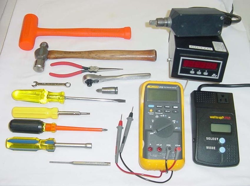
KITCHENAID
     Stand Mixer Service Manual Lit4177310-C                              2005 KITCHENAID

                                         Safety Guidelines
 This Service Manual is written for the Professional Service Technician who has familiarity with the
KitchenAid Stand Mixer. The following Safety Guidelines should be adhered to when servicing this product.

SERVICE ENVIRONMENT
•The workplace will be dry and sanitary at all times and all units should be inspected for cleanliness before
any work is started.
•Visually inspect the unit requiring service in a well luminated area.
•A mild, non-abrasive dishwashing soap solution and clean towel can be used to wash any unit requiring
attention.
•The hands of the service technician should be clean at all times during service procedure.

ELECTRICAL CONSIDERATIONS
•The workplace for the stand mixer will have properly grounded AC outlets that adhere to all Local
Electrical Codes that are applicable at the time of repair.
•The Stand Mixer Power Cord should always be inspected first before testing the mixer operation.
Do NOT run the mixer if the Power Cord is damaged -- replace it.
•All disassembly and assembly procedures discussed in this manual should be conducted with the unit
disconnected from the AC mains.
•Do NOT leave the unit unattended while running the mixer for speed range and bowl clearance checks.
Always unplug the unit immediately after concluding these tests.

Technician
•The Service Technician should wear Protective Eyewear at all times when conducting a repair on the Stand
Mixer.
•Loose fitting sweaters, shirts sleeves or bracelets should NOT be worn while servicing the Stand Mixer.

                                                   SAFETY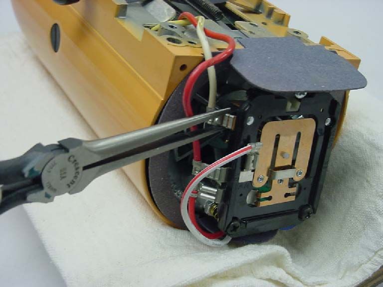
KITCHENAID
Stand Mixer Service Manual Lit4177310-C                             2005 KITCHENAID
   INDEX: Stand Mixer Repair Manual
      K45SS KSM75 KSM90 KSM103 KSM110 KSM150 KSM151
      K5SS KSM5 KSM50P KSMC50 KPM5 KPM50 KP50P

  SECTION               SUBJECT                                                PAGE
      -                 General Information                                    1
      1                 Disassembly of Gearcase and Planetary                  2
      2                 Disassembly of Motor and Control Unit                  6
      3                 Repairs to Motor and Control Unit                     11
      4                 Repairs to Gearcase and Planetary                      16
      5                 Repairs to Pedestal                                   21
      6                 Adjustment to Control Unit                             22
      7                Repairs to Bowl Lift Assembly                           26
      8                Troubleshooting the Bowl Lift Assembly                  30
  APPENDIX              SUBJECT
      A                Tools Required for Stand Mixer Service
      B                 Problem Solving Quick Reference Guide
      C                 Domestic Model Wiring Diagram
      D                International Model Wiring Diagram - RF Filter
      E                 International Model Wiring Diagram - Bowl Interlock RF Filter
      F                 Stand Mixer Serial Number Codes

                                   Introduction
   All KitchenAid Stand Mixers are well designed and carefully built. Normally they
  will give continual use year after year without service attention.
    Careful records have been maintained over a period of years to determine and
  correct, through improved design, any troubles that might possibly develop.
   An effort has been made in preparation of this manual to cover them all.
                                              INDEX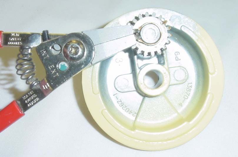
KITCHENAID
Stand Mixer Service Manual LIT4177310-C                                                        2005 KitchenAid
                                                                Heating
    GENERAL INFORMATION                                          Under normal conditions, the mixer will not show
Normal Performance                                              any tendency to heat because of the built-in
  The KitchenAid Stand Mixer is powered with a                  ventilating system in the motor.
universal motor which will operate on 50 or 60 hertz,            Under heavy loads with extended mixing time
alternating current only.                                       periods, the head may heat up to the point of being
  The Voltage of the power supply should be within 10           uncomfortable to touch.
volts either way of the voltage stamped on the mixer            Speed Control
trimband and nameplate.                                           The speed control of the mixer is attained through
  A mixer in good running condition will start turning          the use of a governor assembly mounted at the rear
slowly when the switch lever is moved from the “OFF”            of the control plate assembly.
position to the “STIR” position.                                  The electrical circuit is made and broken by the action
  As the switch lever is moved to successively higher            of the fly ball governor revolving against the control
positions, the speed of the beater increases until the #10      plate.
speed is reached.                                                 When the switch lever is moved to an ON position,
  At stir position, the planetary should turn at                 the position of the control plate with respect to the
approximately 60 RPM; at the #10 position all models            governor is changed by the action of the switch lever.
turn at approximately 255 RPM, with the exception of              Thus, when the control plate is set close to the
K45SS models built before May 6th, 2002 (WM19),                 governor, a relatively low speed of the motor causes the
which turn at approximately 280 RPM.                            governor to make or break the mixer’s electrical circuit
                                                                through the control plate.
 KITCHENAID STAND MIXER RPM
 SPEED           *K45SS       OTHER MODELS                        When the control plate is set farther away, a greater
 STIR              60 RPM            60 RPM                     motor speed is required before the governor starts
 #10              255 RPM            255 RPM                    breaking the circuit.
 Prior to May 6th, 2002,                                          The action of the governor is such that the speed of the
 #10              280 RPM                                       motor will remain constant for a given setting of the
*Note: All models have similar RPM, except K45SS                control plate within certain loads.
units built before May 6th, 2002, which run at 280 RPM            After certain loads have been exceeded, the speed of the
in the #10 position.                                            motor will drop to meet the torque requirements of the
  The mixer will run quietly in the lower speed range;          given load.
however, some noise can be expected on the higher speed           Speed is controlled by the governor and the control
settings due to hum of gears and the motor.                     plate in conjunction with the phase control.
 When the mixer is first turned to the stir position, there
                                                                         TRIAC RMS VOLTAGE
may be a slight clattering, irregular noise. This noise will
disappear as the lubrication in the gearcase warms up.              BOTH CONTACTS OPEN - 40 VOLTS
                                                                    ONE CONTACT OPEN - 80 VOLTS
 The switch lever should move freely with the “feel” of
definite positions for speed numbers stir, 2, 4, 6, 8 and 10.       BOTH CONTACTS CLOSED - FULL VOLTAGE
Speed numbers 3, 5, 7 and 9 do not have definite notches.           NOTE: The triac regulates the power the motor sees
                                                                      depending on control board contacts.
Power
 A mixer will have full power on all speed settings. To          A device called a triac is a part of the phase control
check for full power, carefully hold the planetary with         circuit.
one hand and move the switch lever on and off with the           This device determines the amount of power the motor
other hand.                                                     sees dependent upon the condition of the control board
 At the stir position, it should not be possible to stall the   contacts.
planetary except by a very great effort; nor should the          If both contacts are open, about 40 volts RMS is
planetary slow down noticeably when the retarding               applied to the motor and about 80 volts is applied when
pressure is applied.                                            either contact is closed and the other is open.

                                                           PAGE 1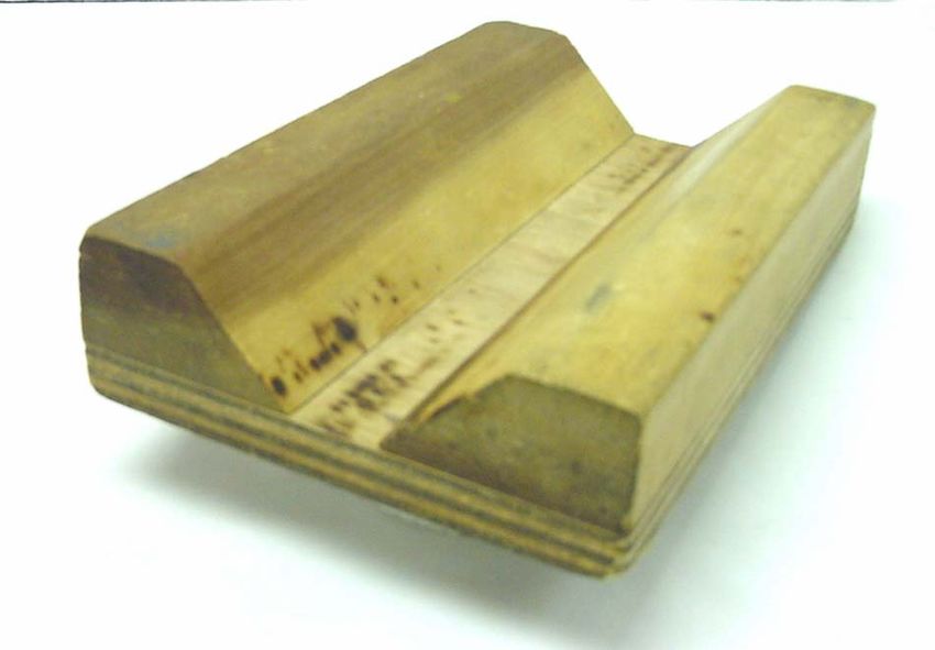
KITCHENAID
Stand Mixer Service Manual LIT4177310-C                                                 2005 KitchenAid
 When both contacts are closed, the triac is full                           SECTION 1
on; consequently, full power is applied to the             DISASSEMBLY OF THE GEARCASE AND
motor. In this way, the speed is controlled.                                  PLANETARY
 If the mixer motor begins to run too fast for a           A. All solid state KitchenAid mixers have the
particular speed setting, one or both contacts             same motor and control parts and the gears in the
open, which cuts back on the voltage the motor             gearcase are alike, with one exception: “K45SS
sees, thus slowing it up.                                  units built prior to May 6th, 2002.”
 If the motor operation becomes too slow, one or            Planetary parts are all the same, except that some
both contacts will close, applying the needed              early production K5SS had a lead weight.
voltage to the motor to sufficiently increase               Gearing and motor instructions are for both tilt
motor speed.                                               head and bowl lift machines and any differences
 This is always accomplished through the triac.            will be pointed out.
 The control plate contacts control the triac, and           BOWL LIFT - Models K5SS,KSM5,KSM50,
in turn, controls the amount of power supplied to           KSMC50,KPM5, KPM50, KP50. The bowl is
the motor.                                                 raised and lowered into position.
BEATER                                                       TILT HEAD - Models K45SS, KSM45, KSM75,
 The beater should fit freely on the beater shaft          KSM90, KSM103, KSM110, KSM150, KSM151,
located in the planetary.                                  KSM152. The mixer head is tilted up and down
 Power is transmitted from the motor to the                into position.
center-bevel gear assembly by means of the                  Bowl, column, base and bowl lift details are
worm gear.                                                 covered separately in section 7.
 The center-bevel gear assembly engages the                B. Before repairs are attempted on any KitchenAid
beater pinion, located in the planetary, to turn the       mixer, a wattmeter test should be made. To make
beater shaft.                                              the test, set the wattmeter to the proper voltage.
 The attachment hub bevel gear also meshes with             Next, plug the cord from the mixer into the
the center-bevel gear assembly to transmit power           wattmeter. Turn on the current and run the mixer.
when various attachments are being used.
LUBRICATION
 Under normal service conditions, the mixer will
not require lubrication for many years.
 The gear case is lubricated with an ample supply
of Benalene 930-2 grease (6 fluid ounces), which
lubricates all the gears and shafts.

 GEARCASE LUBRICATION
  All KitchenAid Stand Mixer Gearcases are
 lubricated with 6 Fluid Ounces of:                         KitchenAid stand mixer shown with a digital wattmeter
 BENALENE 930-2 GREASE (OR EQUIVALENT)
                                                            If the wattmeter shows up to 135 watts, going from
  NOTE: Gearcases lubricated with this grease
                                                           stir to #10 speed, the mixer is in good condition.
         will not require lubrication for years.
                                                             If the wattmeter reading is 175 to 400 watts, there
                                                           is a problem.
 The motor bearing and the beater shaft bearing
                                                             High wattage mixer readings indicate either
are oil impregnated.
                                                           electrical or mechanical problems.
 The rear motor bearing has a felt washer which
                                                             Check first for bearing/gear drag, then for
has been presoaked in oil.
                                                           motor/brush problems.
 The front motor bearing in the mixer housing is
                                                           CAUTION: Always remove power cord from
a ball bearing.
                                                           electrical outlet before servicing any part of the
                                                           mixer.
                                                       PAGE 2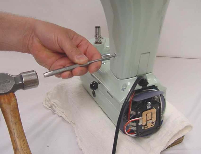
KITCHENAID
Stand Mixer Service Manual LIT4177310-C                                               2005 KitchenAid
C. Note: remove the bowl and any attachments
     before disassembly of unit.
 Remove the #6-32x3/8” (tapered head) screw
from the end cover (Fig. 1).

                     FIG # 1
                                                         Fig. 3 Loosen the hinge pin setscrew to remove the
                                                         pedestal from the bottomcover.
                                                         Using a drift punch and hammer, drive out the
                                                        hinge pin (Fig. 4) and lift the pedestal off the
Fig. 1 The end cover is removed by removing the         gearcase-bottom cover.
tapered head endcover screw.

  Remove the two #6-32x3/16” screws that hold the
trimband to the gearcase-motor housing (Fig. 2).
With the screws removed, take the trimband off and
set aside.

                                                        Fig. 4 A drift punch and hammer is used to drive out the
                                                        hinge pin.

                                                        E. To remove the planetary, first remove the drip
                                                        ring . Use a screwdriver on the upper edge of the
Fig. 2 The trimband can be removed after removing the   drip ring and gently tap the screwdriver to remove
trimband screws.                                        the drip ring (Fig. 5).
D. To save the paint, lay the unit in a padded cradle
or on a cloth pad.
 To remove the pedestal from the gearcase-bottom
cover, turn the unit upside down in a padded cradle.
 Loosen the set screw with a screwdriver (Fig. 3)
                                                    PAGE 3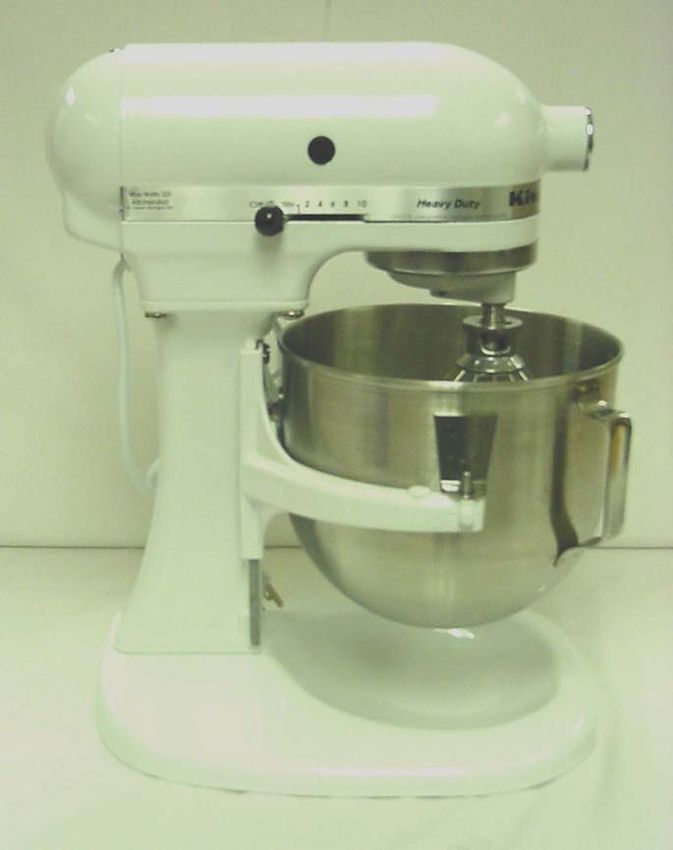
KITCHENAID
Stand Mixer Service Manual LIT4177310-C                                                             2005 KitchenAid
                                                                  F. Remove the power cord from the bottom cover
                                                                  by sliding the molded strain relief out of the slot in
                                                                  the bottom cover (Fig. 8).

Fig. 5 The Drip Cup fits tightly and must be started off by
      tapping it.
 With a 5/32” drift punch, remove the groove pin
that holds the planetary to the vertical center shaft
(Fig. 6).
                                                                   Fig. 8 Pull back on the molded strain relief to remove
                                                                   the power cord from the slot in the bottom cover.

                                                                   To remove the power cord with the Heyco strain
                                                                  relief used on older models, use a pair of pliers to
                                                                  squeeze the strain relief while pulling up (Fig. 9).
                                                                  Reverse this procedure to reinstall it.

Fig. 6 Removal of the groove pin that holds the
planetary to the vertical center shaft
  With the pin out, the planetary can be removed
from the center shaft. Using two (2) screwdrivers,
pry the planetary up and off the shaft (Fig. 7).

                                                                       Fig. 9 Removal of Heyco strain relief using pliers.

                                                                  G. To remove the bottom cover from the gearcase-
                                                                  motor housing, unscrew the five (5) #10-24 special
                                                                  screws (Fig. 10). These screws hold the internal
                                                                  gear into the bottom cover.
                                                                   Next remove the four (4) filister head screws from
                                                                  the bottom cover (Fig. 11).
Fig. 7 Use two screwdrivers to pry the planetary off the
shaft.
                                                              Page 4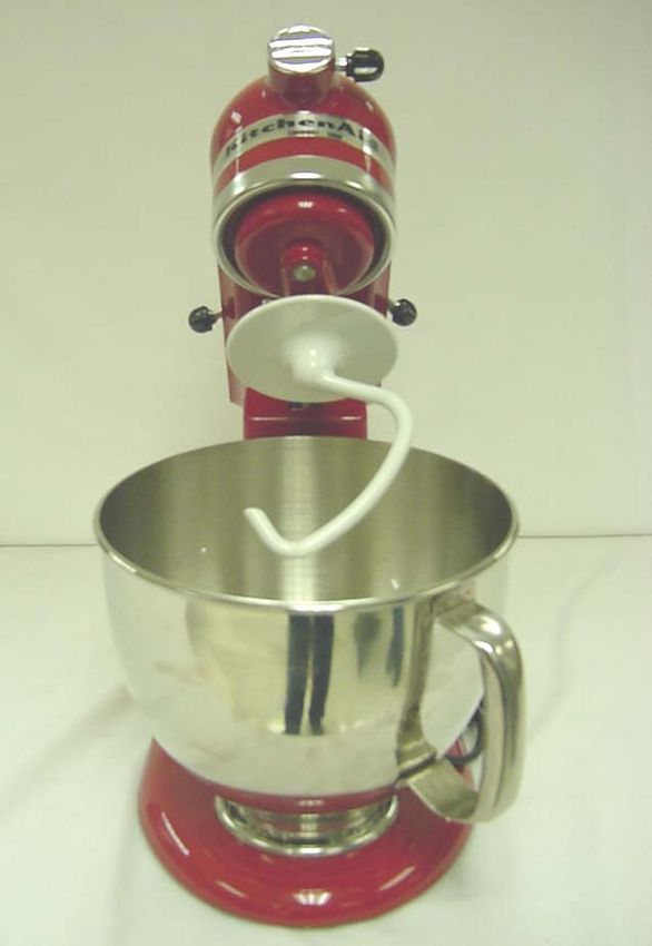
KITCHENAID
Stand Mixer Service Manual LIT4177310-C                                                     2005 KitchenAid

Fig. 10 Removal of the 5 special screws holding the           Fig. 12 While lifting up on the center shaft, use a screw
internal gear in the bottom cover.                                  driver to gently pry the bottom cover from the
                                                                    housing.
                                                             H. Remove the attachment hub bevel gear from
                                                             the gearcase-motor housing.
                                                              This gear is removed by simply pulling it out of
                                                             the attachment hub (Fig. 13). The gear will clear
                                                             the worm of the motor’s armature shaft and
                                                             should be easy to remove.
                                                             Note: For clarity, the pictures in this manual have
                                                             no grease shown in the gearcase. Normally the
                                                             gearcase has 6 oz. of grease surrounding the gears.

 Fig. 11 The bottom cover is removed after removing the
      four #10-24 filister head screws.
 To remove the bottom cover from the gearcase-
motor housing, insert a drift punch through the hole
in the center shaft and lift, while using a screwdriver
to break the bottom cover loose.
 Use the slots in the side of the gearcase to do
this (Fig. 12).
 Do NOT pry in the area of the transmission gasket,          Fig. 13 The attachment hub bevel gear being removed
as this may prevent the gasket from sealing properly         from the mixer attachment hub bearing.
upon reassembly.                                             I. Clean out the gearcase and remove as much of
 The transmission gears will come out with the               the grease as possible.
bottom cover. Be careful not to allow any grease to           The gearcase may be thoroughly cleaned when
fall into the motor area of the housing.                     the motor has been removed.

                                                          Page 5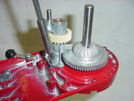
KITCHENAID
Stand Mixer Service Manual LIT4177310-C                                              2005 KitchenAid
                    SECTION 2                             Remove the end seal and disconnect the phase
 DISASSEMBLY OF STAND MIXER MOTOR                       control flag terminals from the control board
               AND CONTROL UNIT                          (Fig. 16).
    Note: All service operations discussed
   here should be performed with the mixer
   disconnected from the A. C. mains.

A. Start the disassembly of the control unit by
removing the cord flag terminals from the control
board and the ground wire from the bearing bracket
(Fig. 14).

                                                          Fig. 16 After removing the end seal, remove the
                                                          phase control flag terminals.

                                                         Unhook the control board spring at the bottom of
                                                        the control board (Fig. 17).

  Fig. 14 Removal of the cord flag terminals and
  cord ground wire.
 Remove the motor stator flag terminals from the
control board ( Fig. 15).

                                                              Fig. 17 Unhook the control board spring.

                                                         Unlock the two lock nuts on the control board and
                                                        unscrew the two adjusting screws.
                                                         The mixer control board can now be removed and
   Fig. 15 The removal of the motor stator flag
                                                        set aside for later evaluation (Fig. 18 ).
   terminals from the control board.

                                                     Page 6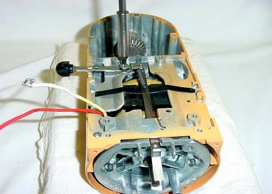
KITCHENAID
Stand Mixer Service Manual LIT4177310-C                                                  2005 KitchenAid

    Fig. 18 Mixer housing with end seal and                     Fig. 20 Phase control or (triac) shown
    control board removed.                                      removed in lower center.
B. The phase control can now be disassembled from
the bearing bracket, if necessary, by unscrewing the
#4-40 x 1/4” pan head screw (Figs. 19 & 20).

                                                            Fig. 21 Needle nose plier used to pry governor off
                                                            the motor shaft.

    Fig. 19 Removal of the phase control (Triac)
    from the bearing bracket.

C. With a pair of needle nose pliers, carefully pry
off the governor assembly. (Fig. 21) Do NOT
bend.
  Remove the governor drive pin and lay it aside so
it will not be lost (Fig. 22).
                                                            Fig. 22 Governor shown removed from the shaft
                                                            of the motor.
                                                       Page 7
KITCHENAID
Stand Mixer Service Manual LIT4177310-C 2005 KitchenAid
D. To remove the speed control link and cam
assembly, take out the pivot screw and tension
washer (Fig. 24).
Flat Spring
Fig. 25 Removing the speed control spring, flat spring and
the speed control link assembly.
E. Unscrew and remove the two #10-24 nuts
(Fig. 26).
Fig. 24 The pivot screw and tension washer are removed
with a phillips screwdriver.
Before removing the speed control link and cam
assembly, remove the control board spring from the
link.
The flat spring is removed as you remove the speed
control link assembly.
The speed control link and cam assembly can be Fig. 26 Two 10-24 nuts are removed from the
removed by pulling it out of the gearcase-motor bearing bracket.
housing (Fig. 25).
Remove the bearing bracket (Fig. 27).
Now remove the motor stud sleeve from the stator
stud (Fig. 28).
Page 8KITCHENAID
Stand Mixer Service Manual LIT4177310-C 2005 KitchenAid
Fig. 27 Bearing bracket being removed after two #10-24 Fig. 29 the brush holder caps are loosened to access
nuts have been removed. brushes for removal. Make sure to mark orientation.
G. The armature can now be removed.
With the attachment hub bevel gear removed,
insert a drift punch through the attachment hub
opening and gently tap the armature back through
the stator using a block of wood to protect the
shaft (Fig. 30).
Fig. 28 The motor stud sleeve is shown being removed after
bearing bracket removal.
F. Unscrew the two brush holder screw caps and
remove the brushes and springs (Fig. 29).
Viewing from the rear, mark the brushes right and
left, and also the top of the brush, just as it was
removed from the motor. Fig. 30 A block of wood is used to protect the motor
shaft when removing the armature.
Remove the worm end bearing washer and the
fan end spacer washer.
Page 9KITCHENAID
Stand Mixer Service Manual LIT4177310-C 2005 KitchenAid
H. Pull the two wires from the rear of the stator I. To remove the brush holder , it will be
through the slot in the gearcase-motor housing so necessary to remove the other stator stud.
they are inside the gearcase-motor housing and Under the stator studs are #10-24x1/4 cup point
sticking out the back (Fig. 31). screws. To remove the set screws, use a 3/32”
Allen wrench; older models may use a flat
screwdriver (Fig. 33).
Stator Wires
Fig. 31 Wire orientation inside the gearcase-motor housing
Using long pliers, pull the brush slips from the
stator out of the brush holders. Note orientation of
stator clip in brush holder.
Remove the two #10-24 nuts from the stator studs
and carefully set aside for use during reassembly.
Unscrew one stator stud and pull out the stator
Fig. 33 Removing the brush holder set screws with a
(Fig. 32). allen wrench.
Unscrew the set screws a few turns and (from
inside the housing) push the brush holder out by
hand. Note the orientation of the brush insert
inside the brush holder.
Fig. 32 The stator is shown being removed from the motor
housing.
To pull the stator out, reach into the motor housing
and grasp the stator and pull it out. Caution: Do
not nick or damage the copper coil wires on
the motor. Page 10KITCHENAID
Stand Mixer Service Manual LIT4177310-C 2005 KitchenAid
C. Test the stator with an ohmmeter (Fig. 35).
SECTION 3 Set the ohmmeter on the 1X scale and be sure it is
REPAIRS TO MOTOR AND CONTROL UNIT set at zero ohms when shorting the test leads.
A. Clean the brush holder with solvent and
wipe them dry with a clean dry cloth.
Install the brush holder into the gearcase-
motor housing so that the rim on the holder seats
against the bore step in the motor housing.
B. Clean the brush holder inserts with solvent and
wipe them dry with a clean dry cloth. Install the
inserts into the brush holder.
They must be oriented, viewing the motor housing
from the rear, as shown below in (Fig. 34).
Fig. 35 Test the two stator coils with an ohmmeter set on
low scale.
In upper coil, connect one ohmmeter lead to the red
wire and the other to the black wire of the coil.
If the ohmmeter shows a low resistance reading, the
coil is good. Check the other coil in the same way.
If the needle on the ohmmeter deflects to zero or
there is no deflection, the coil is bad and the stator
must be replaced.
D. Assemble the two stator studs and tighten them
by using long nose pliers.
Be sure the nose of the pliers is placed on the stator
stud in the area that the stator seats so the threads
will not be deformed.
Start the stator on the two stator studs and into the
Fig. 34 The orientation of the brush holder inserts viewing ribs of the motor housing (Fig. 36).
from the rear of the motor housing.
Lock the brush holder with inset in place
with the #10-24x1/4” cup point setscrews.
EARLY PRODUCTION SOLID STATE
STAND MIXERS
The early production solid state stand mixers
utilized a square brush and brush holder. Square
brushes are no longer available.
Brushes with chamfered edges will fit into square
brush holders.
Fig. 36 Positioning the stator on the two stator studs and
into the ribs of the motor housing.
Page 11KITCHENAID
Stand Mixer Service Manual LIT4177310-C 2005 KitchenAid
The two long leads from the stator must be on the
same side as the slot in the motor housing. Insert the
stator brush clips between the brush holder housing Bearing Washer
and brush insert.
A slot is provided in the brush holder housing for Spacing Washer
this brush clip. Insure that the brush clips are pushed
in all the way so the brush and commutator on the
armature will clear them when assembled.
E. Push the stator back as far as it will go, then
place the star washers and #10-24 nuts on each
stator stud.
Tighten both nuts.
Put the long leads from the stator through the slot
in the bottom of the motor housing (Fig. 37).
Stator Wires
Fig. 38 Check the blades of the armature ventilating fan
and straighten if bent.
Routing Of
White Wire
Fig. 37 Route the two stator wires through the slot in the
motor housing.
Place the stator stud sleeve over the stator stud and
route the white wire from the stator between the stud
sleeve and the motor housing. Fig. 39 Locating the armature into the gearcase-motor
housing.
F. Check the armature on a growler or take the If necessary, tap the end of the armature shaft
armature to a electric motor repair shop and let them with a non-metallic mallet to seat the armature
test it. bearing into the gearcase-motor housing.
If it is not in good condition, replace it with a new
one. H. Check the bearing in the bearing bracket.
G. Check the ventilating fan. Straighten the blades To replace the bearing, remove the retaining
if they are bent (Fig. 38). clip (Fig. 40).
If the armature is replaced, move the washers from Take out the felt washer and the old bearing.
the old armature to the corresponding end of the new Place the new bearing in cavity.
armature. Soak the felt washer with oil and place in cavity.
Add one drop of Locktite to the outer race of the Place the retainer on the bearing so that the
ball bearing and install the armature in the tongue fits into the square notch and push the
motor housing (Fig. 39). retainer clip in place.
Page 12KITCHENAID
Stand Mixer Service Manual LIT4177310-C 2005 KitchenAid
On older models, to replace the bearing, remove the J. The armature should always be checked for end
three #4-40x1/2 pan head screws and lift off the play. Armature should turn freely with minimal
bearing retainer. end play.
Take out the old bearing and felt washer. On older models - after the thrust bearing
Place new bearing in cavity with the square notch assembly has been seated properly and proper
toward the top of the bracket. amount of spacing washers placed at the rear, there
Soak the felt washer in bearing cap with oil. should only be a perceptible amount of end play to
Place the retainer on the bearing and screw in place assure free operation of the armature.
with the three #4-40x1/2” screws. If there is too much end play, add another thin
washer.
To do this, remove the bearing bracket and add
the washer to the armature shaft, then reassemble
the bearing bracket into the gear case-motor
. housing.
K. If the old brushes are more than 5/16” long,
assemble them in the brush holders.
From the back of the unit, put the brush marked
“right” in the right side of brush holder. Be sure the
Tongue side marked “up” is at the top.
Push the brush in and lock it in place with a brush
holder screw cap (Fig. 42).
Square Notch Put left hand brush in the mixer in the same way.
Fig. 40 Bearing bracket assembled & unassembled
I. Install the bearing bracket. Start bracket onto the
two stator studs.
Push the bracket back until the stator studs are
through the bracket and it seats into the ribs of the
gear case.
Start the two nuts on the stator studs and turn them
until the bearing bracket is seated (Fig. 41).
Brush holder screw cap assembly
Fig. 42 Placing one of the brushes into the mixer brush
holder.
L. Place the speed control link and cam assembly
through the slot in the bearing bracket with the cam
portion of the speed control link and cam assembly
toward the top of the gearcase-motor housing.
Place the flat spring in position and slide the
mixer speed link and cam assembly over the flat
spring; attach the speed control spring on the speed
Fig. 41 Tighten the two nuts on the stator studs to seat the control link and cam assembly (Fig. 43).
bearing bracket.
Page 13KITCHENAID
Stand Mixer Service Manual LIT4177310-C 2005 KitchenAid
Flat Spring
Speed Control Spring
Fig. 43 Slide the speed control link over the flat spring and
attach the speed control spring to the link.
Place the stud on the speed lever through the hole
in the speed control link.
Fig. 45 The governor shown before being placed on the
Place the tension washer on the pivot screw and
motor shaft.
screw it into the gearcase-motor housing until tight
(Fig. 44).
Fig. 44 Securing the pivot screw to the gearcase after
placing the tension washer.
M. If the spring in the governor is rusty, replace
the governor assembly.
Place the governor drive pin in the armature shaft.
With drive pin at top of the shaft, place the Fig. 47 Using a 3/8” nut driver to seat the governor. Tap
gently. Never drive directly against governor ball.
governor on the shaft with the keyway up (Fig.45).
Push the governor onto the shaft as far as it will
go.
NOTE: Never attempt to take the governor apart.
The purpose of this picture is to show where
governor seats on drive pin (Fig. 46).
Page 14KITCHENAID
Stand Mixer Service Manual LIT4177310-C 2005 KitchenAid
N. If the phase control was removed or has been Turn in the screws until 3/8” of the screw
replaced, make sure the heat sink on the triac unit remains.
has sufficient amount of thermal conductive Have both screws turned in evenly so the opposite
compound applied to that surface before assembly. end of the control plate rests squarely on the
Place the #4-40x1/4” pan head screw through the extensions of the bearing bracket.
hole in the triac and screw it into the bearing bracket With long nose pliers, hook the control plate spring
(Fig. 48) until it is tight (4 - 5 in. lbs.). into the hole on the bottom part of the control plate
(Fig. 50).
Fig. 48 The triac is shown being secured to the bearing
bracket. Fig. 50 The control plate spring being grasped with pliers
CAUTION: Do not attach the phase control and positioning the hook into the hole at the bottom.
excessively tight, as this pressure could deform the
heat sink, resulting in damage to the control. Place the end seal onto the mixer.
Connect the two flag terminals from the stator and
O. Place the control plate on the bearing bracket the four flag terminals from the phase control to the
with the adjusting screws at the top (Fig. 49). control plate.
Refer to the wiring diagram for proper terminal
connections.
Be certain flag terminal connections to control
plate are tight.
If necessary, crimp the terminals with a needle
nose pliers.
Note: Leave the control unit. It is now ready for
timing, but a better job can be done when mixer is
completely reassembled.
Fig. 49 Placing the control board on the bearing bracket.
Page 15KITCHENAID
Stand Mixer Service Manual LIT4177310-C 2005 KitchenAid
SECTION 4
REPAIRS TO GEARCASE AND PLANETARY
NOTE: Grease is not shown in these pictures.
A. Examine the bearings in the attachment hub area
and top of the gearcase.
These bearings are cast into the gearcase-motor
housing.
If they are worn badly, the entire housing must be
replaced.
However, shafts turn slowly in these bearings and
the bearings have a long life.
B. Examine the attachment hub bevel gear.
If it shows wear in the teeth, it should be replaced.
If the gear is replaced, coat the shaft of the bevel
gear with a light grease. Fig. 52 Worm gear bracket bearing and pin assembly.
Push it into the attachment hub bearing from the
inside of the gearcase (Fig. 51). It does not have a D. Remove the center bevel gear and vertical center
washer, so push it in as far as it will go. shaft.
Push the vertical center shaft upward, exposing the
pin (Fig. 53), and remove the pin.
Fig. 51 The attachment hub bevel gear being pushed into
the attachment hub bearing from inside the gearcase.
Fig. 53 Remove pin after pushing vertical center shaft up.
C. With a phillips head screwdriver, remove the
three #10-24x7/16” phillips filister head screws and Pull out the vertical center shaft with your fingers
lock washer assemblies and lift up on the worm and remove the shaft from the the bottom of the gear
gear bracket bearing and pin assembly to remove case bottom cover (Fig. 54).
(Fig. 52). Check the shaft for bearing wear.
Dark gray or indented surfaces indicate shaft
should be replaced.
Lift gears from case for inspection (Fig. 55).
Page 16KITCHENAID
Stand Mixer Service Manual LIT4177310-C 2005 KitchenAid
Push shaft upward and insert the pin (Fig. 53).
Center pin in shaft and lower shaft into gear
assembly.
Turn shaft until pin seats in gears, and gears and
shaft turn together. Wipe all excess lubricant from
bottom of vertical shaft on “O” ring.
H. Check the worm gear and pinion gear (Fig.56).
Worm Gear
Fig. 54 Removal of vertical shaft from bottom cover.
Pinion gear and shaft
Shim washer Fig. 56 Check worm gear and pinion before reassemble.
To replace these gears, drive out the groove pin
(Fig. 57).
Fig. 55 Bevel center gear being lifted for inspection.
E. Check the lower center bearing for wear.
This is an oilless bearing and should be in good
condition. Drive pin
If it is worn, the gearcase bottom cover will have
to be replaced, since the bearing is an integral part.
Fig. 57 The drive pin must be removed to change the
F. If the attachment hub bevel gear was replaced, gears.
then the bevel center gear on the bottom cover Make a note of the positions of fiber washers.
must also be replaced. They will be installed the same way with the new
gears. From the top of the worm gear bracket, drive
G. Place the same washer on lower center bearing. out the pinion shaft.
Place the gear assembly on top of the center
bearing. Insert the end of the vertical center shaft NOTE: The pinion on pre May 6th, 2002,
opposite the “O” ring into the bottom cover K45SS models, have 11 teeth. On all other units
(Fig. 54). the pinion has 10 teeth.
Page 17KITCHENAID
Stand Mixer Service Manual LIT4177310-C 2005 KitchenAid
I. Start a new pinion gear and shaft from the bottom K. Check the latch, link and lever assembly.
of the bracket. Before the shaft emerges from the There should be no wear or trouble with this
lower bearing, place a washer on the bearing and assembly (Fig. 58).
start the shaft into the washer. L. Use 6 oz. of Benalene 930-2 lubricant and
Place a new worm gear next and push the shaft lubricate around the gears when filling the gear
up into it. Place the second washer on top of the case.
worm gear and push the pinion shaft up into the upper This product is available through your nearest
bearing. authorized distributor.
Line up the drive pin holes in the shaft and worm Try to keep the bearing in the top of the gear
gear and drive in the groove pin. case open. It will help when assembling the bottom
J. Place the worm gear assembly and bearing cover and gearcase motor housing together.
bracket on the bottom cover so that the two dowels M. Clean the gasket surface of the gear case.
will fit into the base of the bearing bracket (Fig. 58). Place a new gasket on the gearcase, over the
dowel pin, and press it down so it will stay in
Latch Link Lever position.
N. Check the cord and plug.
If it is drying and cracking - Replace it.
O. Lock the latch lever and hold the bottom cover
in position over the gearcase-motor housing and
start joining them together (Fig. 60).
Dowel pin
Fig. 58 The two dowels must fit into the base of the worm
gear bracket.
Place the three lock washer screw assemblies in
the holes and screw them into the bottom cover
(Fig. 59). Be sure screws are tight. (18 - 23 in/lbs.)
Lock washer screw
assembly
Fig. 60 Initial mating of bottom cover to gearcase - motor
housing.
Start the shaft into the upper bearing and slowly
push the parts together. Insert a punch into the
center shaft, turning back and forth, while pressing
down on the bottom cover, to align the gears.
CAUTION: Under no circumstances should you
force the gearcase and bottom cover together.
If the gears are properly aligned, these two parts
will assemble with little or no force required.
Fig. 59 Secure the three lock washer screw assemblies into
the bottom cover.
Page 18KITCHENAID
Stand Mixer Service Manual LIT4177310-C 2005 KitchenAid
P. If necessary to replace the internal gear, pry it
from the bottom cover (Fig. 61).
Fig. 63 Secure the four fillister head screws.
The bearing is an integral part of the planetary.
Hold the agitator shaft firmly and remove the
pinion retaining clip (Fig. 64).
Fig. 61 Internal gear can be pried from the bottom cover and
replaced if necessary.
When installing new gear, start with beveled side
down; align notches with holes in gear case and tap
evenly into place using a non-metallic mallet.
Insert and tighten the five special screws evenly
(Fig. 62) to 18 - 20 in. lbs. torque.
4
2
1 Fig. 64 Hold the agitator shaft and remove the retaining
clip.
Lift off the pinion. Take out the pin and remove
3 the washer (Fig. 65). Pull the agitator shaft out.
5
Fig. 62 Tighten the five special screws evenly to 18-20 in.
lbs.. torque using the sequence shown.
Insert the four #10-24x1” fillister head screws into
the bottom cover making sure they are tight (Fig. 63)
(18 - 20in/lbs.).
Q. Place a small amount of Benalene 930-2
lubricant on the teeth of the internal gear.
R. Check the condition of the planetary. If there is
any play in the agitator shaft and the bearing (not Fig. 65 Lift the pinion off and take out the pin and
shown), replace the planetary and the shaft. remove the washer; then pull out the shaft.
Page 19KITCHENAID
Stand Mixer Service Manual LIT4177310-C 2005 KitchenAid
S. The agitator shaft is complete as an assembly.
Lubricate the shaft and push it up into the bearing as
far as it will go. Place the washer(s) on the shaft.
Insert the pin through the shaft. Set the pinion gear on
the shaft so that the notches in the pinion align with
the pin in the shaft. Install the retaining clip in the
groove on the shaft (Fig. 64).
Fig. 68 Carefully drive the groove pin into the shaft of the
planetary.
V. Place the drip cup on the bottom cover. Tap it
down into place using a non-metallic hammer.
W. Check the beater height adjusting screw
(Fig. 69).
Fig. 66 The planetary components are shown disassembled. This screw is slotted and has a nylon insert.
As it is screwed in, threads are cut in the nylon
T. Place the washer(s) on the vertical shaft.
and hold the screw tight.
Be sure the planetary pinion and the internal gear
Replace this adjusting screw if it is loose in the
have a light coat of grease (Benalene 930-2) on them.
threads.
Place the planetary on the shaft and push it down.
Line up the holes in the planetary and shaft. It may
be necessary to use an awl or pointed punch to align
the holes (Fig. 67).
Fig. 69 The adjusting screw has a nylon insert and
should not be loose in the threads.
Fig. 67 A pointed punch can be used to align the holes of the
shaft with the planetary.
U. Drive the groove pin into the shaft (Fig. 68).
There should be a very small amount of end play.
Page 20KITCHENAID
Stand Mixer Service Manual LIT4177310-C 2005 KitchenAid
. SECTION 5 C. If the bowl screw cap has worn out, be sure to
replace it.
REPAIRS TO TILT HEAD PEDESTALS To remove the old cap, take out the three #10-
24x1/2” flat head screws and lift out the old cap.
A. If pedestal is removed, check the hinge pin. If it is Put the new cap in place and screw it down tight
galled from failure to loosen the set screw, replace with the three screws (Fig. 72)(24- 32 in/lbs.).
it (Fig. 70).
Hinge pin
set screw
Fig. 72 The new cap is secured to the pedestal with three
screws.
Fig. 70 The set screw in the bottom of the pedestal should
clear the hinge pin. D. While in the cradle, place the pedestal on the
Loosen the set screw so that it will clear the hinge bottom cover.
pin. Place the new hinge pin in the pedestal, but do Line up the holes for the hinge pin and tap it in so
not drive it in. that an equal amount of the pin extends on each
side of the pedestal (Fig. 73).
B. Check the rubber feet. If they are worn or softened
from grease, replace them.
Twist the old feet out (Fig. 71). Clean the holes
with solvent and dry them with a clean cloth.
Fig. 73 Use a rubber or rawhide mallet to tap the hinge
pin into the pedestal.
E. Using a flat blade screwdriver, tighten the hinge
Fig. 71 The pedestal feet should be replaced on older mixers. pin set screw up inside of the pedestal (Fig. 70).
Moisten the part of the foot that will go into the hole
and twist the new foot in or tap with a mallet.
Be sure all feet are penetrating the pedestal an equal
distance to maintain a level foundation.
Page 21KITCHENAID
Stand Mixer Service Manual LIT4177310-C 2005 KitchenAid
F. On international export models shown (Fig. 74), SECTION 6
a plastic head lock foot has been riveted to the ADJUSTING THE CONTROL UNIT
pedestal to permit the locking of the motor housing in
the “inclined” position. NOTE: When replacing a control plate, a cloth,
The lock lever on these models is spring loaded and (Fig. 76), hooked over the control plate spring,
the locking action is obtained by removing tension will keep the spring accessible, not allowing it to
from the lever after the motor housing has been put in “snap” between the upper and lower gear case and
the “inclined” position (Fig. 74). become “lost.”
Plastic headlock Control plate spring
Fig. 74 A plastic headlock has been riveted to the pedestal Fig. 76 Hold the control plate spring with a cloth to retain
access for reassembly.
of international export models. An international model is
shown locked in the “inclined” position. This is obtained by A. After installing new parts in the control unit,
the action of the spring loaded lock lever used on these the control plate must be adjusted so that all speeds
models. will be the same as they were when the mixer was
new.
The small circuit board shown (Fig. 75) is an RF
B. Make sure that all of the wire leads are properly
filter used on international models that is held to the
connected and that they are locked in position
bottom cover with a single round head screw.
properly.
Plug the cord into a receptacle having the proper
voltage.
C. To adjust the speeds, move the switch lever to
stir.
This may or may not start the motor.
If motor did not start, turn out the two adjusting
screws evenly and stop when planetary turns about
60 revolutions per minute.
To test the speed, hold a finger of the right hand at
the planetary.
Let the beater shaft hit the finger (Fig. 77).
Count the number of times the finger is touched in
15 seconds.
Adjust the two screws until the shaft touches the
finger about 15 times in 15 seconds.
D. When proper speed has been set, lock the two
lock nuts using a 11/32” wrench (Fig. 78) and
Fig. 75 International model bottom cover with R F filter and check the speed again.
spring loaded lock lever.
Page 22KITCHENAID
Stand Mixer Service Manual LIT4177310-C 2005 KitchenAid
Fig. 77 Carefully let the planetary touch your finger to test Fig. 79 Adjusting screw at the bottom of the control plate
speeds. for speed # 6.
F. Try all mixer speeds from stir to #10.
If stir and #6 are properly adjusted, the other
speeds should automatically be correct.
If there is a definite change in speed between #8
and #10, the control unit is correctly adjusted.
G. A digital speed device (Fig. 80) is available to
adjust the planetary speed settings on all
KitchenAid mixers.
Insert this end into
the attachment hub
Fig. 78 Once proper speed setting has been obtained, lock
the two 11/32” lock nuts.
If a small correction must be made, make it without
loosening the lock nuts.
Test speeds as before, and, when correct, it will not
be necessary to disturb the lock nuts.
E. Move the switch lever to speed #6. At this setting,
the planetary must turn at 180 revolutions per minute.
Fig. 80 Electronic speed measuring device, with
Check the speed as was done for stir speed. numerical display for setting speeds on KitchenAid
The planetary should touch your finger 45 times in mixers .
15 seconds. To use this device, the main control box needs to
If the planetary touches the finger less than that, turn be plugged into a 120 volt power source.
the adjusting screw at the bottom of the control plate Insert the tapered metal end of the speed sensing
(Fig.79). unit into the attachment hub of the mixer. The
Check the revolutions again and keep adjusting the tapered hub is machined the same as all mixer
screw at the bottom until the right speed is reached. attachments. Secure it in place by tightening the
There is no locking of this screw. thumb screw.
Page 23KITCHENAID
Stand Mixer Service Manual LIT4177310-C 2005 KitchenAid
The control plate is spaced 3/8” from the
mounting bracket for the proper speed setting
“Starting Point.”
Plug the mixer into a watt meter set at the proper
voltage.
Turn the mixer to “Stir Speed.” The mixer may or
may not start. If not, turn the two mounting screws
out evenly until mixer starts. Adjust both screws
evenly until a speed setting of 40 (40 - 64) is
attained.
Turn mixer to speed #6. The single screw at the
bottom of the control plate is used to control this
speed; adjust to attain a speed of 150 (141 - 170 ).
Turn speed control to speed #8, pause, then turn
to speed #10. There should be a noticed speed Fig. 81. Replace the trim band on the gearcase after
speeds have been set.
increase between #8 and #10 speeds. If not, back
speed #6 down slightly until there is at least a
minor speed change between #8 and #10.
The #10 speed should be at least 185 (185 - 250).
When proper speeds have been set, lock the two
lock nuts on the upper mounting screws using an
11/32” wrench.
Be careful not to move the mounting screws in or
out during the locking process.
Recheck speeds after locking the nuts, and if a
fine adjustment is needed, it can be done without
loosening the locking nuts.
G. Place the trimband (Fig. 81) on the gearcase -
motor housing, and with the two # 6-32 x 3/16” Fig. 82. The end cover is secured to the mixer with a
screws, fasten it to the housing. tapered head screw.
Tuck in all the wire leads- insure no wires are
pinched - and place the end cover
on the end of the motor housing and secure it with
the # 6-32 x 3/8” oval head screw (Fig. 82).
H. With the end cover on the machine, test the
speeds again to make sure no change took place in
the control plate.
With mixer working correctly, place the bowl on
the bowl screw cap.
Place the flat beater on the agitator shaft.
There should be approximately 1/16” clearance
between the bowl and beater.
If the beater is too close to the bowl, turn the
beater height adjusting screw “out” or “in” if it is
too far away (Fig. 83).
The mixer is now ready for operation. Fig. 83 The beater height adjustment screw used to set
the 1/16” clearance between the bowl and beater.
Page 24KITCHENAID
Stand Mixer Service Manual LIT4177310-C 2005 KitchenAid
SECTION 7 .
REPAIRS TO BOWL LIFT ASSEMBLIES ON
BOWL LIFT MODELS
A. The bowl lift models of KitchenAid mixers have
a different type of bowl and are different in size.
On the tilt head models, the bowl is held stationary
by mechanical means at the bottom of the mixer
pedestal; whereas, on bowl lift models, the bowl
support slides up and down gibs on the column.
B. Should the mixer be tipped over or knocked off
the table or counter, the unit’s bowl support
assembly may be broken. To repair it, it will be
necessary to replace the bowl support. Fig. 85 Lift the column and bowl support assembly off of
the bottom cover.
C. To replace the bowl support, remove the four
5/16”-18 x 3/4” round Phillips head screws (Fig. 84)
and lift the column and base assembly off the bottom
cover (Fig. 85). KSMC50 models use 5/16”- 18 x3/4”
hex head screws.
Fig. 86 Remove the four round head screws from the base
to remove the bowl lift assembly.
BEATER HEIGHT
ADJUSTING SCREW
Fig. 84 Four round Phillips head screws must be removed to
replace the bowl support assembly.
D. With the bowl lift assembly on the bench, lay it
on its back and then remove the four 5/16”-18 x 3/4”
round head screws (Fig.# 86) from the base and set
the base aside.
E. Remove the two #10-24x1/2” flat head screws
from the bowl support (Fig. 87) and slide the bowl
support down and off the column (Fig. 88).
F. Examine the bowl lift arm. This part is held on the
bowl lift handle with a tapered pin.
If the arm is cracked at the pin hole, replace it. Fig. 87 Two flat head screws hold the bowl support to the
If there is any fault with the column, replace it at bowl lift assembly.
this time. Page 25KITCHENAID
Stand Mixer Service Manual LIT4177310-C 2005 KitchenAid
H. With the bowl lift handle down, push it through
the column, through the new arm and into the
bearing hole in the column.
Place the roll pin in the arm and drive it through
the lift handle until it is almost flush with the arm
(Fig. 91). Be sure the pin is tight.
Check the beater height adjusting screw; replace
if missing (Fig. 91).
BEATER HEIGHT
ADJUSTING SCREW
ROLL PIN
Fig. 88 Slide the bowl support down and off the column to
replace the bowl lift assembly.
G. To install the new bowl lift arm, drive out the HANDLE DOWN
roll pin (Fig. 89).
With the roll pin out, remove the bowl lift handle
(Fig. 90).
The bowl lift arm can now be removed along with
Fig. 91 The roll pin is driven in until it is almost flush
the bowl lift mechanism. with the arm. While the adjusting screw is replaced from
this side, it is adjusted from the other.
I. Slide the new bowl support assembly on the
column (Fig.88).
HANDLE UP Place the bowl lift bracket in place and screw in
BOWL LIFT ARM the two #10-24x1/2” flat head screws (Fig. 87).
These screws must be very tight.
Check the castle nut so that the tension will be
great enough to snap the rod into the arm and hold
it there (Fig. 92).
Fig. 89 Drive out the roll pin to remove the bowl lift arm.
Fig. 92 Check the castle nut for proper tension on the
bowl lift bracket.
J. Place the base on the bottom of the column and
screw in the four 5/16”-18x3/4” round head screws
(Fig. 86). Tighten these screws to 70 - 90 in. lbs.
of torque.
Fig. 90 With the roll pin removed, pull out the handle. Page 26KITCHENAID
Stand Mixer Service Manual LIT4177310-C 2005 KitchenAid
K. If the mixer base feet are worn, replace them.
To replace the mixer base feet, pull them out,
using pliers and a twisting motion. Older models
require the removal of four # 8-32 x 1/2” round
head screws to remove the feet (Fig. 93).
Fig. 95 Two #10-24 x 1/4” screws hold the bowl spring
latch in place.
M. Place the column on the bottom cover
Fig. 93 Remove the four round head screws to remove the (Fig. 85) and screw in the four 5/16”-18 x 3/4”
feet from older models.
Install new feet by pushing the tapered end into the round head screws (Fig. 86).
foot supports with a twisting motion (Fig. 94). These screws must be tightened to 70 to 90 in. lbs.
Older models place the screws in the new feet and of torque. The mixer is now ready for operation.
screw the feet to the base. Do not tighten so much N. To attach the bowl to the support, place the
as to push the screw through the rubber (Fig. 93). bowl support tabs on the bowl over the locating
pins (Fig. 96). Press down on back of bowl, until
bowl pin on back of bowl snaps into spring latch.
Bowl Locating Pin
Fig. 94 Push tapered end of foot into foot support with
twisting motion until seated.
L. The bowl spring latch must be removed from
the old bowl support and placed on the new bowl
support to complete the bowl support repair. Fig. 96 Method used to attach bowl to bowl support.
To remove the bowl spring latch, unscrew the two
#10-24 x 1/4” screws. O. To adjust beater to bowl clearance, attach the
Replace with new if rusted or broken. beater to the beater shaft and raise the bowl into the
The function of the bowl spring latch is to hold mixing position.
down the rear of the bowl. Beater should be with in 1/16” from bottom of
Hold the bowl spring latch on the bowl support bowl.
and insert the two #10-24 x 1/4” round head screws
into the bowl support and tighten (Fig. 87). Page 27KITCHENAID
Stand Mixer Service Manual LIT4177310-C 2005 KitchenAid
If not, adjust the bowl height by turning the beater SECTION 8
height adjusting screw clockwise to decrease the
clearance or counter clockwise to increase the bowl to TROUBLESHOOTING THE BOWL LIFT
beater clearance (Fig. 97). STYLE ASSEMBLY
NOTE: Newer models have an adjusting screw
located on the top center of the column for
adjusting the bowl to beater clearance.
A. If the beater rubs the bottom of the bowl, it can
be corrected by turning the adjusting screw out.
If the unit has no adjusting screw, it can be
corrected by tapping the yoke arms down evenly
with a mallet.
There should be 1/16” clearance between the
bowl and beater.
B. If too much clearance between beater and bowl,
adjust the screw in until the 1/16” beater to bowl
Fig. 97 Adjusting the beater to bowl height using the clearance is met.
adjusting screw. If unit has no adjusting screw, use a mallet to tap
both sides of the yoke up evenly until the 1/16”
beater to bowl clearance is met.
Q. Both “Bowl Lift’ and “Tilt Head”international If beater to bowl clearance is not met, you will
export models require an “R F” filter that is mounted have to change the bowl support.
to the bottom cover of the motor housing with a
single round head screw (Fig. 75). NOTE: The 1/16” clearance can be determined
by dropping a dime in the bowl. The flat beater
should just “touch” the coin as the beater rotates.
C. If the bowl rocks on the bowl support, this is
caused by a broken bowl spring latch.
Remove the two screws and place a new latch in
position.
Screw in the two screws tightly. (Fig. 95)
D. If the bowl retaining pins are worn, the bowl
will move on the pins and the beater will hit the
sides of the bowl.
To replace the pins, twist and pull up at the same
time. They are not difficult to remove.
To install the new pins in the bowl support, place
pins in holes, support the end of the arms with a
heavy object, and drive the pins down gently.
Be careful not to bend the arms of the bowl
support.
Page 28KITCHENAID
Stand Mixer Service Manual LIT4177310-C 2005 KitchenAid
.
APPENDIXKITCHENAID
Stand Mixer Service Manual LIT4177310-C 2005 KitchenAid
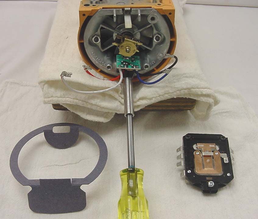
. Tools Required for Stand Mixer Service
Mallet
Electronic Speed
Measuring Device
Hammer
Needle Nose Pliers
Ratchet
11/32” Wrench
#3 Phillips
Bit
Long Flat Screwdriver
Short Flat Screwdriver
#2 Phillips Screwdriver
3/8” Hollow Shank Nut Driver
Other Helpful Tools 5/32” Drift Punch
Watt Meter
1/2” Socket
Awl or Pointed Punch Volt / Ohm Meter
A - 7”
B - 11”
C - 3” E
D - 1 1/2”
E - 45 Degree
Angle E
F - 1 1/2”
G - 3/4” Plywood
(8” x 11”)
B
F
A Cradle - Make your
C own from wood,
D cushion with cloth to
avoid damage to finish
G of mixer.
Appendix - AKITCHENAID
Stand Mixer Service Manual LIT4177310-C 2005 KitchenAid
PROBLEM SOLVING QUICK REFERENCE GUIDE
MIXER PROBLEM MOST LIKELY CAUSE(S) WHAT TO DO / CHECK
Switch lever clicks, but mixer will not Open electrical circuit. Faulty plug.
run or buzz. Faulty power cord.
Faulty speed control plate.
Wire loose from brush holder.
Bad connection between field and cord.
Open circuited armature.
Open circuited field.
Faulty switch ON/OFF.
Bad phase control.
Dirty contacts.
Incorrect brush orientation.
Mixer will not shut off with switch. ON/OFF switch not correctly Check switch control link lever.
adjusted with switch control link
Bowl not held firmly on pedestal Loose clamp disc screws. Tighten the screws.
Bent bowl screw cap. Replace bowl screw cap.
If none available, bend the four lugs or lips
back into position.
Beater strikes bowl or too much Adjusting screw on tongue of Turn the adjusting screw slightly to right or left to
clearance. bottom cover improperly set. adjust clearance. Clearance should be 1/16"
Planetary turns - beater does not revolve. Pinion gear drive pin broken. Remove planetary and take off the pinion gear.
Replace the drive pin.
Mixer runs with a raspy, bumpy noise Bottom cover internal gear teeth Remove the planetary & bottom cover.
at the planetary. worn or broken. NOTE: The complete bottom cover assembly must
be replaced.
Mixer runs with bad vibration rumbling Faulty governor. Replace the governor.
noise and goes to higher speeds. Control plate contacts not going closed.
Adjust the control plate.
Bad phase control. Replace the phase control.
Mixer runs on low speed, but has Bad electrical connections. Check the connections to the control plate.
no power. Repair any loose connections.
Replace the control plate assembly.
Mixer has no power on low speed but "Stir" speed improperly set Remove end cover and reset "stir" speed.
OK on high speed. The planetary should revolve at 60 RPM on "stir"
Faulty governor. Turn switch lever to # 10 position and hold out the
control plate as far as possible. Turn the switch lever
to "OFF". Watch the governor as it recedes when the
armature slows down. If faulty, replace it.
Repeated worm gear failures. Galled attachment gear. Replace attachment hub gear.
Attach hub bearing galled. Replace gear case - motor housing.
Appendix B-1KITCHENAID
Stand Mixer Service Manual LIT4177310-C 2005 KitchenAid
FASTENER REQUIREMENTS
A. FASTENER AND TORQUE VALUES
LISTED BELOW ARE THE FASTENERS AND TORQUE VALUES USED IN THE ASSEMBLY OF THE KITCHENAID.
DESCRIPTION TORQUE IN LBS.
BASE & COLUMN MOUNTING SCREWS (4)(K45) 125/150
BEARING BRACKET ASSEMBLY RETAINING NUTS (2) 15/20
BOWL SCREW CAP RETAINING SCREWS (3)(K45) 24/32
BOWL SPRING MOUNTING SCREWS (2)(K5) 18/23
BOWL SUPPORT MOUNTING SCREWS (2)(K5) 18/23
BRUSH HOLDER CAPS (2) 4/6
BRUSH HOLDER SET SCREWS (2) 3/5
*CONTROL LEVER (SPEED) PIVOT SCREW (1) 18/23
CONTROL PLATE LOCKING NUTS (2) MIN 9
ELECTRIC CORD GROUNDING SCREW (1) 18/23
END COVER RETAINING SCREW (1) 4/7
FEET MOUNTING SCREWS (4)(K5) 4/6
**GEAR CASE RETAINING SCREWS (9) 18/20
LOCK WASHER UNDER 1 GEAR CASE MOUNTING SCREW (K45)(REAR)
LOCK WASHER UNDER 1 BASE MOUNTING SCRW (KSMC50 ONLY)
LOWER GEAR CASE AND COLUMN MOUNTING SCREW (4)(K5) 125/150
AGITATOR SHAFT BEATER DRIVE PIN (1)(KSMC50) 30/40
*GUARD PIN (1)(KSMC50) HAND TIGHT
CIRCUIT BREAKER NUT (1) HAND TIGHT
HEAD LOCK PIVOT SCREW (1)(K45) 18/23
HINGE PIN LOCKING SCREW (1)(K45) 24/33
***STATOR RETAINING NUTS (2) MIN 30
PHASE CONTROL RETAINING SCREW (1) 4/5
PLANETARY GEAR RETAINING SCREW (1)(KSMC50) 18/23
TRIM BANDMOUNTING SCREW (2) 8/10
EUROPEAN GROUND AND FILTER MOUNTING SCREWS MIN 18
STATOR STUD 3/5
*** IF TORQUE GUNS RE SET AT 15/20 LBS.,NUTS MUST BE HAND TORQUED AT LEAST 1/4 OF A TURN WITH A HAND NUT
RUNNER
WORM GEAR BRACKET MOUNTING SCREWS (3) 18/23
BOWL ADJUSTMENT SCREW (K5) 10/12
* BEFORE ASSEMBLY, DIP SPEED CONTROL LEVER PIVOT SCREW AND GURAD PIN INTO A LOCKTITE #271 SOLUTION
Appendix B-1KITCHENAID
Stand Mixer Service Manual LIT4177310-C 2005 KitchenAid
PROBLEM SOLVING QUICK REFERENCE GUIDE
MIXER PROBLEM MOST LIKELY CAUSE(S) WHAT TO DO / CHECK
Mixer runs only on high speed. Control plate spring unhooked. Remove end cover and check control plate spring.
If unhooked, reattach to bottom of the control plate
(check hook on end - rebend if necessary).
Phase control shorted. With the line cord disconnected, pull the T-bar
contacts open and insert a piece of paper between
them so they can not close. Reapply power; the
mixer should just run or buzz trying to run. If it
operates at full speed, the phase control is defective.
Wires connected wrong. Check wiring.
Mixer runs with a jerking clattering Loose connections on the Check connections on the control board to make
noise on low speed. control board. certain they are tight.
Tight shim on vertical shaft between Tight bearing. First remove the planetary to check the beater shaft
planetary and lower gear case. bearing in the planetary. If the beater shaft can be
See item "V" - Section 4 easily moved back and forth with a twisting effort,
it is satisfactory. If it binds, replace the planetary.
If it checks okay, recheck the mixer without it. If the
mixer still uses excessive watts, it must be
disassembled and the other bearings checked.
Loud rumbling or howling noise. Worn spherical bearing on the Remove bearing bracket and replace.
end of the armature shaft.
Worn armature thrust bearing. Replace the thrust ball bearing on the armature.
Mixer runs, but will not come up to high Tight bearing, if no smoke is First remove the planetary to check the beater shaft
speed. Has power, but labors and uses apparent. bearing in the planetary. If the beater shaft can be
excessive watts. easily moved back and forth with a twisting effort,
it is satisfactory. If it binds, replace the planetary.
If it checks okay, recheck the mixer without it. If the
mixer still uses excessive watts, it must be
disassembled and the other bearings checked.
Armature shimmed too tight. Overheated armature, if the mixer Dissemble the motor and replace the armature
See item "J "- Section 3 smokes. assembly.
Mixer will not shut off with switch lever. Switch not correctly adjusted with Bend the fixed contact on the control board until the
Appendix B-2You can also read