Touch Screen Flush-mount Room Thermostats with KNX Communications - RDF880KN..
←
→
Page content transcription
If your browser does not render page correctly, please read the page content below
RDF880KN.. with temperature display           RDF880KN.. with % r.h. display

Touch Screen Flush-mount Room Thermostats
with KNX Communications
RDF880KN..
Under Floor Heating (UFH) control application
with an additional HMI for Variable Refrigerant Flow (VRF) commands via KNX S-Mode

Basic documentation

A6V12318532_en--_a
2021-03-22                                                                         Smart Infrastructure

Table of contents
                       1.        About this document .............................................................................. 4
                       1.1       Revision history ......................................................................................... 4
                       1.2       Reference documents ............................................................................... 4
                       1.3       Before you start ......................................................................................... 5
                       1.3.1     Copyright ................................................................................................... 5
                       1.3.2     Quality assurance ..................................................................................... 5
                       1.3.3     Document use/request to the reader ........................................................ 5
                       1.4       Target audience, prerequisites .................................................................. 6
                       1.5       Conventions used in this document .......................................................... 6
                       1.6       Glossary .................................................................................................... 6
                       2.        Summary .................................................................................................. 7
                       2.1       Types ......................................................................................................... 7
                       2.2       Ordering .................................................................................................... 7
                       2.3       Functions ................................................................................................... 7
                       2.4       User interface ............................................................................................ 9
                       2.5       Integration with KNX bus......................................................................... 10
                       2.6       Equipment combinations ......................................................................... 11
                       2.7       Accessories ............................................................................................. 12
                       3.        Functions ............................................................................................... 13
                       3.1       Room temperature control ...................................................................... 13
                       3.2       Operating modes ..................................................................................... 14
                       3.2.1     Influencing the operating mode ............................................................... 18
                       3.3       Room temperature setpoints ................................................................... 20
                       3.3.1     Description .............................................................................................. 20
                       3.3.2     Setting and adjusting setpoints ............................................................... 21
                       3.4       Applications overview .............................................................................. 22
                       3.4.1     Application: Under Floor Heating & VRF HMI ......................................... 24
                       3.4.2     Application: Under Floor Heating & VRF HMI ......................................... 25
                       3.4.3     Applications for heating ........................................................................... 26
                       3.5       Additional functions ................................................................................. 27
                       3.6       Control sequences (UFH only) ................................................................ 29
                       3.7       Control outputs (UFH only) ..................................................................... 30
                       3.8       Fan control via VRF HMI only ................................................................. 31
                       3.9       Multifunctional input, digital input ............................................................ 33
                       3.10      Handling faults ........................................................................................ 34
                       3.11      KNX communications .............................................................................. 35
                       3.11.1    S-Mode .................................................................................................... 35
                       3.11.2    Send heartbeat and receive timeout ....................................................... 35
                       3.11.3    Startup ..................................................................................................... 35
                       3.11.4    Fault function on KNX ............................................................................. 36
                       3.12      Communication objects (S-Mode) ........................................................... 37
                       3.13      Control parameters ................................................................................. 39
                       3.13.1    Setting parameters using the local HMI .................................................. 39
                       3.13.2    Setting and downloading parameters using the tools ............................. 40
                       3.13.3    Service level parameters......................................................................... 41
                       3.13.4    Expert level parameters with diagnostics and test .................................. 42
2 / 60
Siemens                RDF880KN.. Basic documentation                                                                 A6V12318532_en--_a
Smart Infrastructure   Contents                                                                                               2021-03-22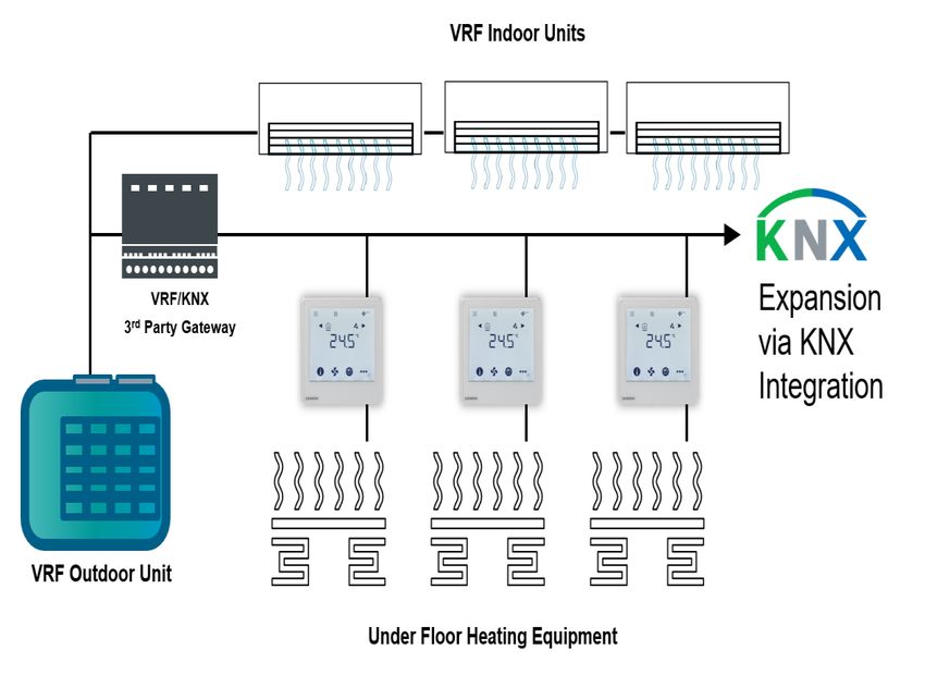
4.        Handling ................................................................................................. 44
                       4.1       Mounting and installation ........................................................................ 44
                       4.2       Commissioning........................................................................................ 45
                       4.3       Operation ................................................................................................ 48
                       4.3.1     Alarm/Service reminder .......................................................................... 48
                       4.4       Disposal .................................................................................................. 48
                       5.        Supported KNX tools ............................................................................ 49
                       5.1       ETS ......................................................................................................... 49
                       5.1.1     Commissioning – downloading using ETS ............................................. 49
                       5.1.2     Parameter settings in ETS ...................................................................... 50
                       6.        Connection ............................................................................................ 51
                       6.1       Connection terminals .............................................................................. 51
                       6.2       Connection diagrams .............................................................................. 52
                       7.        Mechanical design ................................................................................ 53
                       7.1       General ................................................................................................... 53
                       7.2       Dimensions ............................................................................................. 54
                       8.        Technical data ....................................................................................... 57

                                                                                                                                          3 / 60
Siemens                RDF880KN.. Basic documentation                                                                A6V12318532_en--_a
Smart Infrastructure   Table of contents                                                                                     2021-03-22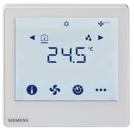
1.        About this document
                             1.1       Revision history
   Edition      Date           Changes                                                 Section     Pages
   1            2021-03-10     First version                                           All         All

                             1.2       Reference documents
Subject                      Ref    Doc no.           Description
Touchscreen flush-mount      [1]    A6V11272225       Operating Instructions
room thermostats with KNX    [2]    A6V11282546       Data Sheet
communications
KNX Manual                   [3]    Handbook for Home and Building Control – Basic Principles
                                    (EN:
                                    https://my.knx.org/shop/product?language=en&product_type_category=book
                                    s&product_type=handbook
                                    DE:
                                    https://my.knx.org/shop/product?language=de&product_type_category=book
                                    s&product_type=handbook)
Synco and KNX (see           [4]    CE1N3127          KNX bus, Data Sheet
www.siemens.com/synco)       [5]    CE1P3127          Communication via the KNX bus for Synco 700, 900 and
                                                      RXB/RXL, Basic Documentation
                             [6]    XLS template in Planning and commissioning protocol, communication
                                    HIT               Synco 700
                             [7]    CE1N3121          RMB795B central control unit, Data Sheet
                             [8]    CE1Y3110          KNX S-mode data points
                             [9]    --                Product data for ETS
                             [10]   CE1J3110          ETS product data compatibility list
                             [11]   0-92168en         Synco Application Manual
Desigo                       [12]   CM1Y9775          Desigo RXB integration – S-mode
Engineering Documents        [13]   CM1Y9776          Desigo RXB/RXL integration – Individual Addressing
                             [14]   CM1Y9777          Third-party integration
                             [15]   CM1Y9778          Synco integration
                             [16]   CM1Y9779          Working with ETS

4 / 60
Siemens                      RDF880KN.. Basic documentation                              A6V12318532_en--_a
Smart Infrastructure                                                                             2021-03-22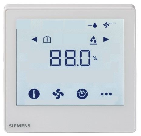
1.3        Before you start
                          1.3.1     Copyright

                       This document may be duplicated and distributed only with the express permission
                       of Siemens, and may be passed only to authorized persons or companies with the
                       required technical knowledge.

                          1.3.2     Quality assurance

                       This document was prepared with great care.
                       • The contents of this document are checked at regular intervals.
                       • Any corrections necessary are included in subsequent versions.
                       • Documents are automatically amended as a consequence of modifications and
                           corrections to the products described.
                       Please make sure that you are aware of the latest document revision date.
                       If you find lack of clarity while using this document, or if you have any criticisms or
                       suggestions, please contact the Product Manager in your nearest branch office.
                       The addresses of the Siemens Regional Companies are available at
                       www.buildingtechnologies.siemens.com.

                          1.3.3     Document use/request to the reader

                       Before using our products, it is important that you carefully read the entire
                       documents supplied with or ordered within the products (equipment, applications,
                       tools, etc.).
                       We assume that persons using our products and documents are authorized and
                       trained appropriately and have the technical knowledge required to use our
                       products as intended.
                       More information on the products and applications is available at:
                       • On the intranet (Siemens employees only) at
                           https://workspace.sbt.siemens.com/content/00001123/default.aspx
                       • From the Siemens branch office near you
                           www.buildingtechnologies.siemens.com or from your system supplier
                       • From the support team at headquarters fieldsupport-zug.ch.sbt@siemens.com if
                           there is no local point of contact.

                       Siemens assumes no liability to the extent allowed under the law for any losses
                       resulting from a failure to comply with the aforementioned points or for the
                       improper compliance of the same.

                                                                                                           5 / 60
Siemens                RDF880KN..   Basic documentation                                      A6V12318532_en--_a
Smart Infrastructure                                                                                 2021-03-22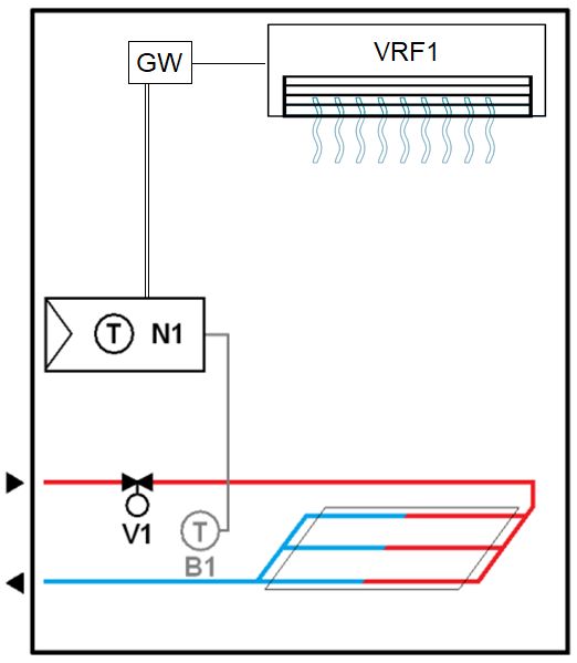
1.4       Target audience, prerequisites

                       This document assumes that users of the RDF880KN..room thermostats are
                       familiar with the ETS tools and can use them.
                       It is also assumed that these users are aware of the specific conditions associated
                       with KNX.
                       In most countries, specific KNX know-how is conveyed through training centers
                       certified by the KNX Association (see www.knx.org/).
                       For reference documentation, see section 1.2.

                       1.5       Conventions used in this document

                       Throughout this document, parameters are specified as P[parameter number].
                       For example, P30.

                       1.6       Glossary

                       The inputs, outputs and parameters of an application can be influenced in various
                       ways. These are identified by the following symbols in this document:

         ETS           Parameters identified by this symbol are set using ETS.

STOP      Note!        The setting of RDF880KN... parameters is only supported by the following
                       tool versions:
                          – ETS4 or higher

                       Inputs and outputs identified by this symbol communicate with other KNX devices.
                       They are called communication objects (CO).
                       The communication objects of the RDF880KN… room thermostats work in S-Mode
                       mainly. These objects are described accordingly.

                       A list of the parameters is shown in section 3.13.

6 / 60
Siemens                RDF880KN.. Basic documentation                                    A6V12318532_en--_a
Smart Infrastructure                                                                             2021-03-22
2. Summary
2.1 Types
Control outputs
Product no. Stock no. Operating voltage Suitable conduit box
On/Off
RDF880KN/NF S55770-T409 12) Square types only1)
AC 230 V
RDF880KN S55770-T415 12) Round/square types
1)
Additional ARG800.1 mounting frame is required to complete the installation and ARG800.1
must be ordered separately. See section 2.7.
2)
On/Off output with potential free input from AC 24…230 V
2.2 Ordering
• When ordering, please specify product no., SSN no. and name:
e.g.: RDF880KN (S55770-T415) room thermostat.
• Separate mounting frames (ARG800.1) must be ordered for RDF880KN/NF
installation (see section 2.7).
• Order valve actuators separately.
2.3 Functions
Applications RDF880KN... is a 2-in-1 design to provide easy-to-understand HMI for any existing
VRF system installed in residential homes and apartments where Under Floor
Heating (UFH) room thermostat may be required at the same time.
The required applications are selected and activated during commissioning via the
following tools:
• ETS
• Local DIP switch and the HMI (see table below):
• Under Floor Heating (UFH) unit with an On/Off control output
• VRF HMI Room unit to send commands to a VRF indoor unit via a KNX/VRF
gateway
• Under Floor Heating unit with a VRF HMI function
Download via ETS
(All in OFF positions)
UFH only
VRF HMI only
VRF HMI and UFH
7 / 60
Siemens RDF880KN.. Basic documentation A6V12318532_en--_a
Smart Infrastructure 2021-03-22General Functions ● Room temperature control via a built-in or external room temperature sensor
● Calibrations for both internal temperature and relative humidity sensors
● Display of current room temperature or setpoint in °C
● Minimum and maximum limitation of room temperature setpoint
● Fan speed adjustment, auto, manual (up to 7 speeds)
● Selections of VRF operating mode:
→ AUTO, HEAT, COOL, FAN and Dehumidify
● Selections of UFH operating mode:
→ Comfort and Protection
● Energy saving (Economy mode) for both VRF and UFH
● Key lock function: unlock, total lock and setpoint lock
● 2 multifunctional inputs, freely selectable for:
- External room temperature or return air temperature sensor
- Window contact
- Fault input
- Monitor input for temperature sensor or switch state
● Floor heating temperature limitation
● Display of outdoor temperature and time scheduling via KNX bus
● Reload factory settings for commissioning and control parameters
Optional: enable / disable via parameters
● Relative humidity display via a built-in humidity sensor
● Auto-swing selection: auto swing or fix at any position (up to 10)
● Delay off timer: up to 23 hour operations
● Chinese text display for 4 navigation icons
Features • Backlit display
• AC 230 V operating voltage
• Potential-free contact (SPDT) for boiler applications
Type of mounting/ • RDF880KN: Round CEE/VDE conduit boxes, with minimum 60 mm diameter or
suitable conduit boxes recessed square conduit boxes with 60.3 mm fixing centers, minimum 40 mm
depth
• RDF880KN/NF: Recessed square conduit boxes with 60.3 mm fixing centers,
minimum 40 mm depth
8 / 60
Siemens RDF880KN.. Basic documentation A6V12318532_en--_a
Smart Infrastructure 2021-03-222.4 User interface
The RDF880KN… room thermostats have a touchscreen (segment type) user
interface.
To start any operation or change settings, touch the screen to display all available
operating icons available in Selection Screen mode. Ten seconds after the last
operation, the thermostat returns to Screen Saver mode.
Display STATUS &
OPERATION of the
room thermostat
SELECTION of
available information and
VRF fan modes
INFORMATION
1st line: temperature or
humidity, values of
parameters
2nd line: parameters and
alarms
Both sides: STATUS
ADJUSTMENT for temperature setpoint, fan speed, operating modes of VRF and
Floor Heating, more INFO and settings (for example, Alarm, Delay Off Timer, etc.)
Status symbols: Operational icons:
Economy active Alarm / Service active Increment, decrement OR selection
Delay timer active Key lock active
Selection OR move to next items
Temperature, relative humidity OR
Floor heat active Fan active
parameter values, etc.
VRF operating modes Parameters OR password, etc.
Selection symbols:
Setpoint mode (temperature only)
Indoor temperature VRF fan speed
Fan mode OR fan speed mode
Outdoor temperature VRF auto-swing
VRF & floor heat operating modes
Relative humidity More info & settings
Operations Operations Function
Touch to select setpoint mode; adjust temperature value using +/–.
Touch to select fan mode; adjust fan speed using +/ –.
Touch to select operating mode; select ON/ECO/OFF or
AUTO/HEAT/COOL/FAN/Dehumidification using +/ –.
Touch to select the INFO screen, display room & outdoor temperatures
using / if available.
to select the desired H/C control sequence using +/– if manual H/C
changeover (P01 = 2) is selected.
to display alarms if the icon is displayed; use / icon to select
different alarms for viewing.
Touch for 5 seconds to select programming mode (KNX).
Touch for 5 seconds to select parameter mode (Service/Expert level).
9 / 60
Siemens RDF880KN.. Basic documentation A6V12318532_en--_a
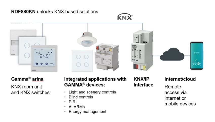
Smart Infrastructure 2021-03-222.5 Integration with KNX bus
The touchscreen room thermostats can be integrated as follows:
• Into Synco living using group addressing (ETS)
• Into Desigo using group addressing (ETS) or individual addressing
• Into third-party systems using group addressing (ETS)
The following KNX functions are available:
• Central time program and setpoints. For example, when using the RMB795B
central control unit.
• Outdoor temperature or time of day displayed on thermostat using the bus
• Remote operation and monitoring. For example, using the RMZ792-B bus
operator unit.
• Remote operation and monitoring with web browser using the OZW772 web
server.
• Maximum energy efficiency due to exchange of relevant energy information. For
example, with Synco 700 controllers, heating demand, cooling demand.
• Alarming (such as, external fault contact, condensation, or clean filter).
• Monitoring input for temperature sensor or switch.
Engineering and commissioning can be done using…
• local DIP switches/HMI
• ETS
Desigo and third-party The KNX communicating devices can be integrated into the Siemens building
systems automation and control systems (BACS) Desigo or third-party systems. For
integration, you can use either S-Mode (group addressing) or individual
addressing.
10 / 60
Siemens RDF880KN.. Basic documentation A6V12318532_en--_a
Smart Infrastructure 2021-03-222.6 Equipment combinations
Description Product no. Data Sheet
Cable temperature sensor or
changeover sensor, cable length
QAH11.1 a) 1840
2.5 m
NTC (3 k at 25 °C)
Room temperature sensor
QAA32 1747
NTC (3 k at 25 °C)
Cable temperature sensor,
cable length 4 m QAP1030/UFH 1854
NTC (3 k at 25 °C)
On/Off actuators Electromotoric On/Off actuator SFA21.. 4863
Electromotoric On/Off valve and
actuator (only available in AP, MVI../MXI.. A6V11251892
UAE, SA and IN)
Zone valve actuator (only
SUA.. 4832
available in AP, UAE, SA and IN)
Thermal actuator (for radiator
STA23.. 4884
valve)
Thermal actuator
STP23.. 4884
(for small valves 2.5 mm)
Damper actuator GDB.. 4634
Damper actuator GSD.. 4603
Damper actuator GQD.. 4604
Rotary damper actuator GXD.. 4622
Notes: a)both QAH11.1 and QAP1030/UFH are for floor heating applications, such as
temperature limitation controls. QAP1030/UFH has a special head and 4 m long
that is more suitable for such application.
Refer to data sheets of the actuators for the maximum number of parallel
operation.
11 / 60
Siemens RDF880KN.. Basic documentation A6V12318532_en--_a
Smart Infrastructure 2021-03-222.7 Accessories
Designation Product no. / SSN Data sheet
Single mounting frame*), Ivory White ARG800.1 /
S55770-T370
--
KNX Power supply 160 mA (Siemens BT LV) 5WG1 125-1AB02 --
KNX Power supply 320 mA (Siemens BT LV) 5WG1 125-1AB12 --
KNX Power supply 640 mA (Siemens BT LV) 5WG1 125-1AB22 --
*)
See the dimensions of mounting frame on page 56. ARG800.1 is for RDF880KN/NF only.
12 / 60
Siemens RDF880KN.. Basic documentation A6V12318532_en--_a
Smart Infrastructure 2021-03-223. Functions
3.1 Room temperature control
General note: Information for setting the control parameters (e.g. P02) is described in
Parameters section 3.13.
Room temperature The thermostat acquires the room temperature using its built-in sensor, external
control room temperature sensor (QAA32), or external return air temperature sensor
(QAH11.1), and maintains the setpoint by delivering actuator control commands to
the heating equipment. The following control outputs are available:
• SPDT relay On/Off control with free potential free input AC 24…230 V
The switching differential or proportional band is 1 K for heating mode (adjustable
via P30).
In addition, VRF HMI can be used for sending setpoint adjustment commands to
corresponding indoor VRF unit via a third party KNX/VRF gateway and the
temperature control is determined by the values between the room temperature
detected by VRF indoor unit and temperature setpoint received from RDF880KN…
Display Use and to select and display either the acquired room temperature or
relative humidity. Both values are obtained via built-in sensors. There is no
humidity control function in the unit. The relative humidity value is displayed to
advise the users to switch the VRF operating mode to Dehumidification (if
available) to maintain a comfort environment.
The temperature display can be set to acquire room temperature or the Comfort
setpoint, which is selected via P06. The factory setting displays the current room
temperature and relative humidity.
Use P05 and P23 to calibrate the room temperature value in degree Celsius °C
and the relative humidity value in % respectively while F is not available in this
unit.
The acquired room temperature (built-in or external sensor) is also available as
information on the bus.
Room temperature
/
If the outdoor temperature is available via KNX bus, then use and to select
the outdoor temperature. The temperature value is a display-only information.
Outdoor temperature
using the bus
In S-Mode, the corresponding communication object needs to be bound with a
KNX sensor device for obtaining outdoor temperature.
13 / 60
Siemens RDF880KN.. Basic documentation A6V12318532_en--_a
Smart Infrastructure 2021-03-223.2 Operating modes
The thermostat's operating modes can be influenced in different ways (see below).
Specific heating and cooling setpoints are assigned to each operating mode.
Comfort and Economy In Comfort or Economy mode, the Screen Saver mode normally displays the room
modes temperate as follows:
When users touch the temperature display, the normal display shows (see the
figure on the left side with both UFH and VRF applications below).
Touch the icon to display the current VRF operating mode. Use +/– to change
the VRF operating mode.
If P02 = 2, the following operating mode for UFH can be selected via or :
Comfort (ON), Economy (ECO)
14 / 60
Siemens RDF880KN.. Basic documentation A6V12318532_en--_a
Smart Infrastructure 2021-03-22Protection mode Under the normal display (see above section), press and use +/– to select
OFF to turn off the unit. In Protection mode, the Screen Saver mode displays OFF:
When users touch OFF, the thermostat changes to ON first and then returns to
Comfort or Economy mode. Then it displays the setpoint adjustment screen.
Touch +/– to adjust the room temperature setpoint.
Notes: • In Economy mode, the icon does not display since the setpoint is not
adjustable.
• In Protection mode, both the and icons do not display since both
setpoint and fan speed are not adjustable.
15 / 60
Siemens RDF880KN.. Basic documentation A6V12318532_en--_a
Smart Infrastructure 2021-03-22The thermostat sends the effective room operating mode on the bus.
Room operating mode: The following operating modes are available for UFH application only. For VRF
State HMI, ON and OFF are used instead of Comfort and Protection modes.
Auto Timer In Auto Timer mode, the operating mode is set using the bus only.
If no time scheduler is present, Auto Timer is replaced by Comfort.
Note that for this unit, the use of Auto Timer mode is related to UFH application
mostly.
Comfort In Comfort mode, the thermostat maintains the Comfort setpoint.
This setpoint can be defined using P08, P09 and P10. It also can be locally
adjusted using +/– after touching the icon or using the bus. The setpoint in
Comfort mode is shared by both UFH and VRF applications.
In Comfort mode, touch the icon to set the fan speed of the VRF indoor unit to
either automatic (A - AUTO) or manual fan speed (1/2/3).
Economy In Economy mode, the UFH and VRF applications work differently.
The thermostat switches to Economy mode when users touch the icon and use
or to select ON (Comfort) or ECO mode (available if P02 is set to 2).
For UFH, when ECO mode is selected, a fixed heating setpoint is used for the
heating control to reduce energy consumption when the area is unoccupied or
during sleeping time. The heating setpoint is defined via P11.
For VRF, when ECO mode is selected, the low power mode is used. Therefore,
ECO mode is not recommended for VRF system with multiple indoor units.
Normally, a master VRF room unit in the system is used to select the ECO mode
for all indoor units connected to the same system. i.e. others are slave room units
and not able to select ECO mode.
Due to the complexity of ECO mode, it is not recommended to enable ECO mode
(i.e. P02 = 2) when both VRF and UFH applications run at the same time in one
RDF880KN.. unit. (see Dip switch settings in Functions)
16 / 60
Siemens RDF880KN.. Basic documentation A6V12318532_en--_a
Smart Infrastructure 2021-03-22Protection The thermostat switches to Protection mode by touching the icon and using +/-
to select OFF.
For UFH application, OFF means frost protection (factory setting 8 °C, can be
disabled or changed via P65). For VRF application, it means turning off the indoor
unit.
If RDF880KN.. is set with both UFH and VRF applications via DIP switch, users
can press icon once and use +/- to select:
1. to turn on UFH ( ) application only
2. to turn on VRF ( ) application only
3. to turn on both UFH ( ) and VRF ( ) applications
4. OFF to turn off both applications
Delay Off Timer When P28 = ON (enable), the symbol appears next to the icon.
Press icon twice and use +/- to set the delay-off time for the unit. Then, press
the hour location (i.e. x h) to confirm the required time and return to the normal
display mode. The Delay Off Timer mode icon is displayed when the count-down
starts.
To cancel, set the delay-off timer to 0 h.
17 / 60
Siemens RDF880KN.. Basic documentation A6V12318532_en--_a
Smart Infrastructure 2021-03-223.2.1 Influencing the operating mode
Priority of operating The following table shows the priorities of different interventions.
mode interventions A lower number means a higher priority.
Priority Description Remark
Commissioning In parameter setting mode (highest priority), you can command an operating
mode independent of all other settings or intervention using bus and local input.
Protection mode Protection mode is, sent by a time scheduler
using the bus from It cannot be overridden by the user, or by the window contact.
time scheduler
Window contact If the contact is closed (i.e. window open), the operating mode changes to
Protection. This overrides the operating mode on the thermostat.
"Window state" "Window state" has the same effect as the local window contact.
using the bus
Note: Only one input source must be used, either local input X1/X2 or KNX bus.
VRF operating Touch the icon to select the VRF operating mode using +/–.
mode icon
Operating mode Touch the icon to select the Comfort (ON) or ECO mode using or .
icon Note: P02 = 2 only.
Operating mode Both VRF operating modes or operating mode can be changed using the bus.
using the bus
Temporarily Touch the icon and use or to set operating mode from Economy to
extended Comfort Comfort temporarily if...
mode using – Economy was sent using bus
operating mode – Extended Comfort period > 0 (P68)
icon The last option selected is always used, either locally or using bus.
(UFH only)
Auto Timer mode If a time scheduler is available, e.g. from the central control unit, Auto Timer mode
with time scheduler is active. The thermostat automatically changes between Comfort and Economy
using the bus mode according to the time scheduler using the bus.
The display shows the Auto Timer mode icon .
Touch the operating mode icon to change to another operating mode.
Note: When you are in the Auto Timer mode, and you change the operating mode, the
icon (manual override) displays in place of the icon, indicating that a schedule
being overridden.
Default fan speed in Auto Timer mode is automatic.
Behavior when bus Each time the time scheduler sends a new operating mode (switching event), the
sends new operating thermostat’s operating mode is set back to Auto Timer. This ensures that the room
mode temperature is maintained according to the time schedule.
Precomfort using the If the time scheduler sends the Pre-comfort mode, it will be switched to Economy
bus (factory setting) or Comfort (selectable via P88).
Behavior when bus If Protection mode is set by the time scheduler, no intervention is possible neither
sends Protection by users, window contact or presence detector. The screen displays OFF.
18 / 60
Siemens RDF880KN.. Basic documentation A6V12318532_en--_a
Smart Infrastructure 2021-03-22Window contact The thermostat can be forced into Protection mode when the window is opened.
The contact can be connected to a multifunctional input X1, X2. Set P38 or P40 to
3. User operations are ineffective and OFF is displayed if the window contact is
active.
The “window contact” function is also available using the KNX signal "Window
state", e.g. from a KNX switch.
Room operating mode:
Window state
If the window contact is active, touch the icon and OFF flashes on the LCD.
Note: Only one input source can be used, either a local input X1/X2 or the KNX bus.
User operations are ineffective and OFF is displayed if the operating mode
“window contact” is active, or if "Window state" is sent using the bus.
Temporary timer to Comfort mode can be temporarily extended (e.g. working after business hours or
extend the Comfort on weekends) when the thermostat is in Economy mode. Using the operating
mode mode icon and press or to select ON for Comfort mode for the period
preset via P68.
Touch the icon again and use or to change to ECO mode to stop the timer.
The following conditions must be fulfilled:
• Time scheduler using the bus is Economy mode.
• P68 (extend Comfort period) is greater than 0.
During the temporary Comfort mode extension, the icon appears.
If P68 (extend Comfort period) = 0, extended Comfort cannot be activated.
Note: Auto Timer mode and Pre-comfort mode are not recommended for VRF
applications. It is only suitable for UFH applications with KNX bus.
19 / 60
Siemens RDF880KN.. Basic documentation A6V12318532_en--_a
Smart Infrastructure 2021-03-223.3 Room temperature setpoints
3.3.1 Description
Setpoint mode Touch the icon when it is available on the display and press +/– to adjust the
desired room temperature setpoint.
Comfort mode The factory setting for the Comfort basic setpoint is 21 °C. It can be changed in the
thermostat’s EEPROM using P08 or the bus with the communication object
"Comfort basic setpoint". The last option selected is always used.
The Comfort setpoint can be adjusted using +/–, or the bus from a remote device
such as a touch panel, or operating unit. The last option selected is always used.
The same Comfort setpoint is shared by both VRF HMI and UFH applications for
control purpose.
Temporary setpoint If the "Temporary setpoint" function is enabled using P69, the Comfort setpoint is
set back to the Comfort basic setpoint stored in P08 when the operating mode
changes. This function works for UFH application only.
Setpoint limitation For comfort or energy saving purposes, the setpoint setting range can be limited to
a minimum (P09) and maximum (P10).
P09 < P10 • If the minimum limit P09 is set lower than the maximum limit P10, heating and
(Comfort concept) cooling setpoints can be adjustable between these two limits. Note that for
UFH application, only heating setpoint is relevant.
• The customer adjusts the desired setpoint and the thermostat controls the
room temperature accordingly.
Example: Cooling setpoint adjustable: 18…25 °C
Heating setpoint adjustable: 18…25 °C
5°C 18°C 25°C 40°C
P09 P10 Note that cooling setpoint applied to
VRF only.
Economy mode Use P11 to adjust the Economy mode heating setpoint for UFH application.
The heating setpoint is factory-set to 15 °C.
Protection mode Use P65 to adjust the Protection mode heating setpoint for UFH application.
The heating setpoint is factory-set to 8 °C (frost protection) and to OFF for cooling.
Caution If a setpoint (Economy or Protection) is set to OFF, the UFH application in the room
thermostat does not control the room temperature in heating mode. This means
that there is no protective heating function and there exists a risk of frost in heating
mode!
The Economy setpoints are accessible at the Service level (P11) or via tools (ACS
or ETS). The Protection setpoints are accessible at the Expert level (P65).
20 / 60
Siemens RDF880KN.. Basic documentation A6V12318532_en--_a
Smart Infrastructure 2021-03-223.3.2 Setting and adjusting setpoints
Room temperature setpoints can be
– set during commissioning
– adjusted during operation
The source can be
• the local HMI
Comfort basic setpoint • a tool
Comfort setpoint • a central control unit
Economy heating
setpoint The thermostat stores the setpoints…
Economy cooling • in EEPROM in the form of parameters
setpoint • in the runtime memory
The table below shows the interrelations:
Setpoint setting Stored in thermostat’s
EEPROM
Commissioning Input LTE-Mode Input S-Mode
– HMI
– Tool download
Comfort basic setpoint Setpoints heating Comfort basic P08 Comfort basic setpoint
setpoint
Setpoint Economy heating Setpoints heating Setpoints heating P11 Economy heating
Setpoint Protection heating P65 Protection heating
Current runtime Setpoint New current
setpoints in adjustment runtime setpoints
thermostat in thermostat
Input LTE- Input S-Mode3) Local ope-
Mode2) ration
Comfort setpoint Setpoint shift H Comfort setpoint +/– Comfort setpoint
Economy heating Setpoint shift H Economy heating
Protection heating Protection heating
Effective room Current setpoint (used by the UFH heating thermostat for room
operating mode temperature control)
1) Only required for heating applications (see section 3.4.3.
2) LTE-Mode: shift is added to the local shift.
3) S-Mode: the last option selected is always used, either S-Mode input or local
operation.
21 / 60
Siemens RDF880KN.. Basic documentation A6V12318532_en--_a
Smart Infrastructure 2021-03-22The current setpoint (used by the thermostat for room temperature control) is
available on the bus for use by the central control unit.
Current setpoint
General notes: • The supported communication objects are different in LTE-Mode and S-Mode.
• Making changes using the local HMI or tool have the same priority.
• Setting the Comfort basic setpoint resets the runtime Comfort setpoint to the
basic setpoint.
Notes on setpoint • Central setpoint shift is used for summer or winter compensation.
adjustment (LTE-Mode • Setpoint shift does not affect the parameter setpoints in P08 and P11.
with Synco only) • Local shift and central shift are added together.
• Only applies to Comfort and Economy setpoints. Protection setpoints are not
shifted centrally.
• The current setpoints for heating are limited by the Protection setpoint. If the
Protection setpoint is OFF, min. 5 °C and max. 40 °C are used.
• The setpoints for heating of the same operating mode have a minimum
distance of 0.5 K between them.
• The result of local and central shift, together with the room operating mode, is
used by the thermostat for room temperature control (current setpoint).
Setpoint priority, • The room thermostat always adopts the received setpoints from the controller
Setpoint Master RMB RMB795B. Thus the Comfort setpoints locally adjusted on the thermostats are
overwritten by the Comfort setpoints of the room group (e.g. every 15 minutes).
On the RMB795B central control unit (software version 2.0 or higher), you can
define the conditions required for the unit to forward the setpoints:
• Always (every 15 minutes)
• Not in Comfort mode
• Only when changed
See "Setpoint priority" and "Setpoint master" functions on the RMB795B.
3.4 Applications overview
Local configuration The thermostats support the following applications, which can be configured using
the DIP switches inside the front panel of the unit or a commissioning tool.
1. Set applications via DIP switches.
2. After the thermostat is first DIP SW
powered up, the Wizard function Positions Applications
will provide basic control 1 2
parameters setup ON OFF UFH only
OFF ON VRF only
3. The display depends on the ON ON VRF + UFH
selected application.
→ Go to the setting mode and
configure the basic control parameters
22 / 60
Siemens RDF880KN.. Basic documentation A6V12318532_en--_a
Smart Infrastructure 2021-03-22Remote configuration All DIP switches must be set to OFF (remote configuration, factory setting) in order
to select an application using the commissioning tool.
COMMISSIONING: Download via ETS
1. DIP switch setting 2. First power up
All in OFF positions Press to turn ON
3. Touch & hold this 4. Ready for downloading
icon > 5 s to enter address & application
Programming mode
Touch “ON“ to exit
23 / 60
Siemens RDF880KN.. Basic documentation A6V12318532_en--_a
Smart Infrastructure 2021-03-223.4.1 Application: Under Floor Heating & VRF HMI
Application, DIP Switches, Diagram
Under Floor Heating & VRF HMI
V1 Heating valve actuator B1 Return air temperature sensor or external
room temperature sensor (optional)
GW 3rd Party KNX/VRF Gateway N1 Thermostat
VRF1 One or more VRF indoor units
Note: The VRF outdoor unit and KNX power supply unit are not shown in the diagram.
Since all VRF brands have their own communication protocols between their own remote control unit (RCU) and VRF
equipment (e.g. indoor or outdoor units), RDF880KN... can send all standard KNX commands (S-Mode KNX objects) via
the KNX bus to a third party KNX/VRF gateway (as a protocol converter) and then communicate indirectly with the VRF
indoor or outdoor units. Effectively, it works similarly like a RCU of a VRF system.
24 / 60
Siemens RDF880KN.. Basic documentation A6V12318532_en--_a
Smart Infrastructure 2021-03-223.4.2 Application: Under Floor Heating & VRF HMI
Application, DIP Switches, Diagram
VRF HMI
GW 3rd Party KNX/VRF Gateway N1 Thermostat
VRF1 One or more VRF indoor units
Note that RDF880KN... cannot replace all functions of the remote control unit (RCU) of the VRF system but it can provide the daily
operations to cover the following typical VRF functions:
• Temperature - provide current room temperature value
- adjust temperature setpoint
• Fan - select auto or manual speed up to 7 levels
- select auto swing or fixed swing positions
• Operation - set to AUTO, HEAT, COOL, FAN and Dehumidification
25 / 60
Siemens RDF880KN.. Basic documentation A6V12318532_en--_a
Smart Infrastructure 2021-03-223.4.3 Applications for heating
Application, DIP Switches, Diagram
UFH, Radiator
Room thermostat controls the valve of the radiator Room thermostat controls the valve for the floor heating
application application
Room thermostat with direct control of a gas-fired Room thermostat with direct control of a gas-fired floor-
wall-hung boiler standing boiler
Room thermostat with direct control of a heat Room thermostat with direct control of hydronic floor
pump (pre-controlled by manual mixing valve) heating system
F1 Thermal reset limit thermostat N1 Room thermostat
F2 Safety limit thermostat V1 2-port valve
M1 Circulating pump V2 Mixing 3-port valve with manual adjustment
V3 Magnetic valve
26 / 60
Siemens RDF880KN.. Basic documentation A6V12318532_en--_a
Smart Infrastructure 2021-03-223.5 Additional functions
External/return air The thermostat acquires the room temperature through its built-in sensor, external
temperature sensor room temperature sensor (QAA32), or external return air temperature sensor
(QAH11.1) connected to multifunctional input X1 or X2. Input X1 or X2 must be
configured accordingly. See section 3.9.
Minimum output Limit the On/Off switching cycle to protect the HVAC equipment (e.g. a
ON-time/OFF-time compressor) and to reduce wear and tear. The minimum output ON-time and OFF-
time for 2-position control output can be adjusted from 1 to 20 minutes using P48
and P49.
This function applies to UFH only and the factory setting is 1 minute.
Re-adjusting the setpoint or heating/cooling mode changeover immediately results
in calculation of the output state; the outputs may not hold the minimum 1-minute
On/Off time.
If P48 or P49 is set to above 1 minute, the minimum On/Off time for the control
output is maintained as set, even if the setpoint or changeover mode is readjusted.
Floor temperature The floor temperature should be limited for two reasons: Comfort and protection of
limitation function the floor.
The floor temperature sensor, connected to multifunctional input X1 or X2, acquires
the floor temperature. If it exceeds the parameterized limit (P51), the heating valve
is fully closed until the floor temperature drops to a level 2 K below the
parameterized limit.
Factory setting of this function is “OFF” (disabled).
Input X1 or X2 must be configured accordingly (P38 or P40 = 1).
See section 3.9.
The table below shows the relation between parameter, temperature source and
temperature display:
External temp. Source for display of Floor temp.
P51 Output control according to
sensor available room temperature limit function
OFF No Built-in sensor Built-in sensor Not active
OFF Yes External sensor External temp. sensor Not active
10...50 ˚C No Built-in sensor Built-in sensor Not active
Built-in sensor + limit by external
10…50 ˚C Yes Built-in sensor Active
sensor
The alarm icon flashes during temporary override and the fault "Condensation
in room" is sent using the bus.
Fault state
The input must be configured accordingly (P38, P40). See section 3.9.
Fault information
27 / 60
Siemens RDF880KN.. Basic documentation A6V12318532_en--_a
Smart Infrastructure 2021-03-22Screen Lock The "Screen lock" function is enabled and disabled only by using P14. There are
three options:
• Unlock
• Locked (all adjustments are locked but can be viewed)
• Setpoint (note: only setpoint adjustment is not locked)
Buzzer The "Buzzer" function provides audio feedback when you touch the operating icons
on the thermostat (see section 2.4).
Enable or disable the “Buzzer” function via P16.
28 / 60
Siemens RDF880KN.. Basic documentation A6V12318532_en--_a
Smart Infrastructure 2021-03-223.6 Control sequences (UFH only)
The main control sequence is heating application with a SPDT relay output.
The room thermostat controls the 2-position outputs in heating mode:
Q
A6 V10 4537 92_D0 2
ON
W
OFF T[ oC]
SDH
T[°C] Room temperature
w Room temperature setpoint
SDH Switching differential "Heating" (P30)
Q Output signal for heating
29 / 60
Siemens RDF880KN.. Basic documentation A6V12318532_en--_a
Smart Infrastructure 2021-03-223.7 Control outputs (UFH only)
Overview of control Outputs Q14 and Q12 deliver the Normal Open (NO) and Normal Closed (NC)
outputs commands to the 2-position valve.
Heating output
Both outputs are potential-free, depending on the Q11 input. Q11 can accept AC
control signal
24…230 V input voltage.
(2-position)
Output Q14 (NO) will be closed or output Q12 (NC) will be opened when the
acquired room temperature is below its setpoint.
Q11 and Q14, or Q11 and Q12 can be used as a relay contact for switching the
boiler on and off.
30 / 60
Siemens RDF880KN.. Basic documentation A6V12318532_en--_a
Smart Infrastructure 2021-03-223.8 Fan control via VRF HMI only
The fan operates in automatic mode or at the selected speed in manual mode.
The number of manual fan speed stage depends on the P53 and its factory setting
is 3-speed. For some VRF indoor units, they can have 5-speed or even 7-speed
fan stage in manual mode.
Touch the icon when available and use +/– to adjust the fan speed.
Both the and icons display when manual fan speed is selected.
Display Fan speed selection
Auto
Low
Medium
High
Some VRF indoor units provides a swing function. The RDF880KN.. unit can fulfill
this special need via P54 and it can provide max.10 positions.
Normally, if VRF indoor unit does not require swing function, P54 = 0. However,
when P54 ≠ 0, the swing function is shown on the LCD display below:
If A (Auto) is selected, the VRF indoor unit swings up to the maximum position set
via P54. Otherwise, use + or – to select a fixed position.
e.g. if P54 = 5, the available positions are 1, 2, 3, 4 and 5.
31 / 60
Siemens RDF880KN.. Basic documentation A6V12318532_en--_a
Smart Infrastructure 2021-03-22Fan speed and mode can be changed using the bus.
Fan command value For this purpose, the fan command value must be enabled.
Enable fan command value
Fan speed and mode can be monitored using the bus.
Fan operation
Fan stage 1/2/3
Fan output
32 / 60
Siemens RDF880KN.. Basic documentation A6V12318532_en--_a
Smart Infrastructure 2021-03-223.9 Multifunctional input, digital input
The thermostat has two multifunctional inputs X1 and X2. An NTC type sensor,
such as the QAH11.1 (AI, analog input) or a switch (DI, digital input) can be
connected to the input terminals. The functionality of the inputs can be configured
using P38 or P39 for X1 and P40 or P41 for X2.
The current temperature or the state of inputs X1 or X2 is available on bus for
monitoring purposes.
The parameters can be set to the following values:
No. Function of input Description Type
X1/X2
0 Not used No function. --
1 External/return air Input for external room temperature sensor or AI
temperature return air temperature sensor to acquire the
current room temperature, or for floor heating
temperature sensor to limit the heating output.
Note: The room temperature is acquired by the
built-in sensor if the floor temperature limitation
function is enabled via P51.
3 Window contact Window contact input to switch the operating DI
mode to Protection.
Window If the window contact is open, user operations
state have no impact and OFF displays.
Window contact is also possible using the bus. In
this case, the function must not be assigned to
local input X1 or X2. See section 3.2.1.
6 Fault Digital input to signal an external fault (e.g. dirty DI
air filter).
Fault
If the input is active, ALx displays and a fault is
information
sent on the bus. See also section 3.11.4.
(Alarm x, where x = 1 for X1, x = 2 for X2).
Note: Fault displays have no impact on the
thermostat's operation. They merely represent a
visual signal.
7 Monitor input Digital input to monitor the state of an external DI
(digital) switch via the bus, e.g. to send a local alarm using
X1, X2 KNX to the central control unit.
(Digital)
8 Monitor input Sensor input to monitor the state of an external AI
(temperature) sensor (e.g. QAH11.1) via the bus, e.g. to send a
X1, X2 local temperature (0...49°C) via KNX to the central
(Temp.) control unit.
• Operating action can be changed between normally open (NO) and normally
closed (NC) using P39 or P41.
• Inputs X1 and X2 must be configured with a different function (1, 3, 6).
Exception: 1 or 2 inputs can be configured as fault (6) or monitor input (7, 8).
• X1 is factory-set to "Window contact" (3), X2 to "External sensor" (1).
For more detailed information, refer to section 3.4.
33 / 60
Siemens RDF880KN.. Basic documentation A6V12318532_en--_a
Smart Infrastructure 2021-03-223.10 Handling faults
Room temperature out When the room temperature is out of the measuring range (that is, above 49 °C or
of range below 0 °C), the limiting temperature flashes.
In addition, the heating output is activated if the current setpoint is not set to "OFF",
the thermostat is in heating mode and the temperature is below 0 °C.
For all other cases, no output is activated.
The thermostat resumes Comfort mode after the temperature returns to the
measuring range.
Fault “Er1” on display If the built-in sensor fails and no external sensor is connected, the thermostat
displays error message Er1. This means that the thermostat must be replaced if
the room temperature is acquired with the built-in sensor.
For error status messages on the bus, see section 3.11.4.
Power failure In the event of a power failure, all working conditions (operating mode, setpoint, fan
speed, and all control parameter settings) are stored without time limitation.
When power returns, the thermostat reloads this data and continues to work in the
same conditions as before.
34 / 60
Siemens RDF880KN.. Basic documentation A6V12318532_en--_a
Smart Infrastructure 2021-03-223.11 KNX communications
The RDF880KN..KNX room thermostats support KNX S-Mode.
S-Mode Standard mode; engineering using group addresses.
3.11.1 S-Mode
This mode corresponds to KNX communications. Connections are established via
ETS by assigning communication objects to group addresses.
3.11.2 Send heartbeat and receive timeout
In a KNX network, S-Mode communication objects can be exchanged between
individual devices. The Receive timeout defines the period of time within which all
the communication objects requested from a device is received at least once. If a
communication object is not received within this period, a predefined value is used.
Similarly, the Send heartbeat defines the period of time within which all the commu-
nication objects requested must be transmitted at least once.
S-Mode Fixed times are specified as follows:
• Receive timeout: 31 minutes
• Send heartbeat: 15 minutes
Object [KNX obj. Nr.] I/O Minutes Default value
Room operating mode:
Receive 31 Comfort
Time switch [12]
Room operating mode:
Receive 31 Auto
Preselection [7]
Application mode [31] Receive 31 Auto
3.11.3 Startup
Startup delay After a reset, it takes approximately 5 minutes for all the connected room
thermostats to restart randomly. The delay (TWaitDevice) is determined by the
thermostat's device address. This avoids overloading the mains power supply and
reduces loads of KNX bus. i.e. not all thermostats transmit data at the same time.
35 / 60
Siemens RDF880KN.. Basic documentation A6V12318532_en--_a
Smart Infrastructure 2021-03-223.11.4 Fault function on KNX
If a fault occurs (e.g. digital fault input, dew point, or communication configuration)
then a fault signal is sent via the bus.
An RDF880KN.. room thermostat listens on the bus and sends its fault signal when
the fault has the highest alarm priority. This ensures that the management station
(BACS) does not miss any alarms.
If several alarms occur at the same time, the alarm with the highest priority is
displayed first and is sent via the bus.
Fault transmission is different in S-Mode:
S-Mode
Fault state
Fault information (internal information)
The table below shows the error code and default alarm texts.
Thermostat Fault information on the bus
Priority Fault/service Display Error code Default fault text Text adjustable*)
- No fault --- 0 No fault ✓
1 Bus power supply**) BUS 5000 No bus power supply ---
2 Device address error ADR 6001 > 1 id device address ---
3 External fault input X1 AL1 9001 Fault input 1 ✓
4 External fault input X2 AL2 9002 Fault input 2 ✓
**)
This error will not be sent via the bus (because there is either no bus, not sufficient bus power
supply, the bus is overloaded or the bus signal is distorted).
Priority of alarms • Priority order is 1…4.
• External faults 3 and 4: If faults are active, AL1 and AL2 display alternately.
Only the fault with the highest priority will be sent via the bus.
A supervisory alarm system may command the thermostat to stop sending fault
signals to the bus using the communication object "Fault transmission"
Fault transmission (disable/enable).
This has no impact on the local display of faults.
After a timeout of 48 hours, the forwarding of fault signals will automatically be
enabled again.
36 / 60
Siemens RDF880KN.. Basic documentation A6V12318532_en--_a
Smart Infrastructure 2021-03-223.12 Communication objects (S-Mode)
Obj. Object Name Function Type Length CRWTU Descriptions / Selections:
visibility depends on DIP switch setting
CONTROL: all DIP switch Settings
4 Fault information alarm info 219.001 6 bytes CT
It is a command to send out common alarm output in alarm numbers/codes.
CONTROL: all DIP switch Settings
5 Fault state faulty/normal 1.005 1 bit CT
It is a command to set the alarm flag if an alarm occurs.
STATUS: all DIP switch Settings
A value (enable or disable) is received from a supervisory alarm system to enable or
6 Fault transmission enable/disable 1.003 1 bit CWU disable the broadcasting of alarms by the devices. This has no impact on the local
display of alarms. The sending of faults/alarms will be enabled automatically after
time out (48 hours).
CONTROL/STATUS: use for DIP switch Setting → 1: UFH, 3: BOTH
Room operating mode: To change or to receive the room operating mode selection via the bus.
7 HVAC mode 20.102 1 byte CWTU
Preselection Note: The thermostat will switch from Precomfort to Economy or Comfort mode
(selectable via P88).
Room operating mode:
8 switch 1.001 1 bit CW
Preselection Auto
Room operating mode: STATUS: use for DIP switch Setting → 1: UFH, 3: BOTH
9 switch 1.001 1 bit CW
Preselection Comfort
The value is received to switch the room operating mode to Auto, Comfort,
Room operating mode:
10 switch 1.001 1 bit CW
Preselection Economy Economy or Protection.
Room operating mode:
11 switch 1.001 1 bit CW
Preselection Protection
STATUS: use for DIP switch Setting → 1: UFH, 2: VRF
A time schedule defining the required operating modes is provided by a central time
Room operating mode:
12 HVAC mode 20.102 1 byte CWU switch or a supervisor.
Time switch
Protection mode has the highest priority and cannot be overridden. (also refer to
P88 - Precomfort → Economy or Comfort)
Room operating mode:
13 switch 1.001 1 bit CW
Time switch Comfort STATUS: use for DIP switch Setting → 1: UFH, 2: VRF
Room operating mode: The value is received to switch the room operating mode to Auto, Comfort,
14 switch 1.001 1 bit CW
Time switch Economy Economy or Protection according to a time schedule provided by a central time
Room operating mode: switch or a supervisor.
15 switch 1.001 1 bit CW
Time switch Protection
Comfort CONTROL: use for DIP switch Setting → 1: UFH, 3: BOTH
Room operating mode:
16 Economy 20.102 1 byte CRT It is a command to set the operating mode to Comfort, Economy or Protection
State
Protection depending on user selection, window contact, etc.
Room operating mode:
17 switch 1.001 1 bit CT
State Comfort
CONTROL: use for DIP switch Setting → 1: UFH, 3: BOTH
Room operating mode:
18 switch 1.001 1 bit CT it is a command to switch the room operating mode to Comfort, Economy or
State Economy
Protection.
Room operating mode:
19 switch 1.001 1 bit CT
State Protection
STATUS: all DIP switch Settings
A value “1” (open) is received to set operating mode to Protection (UFH) or Off (VRF)
i.e. UFH to Protection, VRF to Off.
Room operating mode:
20 open/close 1.019 1 bit CWU A value “0” (close) is received to switch back to the previous operating mode
Window state
"Window state" is received from a KNX control device or via the local window
contact X1, X2 (P38, P40).
Note: Only one input source must be used, either local input X1/X2 or KNX bus.
CONTROL: all DIP switch Settings
temperature
21 Room temperature 9.001 2 bytes CRT It is a command to send out the current room temperature measured using built-in
value (°C)
or external sensor (via X1 or X2).
STATUS: all DIP switch Settings
If temporary setpoint function is enabled (P69=ON), after any operating mode
Room temp: Comfort temperature
22 9.001 2 bytes CWU changes, the setpoint will be reset to the Comfort basic setpoint.
basic setpoint value (°C)
Note: User setpoint via the local HMI may be overwritten during a system startup
from a central control unit, e.g.RMB795B.
CONTROL/STATUS: all DIP switch Settings
Room temp: Comfort temperature Communication object is used to shift the setpoint for the thermostat. Same priority
23 9.001 2 bytes CWTU
setpoint value (°C) as local setpoint shift on the thermostat.
Note: The Comfort basic setpoint (object 22) is not changed.
CONTROL: all DIP switch Settings
Room temp: Current temperature It is the command to send out for the current setpoint under current operating
24 9.001 2 bytes CRT
setpoint value (°C) mode, including shift, compensation, etc., used by the thermostat for room
temperature control.
Heating output percentage CONTROL: use for DIP switch Setting → 1: UFH, 3: BOTH
25 5.001 1 byte CRT It is a command to send out to indicate the current position of the heating actuator
primary (0..100%)
when UFH is active.
STATUS: all DIP switch Settings
VRF Operating Mode: HVAC
31 20.105 1 byte CWU The value of the VRF operating mode is set by a KNX control device.
State control mode
0 - Auto; 1 - Heat; 3 - Cool; 9 - Fan; 14 - Dehumidify
33 *) Fan operation 1.001 1 bit CRWTU CONTROL/STATUS: use for DIP switch Setting → 2: VRF
switch
It is a command to set the current fan mode to the VRF: Auto (0); Manual (1).
37 / 60
Siemens RDF880KN.. Basic documentation A6V12318532_en--_a
Smart Infrastructure 2021-03-22You can also read