A PRELIMINARY ANALYSIS OF HYPERTHERMIA DEATHS ASSOCIATED WITH ELECTRIC ROOM/SPACE HEATERS - March 2019
←
→
Page content transcription
If your browser does not render page correctly, please read the page content below
A PRELIMINARY ANALYSIS OF
H YPERTHERMIA DEATHS ASSOCIATED WITH
ELECTRIC ROOM/SPACE HEATERS

March 2019

      U.S. CONSUMER PRODUCT SAFETY COMMISSION
                 Rockville, MD 20850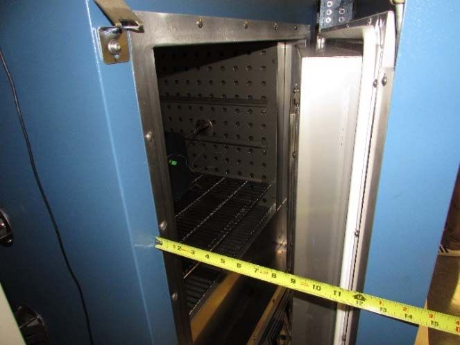
U.S. CONSUMER PRODUCT SAFETY COMMISSION

         DIRECTORATE FOR ENGINEERING SCIENCES

                      A PRELIMINARY ANALYSIS OF

            HYPERTHERMIA DEATHS ASSOCIATED
            WITH ELECTRIC ROOM/SPACE HEATERS

                                  MARCH 2019

                                   Arthur Lee
                              Electrical Engineer
                       Division of Electrical Engineering
                      Directorate for Engineering Sciences

The views expressed in this report are those of the CPSC staff and have not been
reviewed or approved by, and may not necessarily reflect the views of, the Commission.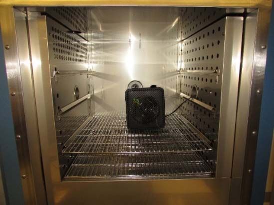
Abstract
        Electric space/room heaters can heat a specific room or space independently of other areas in
an occupancy. They can be used for or with a central heating system. The voluntary standard for
room heaters addresses the risk of ignition, but not the risk of overheated rooms. A room in which
a heater is located, depending on the room and the heater output, could sustain temperatures
exceeding 100° F (38° C). If an individual is exposed to above-normal core temperatures for an
extended period of time, the individual could experience hyperthermia and die.
        CPSC staff conducted a data search for heater-related deaths that occurred from January 1,
2008 to August 31, 2018. CPSC identified hyperthermia deaths that involved four children and one
adult caused from room heaters. Staff evaluated these incidents, conducted sample testing, and
reviewed voluntary standards. Staff’s review revealed that room heaters may present an
unaddressed hazard to consumers, especially to young children. Staff’s review further concluded
that children, people with disabilities, and senior citizens may be more susceptible to this hazard
because of their limited ability to take action or react to the elevated ambient temperature.
        According to staff’s preliminary analysis, certain steps could reduce the risk of
overheated rooms from room heaters. For example, educating consumers about the hidden hazard
and providing guidance on safely operating a room heater in a small room could help consumers
prevent room temperatures from rising above safe levels. In addition, staff suggests, standards
could be developed to address heater function. Manufacturers could incorporate sensors into
heaters sensors that will accurately monitor the room temperature to prevent room temperatures
from reaching an unsafe level.

 March 2019                                                                                       iii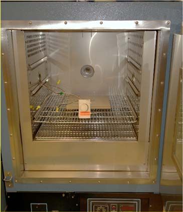
TABLE OF CONTENTS
Abstract.............................................................................................................................................. iii
1.0 INTRODUCTION ........................................................................................................................ 1
   1.1 Background ............................................................................................................................................. 1
   1.2 Objective ................................................................................................................................................. 1
2.0 INCIDENTS ................................................................................................................................. 1
   2.1 Review of Reported Incidents.................................................................................................................. 1
3.0 SPACE/ROOM HEATERS.......................................................................................................... 4
   3.1 Description of Space and Room Heaters ................................................................................................. 4
   3.2 Usage Location Information for Portable Heaters ....................................................................................... 4
4.0 TESTING OF ROOM/SPACE HEATERS .................................................................................. 5
   4.1 Small Portable Heater.............................................................................................................................. 5
   4.2 Control Thermostat for Built-in Wall Heater ........................................................................................ 13
5.0 VOLUNTARY STANDARDS FOR SPACE OR ROOM HEATERS (PORTABLE AND
FIXED) ............................................................................................................................................. 16
   5.1 Voluntary Standards for Room or Space Heaters.................................................................................. 17
   5.2 Voluntary Standard for Thermostats for Heaters .................................................................................. 17
6.0 DISCUSSION............................................................................................................................. 18
   6.1 Evaluating Changes to Start Temperature and Room Size on Heating Requirements .......................... 19
7.0 CONCLUSIONS ........................................................................................................................ 21
References ........................................................................................................................................ 22
Appendix .......................................................................................................................................... 23
   A. Summaries of the four incidents that did not appear to be related to a faulty or malfunctioning
   heating system ............................................................................................................................................. 23
   B.     Calculations for Section 6.0 Discussion .............................................................................................. 24
   C.     Table of R-factors used in the calculation for Section 6.0 Discussion ................................................ 25

                                                                 LIST OF FIGURES

 Figure 2.1. Number of hyperthermia deaths related to heaters ......................................................... 2
 Figure 3.1. Some of the types of room heaters ................................................................................. 4
 Figure 3.2. Where owners use portable electric heaters ................................................................... 5
 Figure 4.1 Components within the heater ......................................................................................... 6
 Figure 4.2. X-rays of the thermostat at MIN and MAX at room temperature .................................. 7
 Figure 4.3. Heater inside the conditioning oven ............................................................................... 8
 Figure 4.4. Air flow inside the conditioning oven (heater running, oven off) .................................. 9
 Figure 4.5. Thermocouple measurements during Test 2................................................................... 9
 March 2019                                                                                                                                                   vii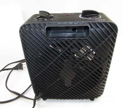
Figure 4.6. Oven chamber door partially opened about 9 inches (23 cm) ...................................... 10
Figure 4.7. Airflow with partially opened door .............................................................................. 10
Figure 4.8. Thermocouple measurements during Test 3................................................................. 11
Figure 4.9. Thermocouple measurements during Test 4................................................................. 13
Figure 4.10. Illustration of wiring for a built-in wall heater and thermostat .................................. 14
Figure 4.11. Thermostat in the conditioning oven .......................................................................... 14
Figure 4.12. Thermostat 1 conditioning oven results plot .............................................................. 15
Figure 4.13. Thermostat 2 conditioning oven results plot .............................................................. 16
Figure 6.1. Illustration of heat losses and gains in a room ............................................................. 18
Figure 6.2. Plot of heater requirement under certain conditions, such as room size ...................... 20

March 2019                                                                                                                 vii
1.0 INTRODUCTION
1.1 Background

        Most room or space heaters incorporate a regulating or control thermostat that allows
the user to set the desired temperature level for the heater to maintain. Room heaters allow a
specific room or space to be heated independently of other areas in an occupancy. They can be
portable or fixed-in-place heaters. Portable heaters are versatile and can be moved from one
room or space to another area that needs heating. In contrast, fixed heaters are permanent and
are intended for zone heating, rather than a central heating system, or to supplement heat in a
specific room.

        “Hyperthermia” is defined as a failure of the heat-regulating mechanisms of the body to
deal with the heat coming from the environment, which results in an abnormally high body
temperature.1 CPSC staff analyzed hyperthermia deaths associated with portable and fixed
room heaters. Staff not only reviewed the incidents, but also examined the voluntary standards
to understand the hazard scenarios associated with space heaters. This report summarizes
staff’s preliminary assessment.

1.2 Objective

       Staff’s objective in conducting this preliminary assessment was to consider potential actions
to reduce the hazards associated with hyperthermia deaths from consumer’s use of electric
room/space heaters.

                     2.0 INCIDENTS

2.1 Review of Reported Incidents

        The CPSC Injury and Potential Injury Incident (IPII) data system includes online reports,
consumer letters, CPSC Hotline complaints, newspaper clippings, and medical examiner
reports. CPSC field investigators may follow up on selected incidents after reviewing
collected death certificates, conducting In-Depth Investigations (IDIs) that may include
interviews with the victim, witnesses, and conferring with responding emergency personnel.
CPSC field investigators may also collect samples that they send to technical staff to evaluate.
These samples might be the actual products involved in the incident, or they may be
exemplars of the incident sample.

       CPSC staff searched the CPSC IPII database for all incidents related to
hyperthermia deaths and all types of heaters. The dates CPSC searched covered

1
 Hyperthermia: too hot for your health (June 27, 2012), National Institutes of Health. https://www.nih.gov/news‐
events/news‐releases/hyperthermia‐too‐hot‐your‐health‐1

March 2019                                                                                                    1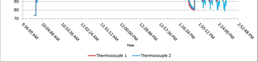
.
January 1, 2008 to August 31, 2018 2 The search revealed 15 deaths within the search
period. The incidents involved seven child deaths and eight older adult deaths, as
shown in Figure 2.1. The age range of the victims was less than 3 years of age to
more than 50 years of age.

                       Figure 2.1. Number of hyperthermia deaths related to heaters

Incidents Involving Adults Deaths

        Staff reviewed the eight adult deaths to determine whether the incidents
resulted in hyperthermia caused by heating products. The incidents all involved
heating systems, but not space or room heaters. Five of the eight deaths (4 of 7
incidents) appeared to be unrelated to a faulty or malfunctioning heating system, such
as a central furnace that sends heated air or water through the building using vents or
pipes and radiators. (See the appendix for summaries of these four incidents.)

Incidents Involving Children

        In reviewing the incident reports of the seven child deaths, staff sought to
determine whether the deaths were related to hyperthermia caused by heating systems
or space/room heaters. In one incident, which resulted in an asphyxiation, a room
heater was present, but was not the cause of the death. In a second incident, a
malfunctioning heating system was involved. Another incident contained a room
heater in the room that was reported the heater was off. The coroner determined the
death was caused by dehydration due to exogenous hyperthermia. The remaining four
incidents involved space or room heaters with hyperthermia reported as the cause of
death. The four space/room heater incidents involved victims with ages ranging from
12 months to 2 years old. For two of the incidents, there were IDI reports, but the
other two incidents only included information provided in medical examiner reports.
2 Product code search 310, 311, 318, 322, 384, 309, 312, 365, 388, 348, 391, 392, 393, 381, 340, 367, 399, 394, 119, 236, 118,

242, 133, and 134. NEISS Coding Manual, January 2017, U.S. Consumer Product Safety Commission. Retrieved on November 10,
2018 from cpsc.gov

March 2019                                                                                                                 2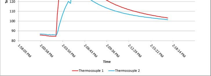
For the two incidents that did not include an IDI, the summaries, detailed below,
state that the children died from hyperthermia associated with the use of a room or
space heater:

       Database Narrative – “Decedent is a one year old male. Decedent placed
       to sleep by his father at 2200 hours on 4/14/09 in bedroom. Father turned
       on space heater in decedent’s bedroom because heater was not working
       and closed the bedroom door. Decedent was heard crying at 0300 hours
       on 4/15/09 by mother. Grandmother lives at residence and cares for
       child during the day. Grandmother went to check on decedent at 1300
       hours 4/15/09 and found him unresponsive and unplugged the space
       heater at that time. Upon our arrival, the temperature of the bedroom
       was 97 degrees F [36.1° C]. Upon arrival of paramedics, the decedent
       had a rectal temperature of 107 degrees F [41.7° C].” Cause of death:
       Exogenous hyperthermia.

       Database Narrative – “2 yr. old female left in bedroom with {deleted}
       heater that was allegedly set to fan. Found in morning unresponsive in
       bed suffering from acute hyperthermia (108F) [42.2° C]. Resuscitation
       [sic] was unsuccessful. Victim was pronounced DOA in the Emergency
       room. Firefighters find [sic] the heater heating the room severely. The
       bedroom window was however believed to have been closed also,
       perhaps for security reasons.” Cause of death: Exogenous hyperthermia.

      The three IDI reports provided additional details on the products and the
incident scenarios.

 Summary of an incident involving a 29-month-old female

        In 2017, a mother brought her 29-month-old daughter to her bedroom after her bath and
turned on the heater’s thermostat until the click sound was heard. The built-in wall heater
provided heat in the girl’s bedroom. The mother put her daughter in her crib for the night and left
a crack in the bedroom door. During the night, the mother heard her daughter crying and fussing
but did not check on her.

       The next morning, the father went to check on his daughter. When he entered the
bedroom, he found her unresponsive and called “9-1-1.” Fire and emergency personnel arrived
and noted that the child’s bedroom was extremely warm, and the heater was on. They turned off
the heater and opened a window in the room. The medics noticed her body was hot. The
coroner’s office ruled the cause of death from hyperthermia.

 Summary of an incident involving a 17-month-old female

      In 2018, a mother of a 17-month-old girl went to check on her daughter in late morning.
The mother discovered the girl unresponsive. When police and emergency medical services
(EMS) responders arrived on the scene, they immediately noticed how unusually warm the girl’s

March 2019                                                                                       3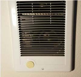
bedroom was, compared to the rest of the house. EMS turned off the heater that was on in the
room. Later, EMS personnel measured the temperature in the bedroom to be 95° F (35° C). The
coroner’s office ruled that the cause of death was consistent with hyperthermia.
3.0 SPACE/ROOM HEATERS
In five of the fatal incidents (4 children and 1 adult), the heat source that caused the
hyperthermia was a room or space heater that appeared to be functioning normally, but
apparently overheated a room. The remainder of this report focuses on room/space type heaters.
3.1 Description of Space and Room Heaters
Space or room heater designs can be portable or fixed in place. Portable heaters are
versatile and can be moved to heat different spaces within a structure. Fixed heaters are intended
for zone heating in place of a central heating system, or to provide supplemental heat for a specific
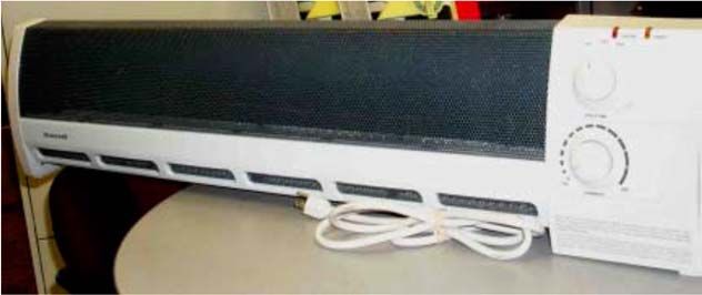
room. Baseboard heaters are unique because of their dimensional requirements. A “baseboard
heater,” by definition, must have the following dimensions: the length-to-height ratio of the heater
must be more than 2:1, and the depth of the heater must be less than 6 inches. Figure 3.1 shows
examples of three different types of room heaters.
Portable room heater Built‐in fixed room heater
Portable baseboard room heater
Figure 3.1. Some of the types of room heaters
3.2 Usage Location Information for Portable Heaters
March 2019 4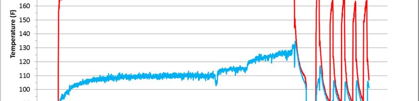
According to a Riedel Marketing Group study3 from 2013, 35 percent of respondents
indicated they use a portable heater mostly in children’s bedrooms, as shown in Figure 3.2.4 An
additional 21 percent of respondents indicated that they use a portable heater in the master
bedroom.
Graph reprinted with permission.
Figure 3.2. Where owners use portable electric heaters
4.0 TESTING OF ROOM/SPACE HEATERS
To understand how hyperthermia deaths occur as documented in the IDI reports, CPSC
staff examined and tested two types of room heaters collected from two incidents. One sample
collected was a small portable heater, and the other sample collected was a built-in wall heater
that uses a separate thermostat.
4.1 Small Portable Heater
The small portable heater from one incident did not show any signs of physical damage
or overheating, such as melting of the enclosure. There were two control knobs on top of the
heater. One knob controls the power and heat output (“OFF”, symbol for fan only, “○” white
circle for low heat, “ ” half-filled circle for medium heat, “●” black circle for high heat). The
other knob controls the regulating thermostat, marked “MIN” and “MAX,” with no temperature
indication between the words. A red light illuminates when the unit is plugged into an energized
receptacle. A tipover switch was located on the bottom of the heater. The entry for the
permanently attached power supply cord with a polarized plug was on the back of the heater. The
heater was listed to UL1278, Movable and Wall- or Ceiling- Hung Electric Room Heaters.
3
Riedel, A.J., (May 2013) 2013 U.S. Portable Heater Market Report, Riedel Marketing Company, Phoenix AZ
4
The survey sampling was 64 participants.
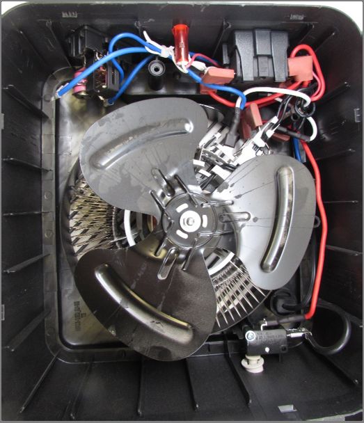
March 2019 5Figure 4.1 shows the various components of the heater with the rear enclosure removed.
Inside the unit are the regulating thermostat, temperature-limiting control (TLC) device, heater
output switch, heating element, tip-over micro switch, LED indicator light, and fan motor and
metal impeller.
On/off and heat
Regulating selection switch
thermostat
Thermal protector
temperature switch
device
Heating
element
Fan motor and
impeller Tip‐over micro
switch
Figure 4.1 Components within the heater
The regulating thermostat is the automatic temperature-setting control for the heater. The
TLC is the limiting control, which is located near the heating element and is intended to prevent
the unit from overheating. The TLC is a self-hold type, meaning that when it reaches its set
temperature, it will disconnect power from the heating element and fan motor until the user acts.
When the TLC contacts are open, a temperature-sensitive bimetal holds the contacts in an open
state until power is removed and sufficient time allows the TLC to cool and reset.
An x-ray of the regulating thermostat, as shown in Figure 4.2, illustrates the contacts
opened (set at MIN) and closed (set at MAX) when the knob is rotated from one end to the other
end of the dial. At about 1/3 of the turn from the MIN setting, the thermostat’s contacts could be
heard clicking on and off, depending on whether the knob was turned clockwise toward MAX, or
counterclockwise toward MIN. The lab room temperature was about 75° F (24° C).
March 2019 6Contacts open Contacts closed
Set at MIN Set at MAX
Figure 4.2. X-rays of the thermostat at MIN and MAX at room temperature
Because the incident involved a hyperthermia death, the testing focused on the ambient
temperatures relative to thermostat setting and TLC trip points. Staff conducted four tests inside
a conditioning oven to evaluate the response of the heater’s thermal devices. The tests were
designed to demonstrate various conditions that could occur around the heater for different
scenarios. The interior of the conditioning oven measures about 25 inches (64 cm) x 25 inches
(64 cm) x 25 inches (64 cm) or about 9 cubic-feet (0.25 m3). For Test 1, the oven’s heating
feature was used to generate heat within the oven and the heater sample was off during the test.
For Tests 2 through 4, the oven’s heating feature was not on for these tests. The heater was the
source of the ambient heating. Staff conducted the following four tests:
Test 1 – Heater off and conditioning oven temperature increased gradually. This test was to
evaluate the trip temperatures for the thermostats within the heater.
Test 2 – Heater energized at maximum settings in a closed, sealed space (conditioning oven
door closed and oven off). This test was to evaluate the heater’s heat output in tripping the
heater’s thermostats within a closed space.
Test 3 – Heater energized at maximum settings in a partially closed space (conditioning
oven door partially opened and oven off). This test was to evaluate the maximum
temperature of the air flowing into the heater without tripping the thermostat.
Test 4 – Test 3 repeated with a different thermostat dial setting (conditioning oven door
partially opened and oven off). This test was to evaluate the relationship between the
thermostat dial setting and temperature of the air flowing into the heater.
March 2019 7Test 1. Non-energized heater in the conditioning oven
The non-energized heater was placed within the conditioning oven, as shown in Figure
4.3. Two thermocouples were placed on the heater. Thermocouple 1 measured the air
temperature at the front of the heater, and Thermocouple 2 measured the air temperature at the
back of the heater. The continuity between the neutral and hot-plug terminals was monitored
with a digital multi-meter to determine when the regulating thermostat or the TLC activated, i.e.,
the meter indicated an open circuit.
Figure 4.3. Heater inside the conditioning oven
The regulating thermostat was set at maximum heat (MAX), and the heat setting was set
at the highest heat output (●), although any non-off setting is sufficient for this test because the
heater was not energized during this test. The oven door was closed. Starting at room
temperature 75° F (24° C), the oven temperature was increased about 1.8° F every 2 minutes.
The test was terminated when the oven temperature reached 122° F (50° C). Neither the
regulating thermostat, nor the TLC device activated during the test period.
Test 2 – Heater energized at maximum settings in a closed sealed conditioning oven chamber
After the previous test, the oven and heater self-cooled to almost room temperature
before staff started Test 2. The thermostat was set at maximum heat (MAX), and the heat setting
was on the highest heat output (●). After the oven door was closed, the heater was plugged into a
120 V receptacle. Thermocouple 1 measured the air temperature exiting the front of the heater,
and Thermocouple 2 measured the air temperature drawn into the heater, as illustrated in Figure
4.4.
March 2019 8Warm air
Chamber
Mixed chamber air is Thermocouple 2 Thermocouple 1
Heated air exits
drawn into the heater
the heater
Heater
Figure 4.4. Air flow inside the conditioning oven (heater running, oven off)
The temperatures on the heater rose quickly, as shown in Figure 4.5, because of the small
chamber volume. When the rear of the heater reached about 118° F (48° C), the TLC activated,
which de-energized the heater and caused the temperature to drop momentarily. After the heating
element shut off and the fan stopped rotating, there was no airflow passing over Thermocouple 2,
which caused the temperature to rise temporarily from residual heat from within the heater.
TLC activates
Heating due
to no airflow
Figure 4.5. Thermocouple measurements during Test 2
March 2019 9Test 3 – Heater energized at maximum settings in a partially closed conditioning oven
After the previous test, the oven and heater self-cooled to almost room temperature
before staff started Test 3. For this test, the chamber door was partially opened approximately 9
inches (23 cm), as shown in Figure 4.6. The partially opened oven door allowed some of the
heated air to exit and some of the cooler room air to enter the chamber, as illustrated in Figure
4.7. The thermostat was set at maximum heat (MAX) and the heat setting was on the highest heat
output (●). Thermocouple 1 measured the front of the heater or the airflow exiting the heater, and
Thermocouple 2 measured the rear of the heater, or the airflow entering the heater.
Figure 4.6. Oven chamber door partially opened about 9 inches (23 cm)
Cooler air
Mixed air
Heat loss
Mixed air
Cooler air
Figure 4.7. Airflow with partially opened door
The heater was plugged into a 120 V receptacle. The temperatures on the heater still rose
quickly. When the rear of the heater measured about 118.4° F (48° C), the TLC activated, which
de-energized the heater, as shown in Figure 4.8, from the start of the data through approximately
3:30 p.m., as shown in the graph. The heater was allowed to cool and the TLC was reset by
March 2019 10unplugging the heater, as shown in Figure 4.8, through approximately 3:40 p.m., as shown in the
graph below.
Airflow into heater maintained at about 110 F
Regulating thermostat switched to MAX
TLC activates Regulating thermostat activates Heater manually de‐energized
Figure 4.8. Thermocouple measurements during Test 3
The heater’s regulating thermostat knob was set halfway between the MIN and MAX. At
this setting, the regulating thermostat contacts were still closed. The heater was plugged into the
receptacle. Once the temperature on the back of the heater rose to about 93.2° F (34° C), the
regulating thermostat activated (opened) and de-energized the heater at approximately 3:43 p.m.,
as shown in the graph above.
The regulating thermostat was changed to MAX, which caused the heater to energize
from approximately 3:45 p.m. to the end of the test, as shown in the graph. To prevent the
chamber from heating too quickly, an external fan was placed on the floor outside the oven
chamber to remove additional heat from the chamber. This setup allowed the air that was
entering the back of the heater to maintain a constant temperature of about 110° F (43° C),
without causing the regulating thermostat or the TLC device to activate. The temperature stayed
at about 110° F (43° C) for 30 minutes, until the test was manually terminated.
Theoretically, this temperature state of 110° F (43° C), which represents the mixed room
air temperature being drawn into the heater, could be maintained for an extended period until
some environmental factor, such as a change in heat loss, altered the parameters.
March 2019 11Test 4 – Test 3 repeated (conditioning oven door partially opened)
As with the previous test, the oven and heater self-cooled to almost room temperature
before staff started Test 4. The same setup as Test 3 was performed with the chamber door
partially opened approximately 9 inches (23 cm), except the external fan was used at the
beginning of testing. The thermostat was set to maximum (MAX), and the heat setting was on
the highest heat output (●). Thermocouple 1 measured the front of the heater or the airflow
exiting the heater, and Thermocouple 2 measured the rear of the heater or the airflow entering
the heater.
Once the heater was energized, the temperature stabilized around 110° F (43° C) for
Thermocouple 2, as shown in Figure 4.9. Neither the regulating thermostat nor the TLC
activated after 2 hours. After about 2 hours into the testing, the oven chamber door was closed
until there was about a 5-inch (13-cm) opening. The temperature jumped up to around 118° F
(48° C) for Thermocouple 2, then gradually continued to increase until the temperature rose to
122° F (50° C), which caused the TLC device to activate, as shown in the graph below.
The heater was unplugged to reset the TLC, then the heater was re-energized. The
heater’s regulating thermostat knob was set in the middle, between the MIN and MAX settings,
which caused the heater’s regulating thermostat to switch off and back on when the airflow at the
back of the heater measured around 108° F (42° C) and 90° F (32° C).
March 2019 12TLC activates
Open door closed to 5 inches
Regulating thermostat set
between Min and Max
TLC reset
Figure 4.9. Thermocouple measurements during Test 4
4.2 Control Thermostat for Built-in Wall Heater
The sample used for testing was a built-in wall heater (fan/heater) that uses a separate
control thermostat typically mounted on a wall. The thermostat is wired in series with one of the
conductors for the heater, as illustrated in Figure 4.10. The heater unit relies on the external
thermostat for regulating its output. The thermostat is a thermal-mechanical type, which uses a
bi-metal element to control the switch contacts. The thermostat dial contains numbers and
markings that would suggest the units are in degrees Fahrenheit, even though the units were not
labeled on the dial.
March 2019 13Mounted thermostat
Thermostat
wire
Heater
Supply wire wires
Supply wire
240 VAC
Buit-in wall heater
Figure 4.10. Illustration of wiring for a built-in wall heater and thermostat
Two thermostats were tested individually, by placing each thermostat in a conditioning
oven, as shown in Figure 4.11, and controlling the same heater outside the conditioning oven.
The thermostat was mounted inside a single-gang plastic electrical box. Five thermocouples
measured the temperature inside the oven. Four of the five thermocouples were placed inside the
electrical box and one thermocouple outside the electrical box. The conditioning oven’s
temperature was programmed to increase 1.8°F every 2 minutes.
Figure 4.11. Thermostat in the conditioning oven
March 2019 14Thermostat 1 Testing
Even before the test started, turning the temperature setting dial from its minimum setting
produced an “off” click below 50 on the thermostat dial. This revealed that the set/operating
point was not accurate because the lab room temperature was not below 50° F (10° C). Ideally,
when the thermostat’s dial is turned slightly above 70, a clicking (contacts closing and opening)
sound should be heard because the room temperature was 72° F (22° C).
For the testing, the dial was set at each of the display marks 50, 55, 60, 70, 80, and 90.
When the thermostat dial was set at 50, the thermostat opened when the oven temperature
reached 91° F (33° C). When the thermostat dial was set at 90, the thermostat did not open until
the oven temperature reached 177° F (81° C). The test results graphed in Figure 4.12 show the
actual thermostat response was consistently higher than the ideal response of the thermostat. On
average, the thermostat activated and de-energized the heater at about 60° F (16° C), higher than
the dial setting.
Actual
Thermostat
Response
Ideal
Thermostat
Response
Figure 4.12. Thermostat 1 conditioning oven results plot
Thermostat 2 Testing
Turning the temperature setting dial before starting the testing revealed that the
setting/operating point differences were off, but not as far as for Thermostat 1. The switch
clicking could be heard between 80 and 85 mark on the dial display, and the room temperature
was about 72° F (22° C). For this testing, the dial could only be set at around the 83, 85, and 90
mark because the thermostat would only begin to turn on above 80 on the dial. When the
thermostat dial was set at around 83, the thermostat opened when the conditioning oven
March 2019 15temperature reached 94° F (34° C). When the thermostat dial was set at 90, the thermostat did
not open until the conditioning oven temperature reached 109° F (43° C). The graphing of the
test results in Figure 4.13 shows the actual thermostat response was higher than the ideal
response of the thermostat, but the shift was not as pronounced as Thermostat 1. On average, the
thermostat activated and de-energized the heater about 14° F higher than the dial setting.
.
Actual
Thermostat
Response
Ideal
Thermostat
Response
Figure 4.13. Thermostat 2 conditioning oven results plot
In both of the thermostats tested, the calibration of the thermostats appeared to be shifted
higher than the dial display. The inaccurate calibration of the thermostats could result in the
room achieving a higher temperature than what the occupant may have intended, if the occupant
was relying on the thermostat’s dial display as the set-desired room temperature. For Thermostat
1, if the dial is set at the 55 mark or above, the heater would operate until the room temperature
is 100° F (37.8° C) or greater. For Thermostat 2, if the dial is set around 86 or above, the heater
would operate until the room temperature is 100° F (37.8° C) or greater.
5.0 VOLUNTARY STANDARDS FOR SPACE OR
ROOM HEATERS (PORTABLE AND FIXED)
The voluntary standard for portable heaters is Underwriters Laboratories (UL) 1278
Movable and Wall- or Ceiling-Hung Electric Room Heaters, Edition 4. The scope of this
standard covers movable and wall- or ceiling-hung electric room-heating equipment rated 600
volts or less to be used in ordinary locations in accordance with the National Electrical Code,
ANSI/NFPA 70 (NEC).
The voluntary standard for fixed heaters is UL 2021 Fixed and Location-Dedicated
March 2019 16Electric Room Heaters, Edition 4. The scope of this standard covers fixed and location-
dedicated electric room heating equipment rated 600 volts or less to be used in ordinary
locations in accordance with the NEC.
The voluntary standard for baseboard heaters is UL 1042 Electric Baseboard Heating
Equipment, Edition 5. The scope of this standard covers portable and fixed electric baseboard
heating equipment rated at 600 volts or less, to be used in ordinary locations in accordance with
the NEC.
UL 873 Temperature-Indicating and -Regulating Equipment, Edition 12 applies to
thermostats built in or external to the heating appliance’s electrical equipment for control of
heating appliances rated 600 volts or less, to be used in ordinary locations in accordance with
the NEC. The standard covers general-use equipment for field-installation and controls
intended to be factory installed on or in certain appliances as safety, limiting, or operating
controls. These controls respond directly or indirectly to changes in temperature, humidity, or
pressure to control the equipment or appliance’s operation.
The construction and performance requirements in UL 1278, UL 2021 and UL 1042
address the risks of electric shock and fire. Addressing fire risk is understandable because heaters
are one of the leading appliances known to cause household fires. The CPSC staff report, 2013-
2015 Residential Fire Loss Estimates, indicates that portable and fixed (non-central) heaters
accounted for an annual average of 4,500 structure fires from 2013 to 2015.5
5.1 Voluntary Standards for Room or Space Heaters
The normal operation performance tests in UL 1278, UL 2021, and UL 1042 limit the
maximum temperature to 117 degrees F (47.2° C) for surfaces adjacent to the heater, which is
intended to prevent nearby combustibles from igniting.6 The standards specify that the
“temperature-regulating thermostat is one that functions only to regulate the temperature of the
heater under intended conditions of use, and whose malfunction would not result in risk of
fire.” The standard does not address excessive temperatures within the space that would pose a
risk of hyperthermia to an occupant. The standard specifies further that a safety control or a
temperature-limiting control (one designed to prevent unsafe operation of a heater) shall
interrupt power (to a sufficient number of heating elements) to reduce temperature as not to
exceed 347° F, obviously intended to prevent the risk of fire.
5.2 Voluntary Standard for Thermostats for Heaters
UL 873, Temperature-Indicating and -Regulating Equipment, Edition 12, applies to
thermostats separate from or integral to a heater. Residential Operating Controls, such as
room thermostats, are subjected to performance testing to ensure that operation does not pose
a risk of fire or cause damage to any materials used in the equipment. The standard does not
5
Miller, D. (July 2018) 2013‐2015 Residential Fire Estimates, U.S. National Estimates of Fires, Deaths, Injuries, and Property
Losses from Unintentional Fires; U.S. Consumer Product Safety Commission, Bethesda, MD
6 UL 1042 Electric Baseboard Heating Equipment, UL 1278 Movable and Wall‐ or Ceiling‐Hung Electric Room Heaters, UL 2021
Fixed and Location‐Dedicated Electric Heaters, Underwriters Laboratories, Northbrook, IL
March 2019 17address evaluating the temperature-indicating or -regulating equipment allowing excessive
temperatures that would pose a risk of hyperthermia to the occupant within a space. The
standard does not require calibration verification for heater thermostats, but it does have
calibration verification for water-heaters and electric range-controls.
6.0 DISCUSSION
Heat can enter the room from a room heater through convection. The room and the air
within the room absorb the heat, but heat is also lost by conduction through the walls,
windows, doors, floor, and ceiling. As the heat is lost in the room, there is a demand from the
heater to produce heat to reach the set temperature. There may be parameters where the heat
lost in the room, room volume, and heater output allow the room temperature to be maintained
at a stabilized temperature that is below the set point of the heater’s thermostat, but is high
enough to pose a risk to some occupants, if exposed for an extended period of time,
particularly for occupants whose age or disabilities might limit their ability to respond to the
elevated temperature.
In the incidents, a space/room heater appeared to elevate the temperatures within the
room to a level that was fatal for a toddler. Staff evaluated the conditions that would be
required to elevate the room temperature to such a level. The simplified illustration shown in
Figure 6.1 indicates that the room temperature is determined by the amount of heat gain, minus
heat loss. By considering various room sizes and starting temperatures, but keeping all other
parameters the same, it is possible to illustrate that a typical room heater output may raise
room temperatures to 100° F. This section examines the main variables, such as heat losses,
starting temperature, and room size, to determine the room heater needed to raise the
temperature to 100° F.
Heat loss
Airflow is for
illustration purposes only
Heat loss
Heat loss
Heat source
Portable heater
Heat source
Floor supply register
Heating
Heat loss system
Figure 6.1. Illustration of heat losses and gains in a room
March 2019 186.1 Evaluating Changes to Start Temperature and Room Size on Heating Requirements
The calculations were based on using variables from a hyperthermia incident in which
some of the information for room size, room layout, and room construction were known. For
the unknowns, industry construction standards were used.
Heat losses, which have a specific R-Value, occur through the walls, ceiling, floor,
windows, and door. R-values are used in describing effectiveness of insulation and in analysis
of heat flow across assemblies (such as walls, roofs, and windows) under steady-state
conditions. If given the R-Value, area affected, and temperature difference, the amount of heat
loss in an hour can be calculated by the equation:
To evaluate the impact of room sizes on the heating requirement, the analysis will use
three different room sizes. The first bedroom size is the minimum bedroom, as required by the
International Residential Code (IRC), and that would be defined as “habitable.” The IRC
specifies the minimum bedroom must be have a minimum floor area of 70 square-feet with a
minimum of 7 foot ceilings, which equates to 490 cubic feet.7 The second bedroom size is an
incident bedroom, which is 10 feet x 10 feet with 8 foot ceilings and equates to about 800 cubic
feet. The third bedroom for the analysis is a bedroom that is 1 foot larger in length and width
than the second bedroom. The room’s dimensions are 11 feet x 11 feet with 8 foot ceilings and
equates to 968 cubic feet. All other parameters, such as the number and type of windows,
number and type of interior door, and wall, floor, and ceiling construction stayed fixed for each
room size.
In addition to the room size changing in the calculations, another key variable that
determines the heating requirement is the starting temperature, which can be the outside
temperature or HVAC set temperature. Because the analysis calculated the heater watts needed
to raise the room temperature to 100° F, the starting temperature would be a factor in the
heater output. For example, if the outside temperature was very cold, the delta between the
starting temperature and 100° F would be greater than if the outside temperature was not as
cold. A sample calculation is located in the appendix that was used for the analysis. The plots
shown in Figure 6.2 demonstrate that, depending on room size and starting temperature, a
1,500 watt heater is capable of elevating the room temperature to 100° F. For example, a
1,500-watt heater can raise the room temperature of an 800 cubic-feet room from 61° F (16° C)
to 100° F (38° C) or a 968 cubic-feet room from 65° F (18° C) to 100° F (38° C).
7 2018 International Residential Code for One‐ and Two‐Family Dwellings, International Code Council (ICC).
March 2019 191,500 watt heater achieving 100° F
starting at 65° F room temperature
1,500 watt heater achieving 100° F
starting at 62° F room temperature
Figure 6.2. Plot of heater requirement under certain conditions, such as room size
March 2019 207.0 CONCLUSIONS
Space and room heaters are designed to produce heat without becoming fire and
shock hazards. The voluntary standards aim to achieve this objective. However the
voluntary standards does not address the potential for a room or space heater to overheat in an
occupied space. The heater has the potential to sustain elevated room temperatures, above
safe long-term exposure levels (but below the risk of fire), which may pose a risk of
hyperthermia to occupants, especially to young children, people with disabilities and senior
citizens. A preliminary analysis of incidents, sample testing, and voluntary standards for
room heaters indicates that these types of heaters may present an unaddressed hazard to a
certain segment of vulnerable consumers, such as children and the elderly.
Hazard
Space or room heaters, which can be portable or fixed-in-place, can elevate the room
temperature to levels that may be dangerous for some occupants.
Small children, people with disabilities, and senior citizens may be more vulnerable in
an overheated room because of their limited ability to take action.
Voluntary Standard
The voluntary standards for portable, fixed, and baseboard heaters do not
address scenarios in which room heaters may elevate the occupied space at a
temperature that may not be safe for long-term exposure.
The voluntary standard for thermostats used in or with heaters do not address the
accuracy of thermostat displayed markings.
Staff’s preliminary analysis suggests steps that could reduce the risk of overheated
rooms from room and space heaters.
Educating consumers about the hidden hazard, and providing guidance on safely
operating a room heater in small rooms, could allow consumers to prevent room
temperatures from rising above safe levels.
Calibrating thermostats to function at the displayed setting, and incorporating the use
of only numeric displays that correspond to temperature, will reduce tolerances and
improve accuracy, thus reducing the ambiguity in the intended heat output. The lack
of tolerances and accuracy may lead to higher than expected temperatures.
Evaluating revisions of the voluntary standards to include provisions addressing heater
function, such as heaters incorporating sensors that accurately monitor the room
temperature to prevent the room temperature from reaching an unsafe level, may
prevent unexpected overheating of a room and/or incorporating warning and safety
language to inform consumers of the possible hazard.
March 2019 21References Air Change Rates in typical Rooms and Buildings, Retrieved November 23, 2018, from engineeringtoolbox.com ASHRAE Standard Ventilation for Acceptable Indoor Air Quality, Addendum to 62-2001 Ventilation Rate Procedure (June 2003), American Society of Heating, Refrigerating, and Air- Conditioning Engineers, Inc., Atlanta, GA Miller, D., (July 2018), 2015 Residential Fire Loss Estimates, U.S. National Estimates of Fires, Deaths, Injuries, and Property Losses from Unintentional Fires, US Consumer Product Safety Commission, Bethesda, Maryland. Retrieved from cpsc.gov. National Institutes of Health. (June 27, 2012). Hyperthermia: too hot for your health. Retrieved October 23, 2018, from https://www.nih.gov/news-events/news-releases/hyperthermia-too- hot-your-health-1 R-Value Table, Insulation Values for Selected Materials. Retrieved October 22, 2018, from Coloradoenergy.org R-Value Table, Common Building Materials, Retrieved October 22, 2018, from www.coloradoenergy.org/procorner/stuff/r-values.htm Riedel, A.J., (May 2013). 2013 U.S. Portable Heater Market Report, Riedel Marketing Company, Phoenix AZ. Room Heating Calculator, Chromalox, Retrieved October 22, 2018, from http://www.chromalox.com/resources-and-support/calculators/comfort-heater Selecting a Home Heating System, GreenRiverSide, Retrieved November 1, 2018, from https://www.energydepot.com UL 873 Temperature-Indicating and -Regulating Equipment, Underwriters Laboratories Headquarters, Northbrook, IL UL 1042 Electric Baseboard Heating Equipment, Underwriters Laboratories Headquarters, Northbrook, IL UL 1278 Movable and Wall- or Ceiling-Hung Electric Room Heaters, Underwriters Laboratories Headquarters, Northbrook, IL UL 2021 Fixed and Location-Dedicated Electric Room Heaters, Underwriters Laboratories Headquarters, Northbrook, IL U.S. Consumer Product Safety Commission. (January 2017). NEISS Coding Manual. Bethesda, Maryland. https://www.cpsc.gov/s3fs- public/2017NEISSCodingManualCPSConlyNontrauma.pdf March 2019 22
Appendix
A. Summaries of the four incidents that did not appear to be related to a faulty or
malfunctioning heating system
A 76-year-old adult’s home air conditioning had stopped working, and the
July temperatures in Texas raised the indoor temperature to almost 100° F
(37.8° C) for an extended period of time. This incident was not related to
a heater as the cause of hyperthermia death.
A gas heater was used indoors and produced carbon monoxide and
elevated temperatures. The 76-year-old male was physically and mentally
challenged, which may have contributed to the circumstances for the
death. The cause of death was ruled as carbon monoxide poisoning and
hyperthermia.
An 84-year-old male was discovered unresponsive in his home. The cause
of death was reported as hyperthermia from high ambient temperatures.
The victim had a history of using a gas furnace and an electric portable
heater at the same time. The temperature inside the home was reported as
being over 100° F (37.8° C) and his body temperature was about 105° F
(40.6° C) an hour after the discovery.
A normally operating heating system resulted in two deaths. The report
states the deaths of a 74-year-old female and her 60-year-old brother were
most likely caused by hyperthermia due to high ambient temperatures. The
home was reported as being in disrepair with large holes in the roof. The
thermostat for the home’s heating system was located in a poorly insulated
room, which caused the furnace to operate nonstop. The two victims were
discovered in another part of the home with ambient temperatures over
100° F (37.8° C).
Faulty or malfunctioning heating systems reportedly caused three adult deaths
(3 incidents). Two of the incidents occurred in the winter, and one occurred in the
summer. These three incidents are summarized below:
A 90-year-old female was discovered unresponsive in her home. The
temperature inside the home was reportedly 113° F (45° C). The relay
switch for the heating system was faulty.
A 51-year-old female was discovered unresponsive. The cause of death
was hyperthermia from a malfunctioning heating system. The victim was
physically immobile due to lower back and knee surgeries.
An 83-year-old male was discovered unresponsive in his home in July.
The temperature in the home exceeded 110° F (43° C). The heating,
ventilation, and air conditioning (HVAC) system was set to cool, but was
producing heat from the vents. The report states that the home’s heating
and cooling system was recently repaired before the incident. The male
died from complications of hyperthermia.
March 2019 23B. Calculations for Section 6.0 Discussion
The window and door sizes and construction for the room in one of the incidents are
unknown, staff used standard door sizes and windows to determine the R-values. The standard
door selected for the calculations was a wood hollow-core (1-3/4”) interior door. The standard
windows for the calculations were double insulating glass with a ½” air space between the panes.
Because the IDI report noted that the space under the flooring did not have any insulation, staff
selected standard flooring construction. The R-factor for the flooring was for conventional wood
joist floors with ¾” plywood subfloor covered with carpet and pad over an unheated and
ventilated crawl space. Staff assumed that the interior walls are conventional wood stud walls
with interior sheetrock construction. The exterior walls selected for the R-factor are conventional
wood stud walls with interior sheetrock and stucco exterior. Since two of the four walls are
interior walls and the other two are exterior walls, the calculated R-value is an average of the two
types of walls. The selected R-factors for the different items of the room are listed below. The
calculated total transmission loss is 107.7 BTU/hr/Degrees F.
Transmission Losses Calculation
Item Area R-Factor =BTU/hr/Degrees F
Windows 30 Sq.ft. /2.04 =14.7
Doors 16.5 Sq.ft. /2.17 =7.6
Net Walls 320 Sq.ft. /5.31 =60.3
Ceiling 100 Sq.ft. /51.17 =2.0
Floor 100 Sq.ft. /4.32 =23.1
Transmission Losses Total =107.7
To find the heat output of just the portable heater requires calculating first the heat output
of the floor supply register to raise the temperature to what the whole home thermostat is set at
and then calculating the heat output of the portable heater to raise the room temperature to
100°F.
The calculation for the room heater output to achieve 100°F from 71°F, which is the
estimated setting by the central heating system, is shown below. The air change rate per hour for
a residential is between 1 and 2 ACH.8 Staff selected 1.5 as the ACH, which is the middle of the
range. The environmental conditions are listed below.
Environmental Conditions
Air Changes per hour (ACH) = 1.5
Initial Temperature =71° F
8
Air Change Rates in typical Rooms and Buildings, Retrieved November 23, 2018, from engineeringtoolbox.com
March 2019 24Inside Temperature =100° F
Temperature Difference =29° F
The total losses were calculated to be 113 Cu Ft/Hr. The calculations are shown below,
Total Heating Requirement Calculation
Room Cu. Footage x Air Changes per hour = Cu.ft/hr
800 ft. x 1.5 =1200
Calculated Total Losses
Air Changes Loss: 1200 Cu.ft/hr. x 0.019 BTU/Cu.ft =22.8
Transmission Loss Total: =107.7
Total Losses =130.5
The total heating requirement to achieve a 100°F room with an initial temperature of
71°F was calculated using the total losses and temperature difference of 29°F. The total BTU/hr
needed by just the room heater would be 3,784.5 BTU/hr and this converts to a heater output at
1,108.2 Watts. The heating requirement calculations for just a room heater is shown below:
Total Heating Requirement Calculation
Total Losses x Temperature Differences =Total BTU/hr
130.5 x29° F =3,784.5 BTU/hr
Conversion to Watts
BTU/hr. per Watt /3.412
Total Watts (Total BTU/hr/BTU/hr per Watt) = 1,108.2
C. Table of R-factors used in the calculation for Section 6.0 Discussion
oF
Item ft2 h/BTU
Windows:
Double insulating glass (1/2" air space) 2.04
Doors:
Wood Hollow Core Flush (1 3/4") 2.17
Ceiling:
Attic air film 0.61
Sheathing 0.5
Fiberglass Batt (12 inches) 49
Sheetrock 0.45
Inside air film 0.61
Total R value 51.17
Exterior Walls:
Outside air film 0.25
Sheathing 0.5
March 2019 25oF
Item ft2 h/BTU
Inside air cavity 0.94
Sheetrock 0.45
Inside air film 0.68
StuccoYou can also read