MetroCluster IP Solution Architecture and Design
←
→
Page content transcription
If your browser does not render page correctly, please read the page content below
Technical Report

 MetroCluster IP
 Solution Architecture and Design
 Cheryl George, NetApp
 Nov 2020 | TR-4689

Abstract
NetApp® MetroCluster is a continuously available storage solution for NetApp ONTAP®
running on FAS and AFF systems. MetroCluster IP is the latest evolution that uses an
Ethernet-based back-end storage fabric. MetroCluster IP provides a highly redundant
configuration to meet the needs of the most critical business applications. Because
MetroCluster IP is included in ONTAP, it does not require a separate license, and it provides
NAS and SAN connectivity for clients and servers that use ONTAP storage.
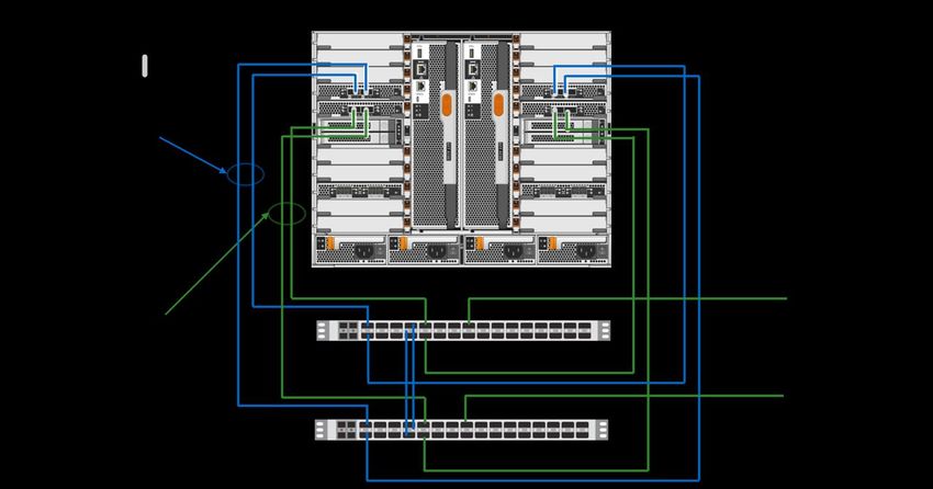
TABLE OF CONTENTS

MetroCluster Overview .......................................................................................................................... 5
     Continuous Availability Solution Overview.......................................................................................................... 5
     MetroCluster IP Compared to MetroCluster FC .................................................................................................. 6

MetroCluster IP Architecture ................................................................................................................ 6
     Disaster Recovery Group .................................................................................................................................. 8
     Replication in MetroCluster IP ........................................................................................................................... 8
     Network.......................................................................................................................................................... 10
     Storage .......................................................................................................................................................... 12

Solution Design ................................................................................................................................... 13
     Confirming Support ......................................................................................................................................... 13
     Sizing a Solution ............................................................................................................................................. 13
     Hardware Components ................................................................................................................................... 15
     MetroCluster IP Switches ................................................................................................................................ 15
     Network Adapters ........................................................................................................................................... 17
     Network Configuration..................................................................................................................................... 17
     AFF A700 and FAS9000 MetroCluster IP Node to Switch Connections ............................................................. 19
     AFF A250, AFF A300, FAS500f, and FAS8200 MetroCluster IP Node to Switch Connections ........................... 21
     AFF A220 and FAS2750 MetroCluster IP Node to Switch Connections ............................................................. 22
     AFF A400, FAS8300, and FAS8700 MetroCluster IP Node to Switch Connections ............................................ 22
     Cluster Fabric ISL ........................................................................................................................................... 23
     MetroCluster IP ISL Link Design ...................................................................................................................... 23
     Shared Layer 2 MetroCluster IP ISL ................................................................................................................ 27
     Using Compliant Switches – MetroCluster IP with Existing Switches................................................................. 28
     Active-Passive Configurations ......................................................................................................................... 28

Operation and Administration............................................................................................................. 29
     Switchover and Takeover ................................................................................................................................ 29
     ONTAP Mediator Software .............................................................................................................................. 30
     Tiebreaker Software........................................................................................................................................ 31

Interoperability .................................................................................................................................... 33
     SnapMirror ..................................................................................................................................................... 33
     NetApp ONTAP FlexGroup Volumes ............................................................................................................... 33
     NetApp FlexCache.......................................................................................................................................... 33
     NetApp FabricPool.......................................................................................................................................... 34

 2          MetroCluster IP Solution Architecture and Design                                                              © 2020 NetApp, Inc. All rights reserved.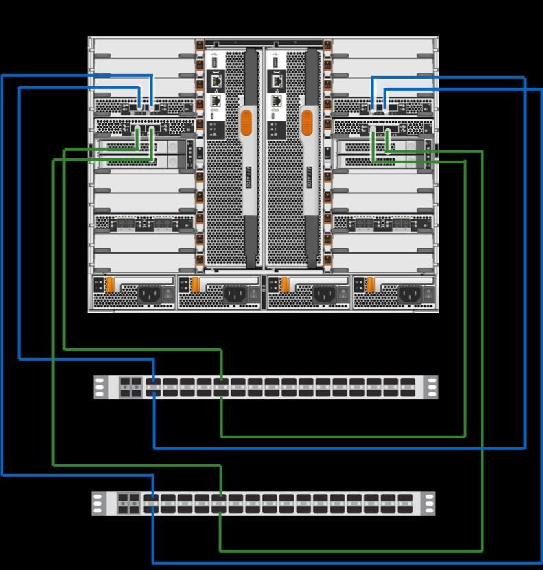
SVM Mirror and SVM Disaster Recovery ......................................................................................................... 34

Where to Find Additional Information ................................................................................................ 34

Version History .................................................................................................................................... 35

LIST OF TABLES
Table 1) MetroCluster IP switch models. ................................................................................................................ 15
Table 2) Supported copper cables for AFF A700. ................................................................................................... 20
Table 3) AFF A700 MetroCluster IP and cluster interconnect node to switch cables. ................................................ 20
Table 4) OM4 fiber optic cables.............................................................................................................................. 21
Table 5) AFF A300 cluster interconnect node to switch cables. ............................................................................... 22
Table 6) AFF A300 MetroCluster IP network node to switch cables. ........................................................................ 22
Table 7) ISL maximum characteristics. ................................................................................................................... 23
Table 8) 40Gb 3m to 5m distance between switches (approximate cable length). .................................................... 24
Table 9) 100Gb 3m to 5m distance between switches (approximate cable length). .................................................. 24
Table 10) Short-range optical module for 40GbE switch. ......................................................................................... 24
Table 11) Short-range optical module for 100GbE switch. ....................................................................................... 24
Table 12) 40Gb and 100Gb optical cables. ............................................................................................................. 24

LIST OF FIGURES
Figure 1) MetroCluster IP and VMware vSphere Metro Storage Cluster. .................................................................... 6
Figure 2) MetroCluster IP architecture. ..................................................................................................................... 7
Figure 3) Storage and server ................................................................................................................................... 7
Figure 4) MetroCluster HA and disaster recovery...................................................................................................... 8
Figure 5) Mirroring write data blocks....................................................................................................................... 10
Figure 6) MetroCluster IP combined fabric. ............................................................................................................. 11
Figure 7) Hardware Universe platform limits. .......................................................................................................... 15
Figure 8) AFF A700 one site network example. ...................................................................................................... 16
Figure 9) AFF A300 one site network example. ...................................................................................................... 16
Figure 10) AFF A220 one-site network. .................................................................................................................. 17
Figure 11) RCF File Generator............................................................................................................................... 18
Figure 12) MetroCluster IP 100Gb switch port assignments. ................................................................................... 19
Figure 13) MetroCluster IP 40Gb switch port assignments. ..................................................................................... 19
Figure 14) MetroCluster IP 10/25Gb switch port assignments. ................................................................................ 19
Figure 15) AFF A700 node to switch network connections. ..................................................................................... 20
Figure 16) Optical connection. ............................................................................................................................... 21
Figure 17) AFF A300 node to switch network connections. ..................................................................................... 22
Figure 18) Site A passive DWDM example using 10Gb optical modules and QSA. .................................................. 26
Figure 19) ISL with 10Gb port adapter. ................................................................................................................... 27

 3          MetroCluster IP Solution Architecture and Design                                                         © 2020 NetApp, Inc. All rights reserved.
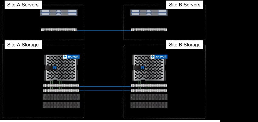
Figure 20) AFF A700 single site without network switch example. ........................................................................... 28
Figure 21) Active-passive cluster or site. ................................................................................................................ 29
Figure 22) Active-passive HA. ................................................................................................................................ 29
Figure 23) MetroCluster Mediator site. ................................................................................................................... 31
Figure 24) MetroCluster Tiebreaker site. ................................................................................................................ 32
Figure 25) Tiebreaker site link failure...................................................................................................................... 32
Figure 26) Tiebreaker site failure............................................................................................................................ 33
Figure 27) SVM disaster recovery. ......................................................................................................................... 34

 4          MetroCluster IP Solution Architecture and Design                                                        © 2020 NetApp, Inc. All rights reserved.
MetroCluster Overview
NetApp MetroCluster configurations are used by thousands of enterprises worldwide for high availability
(HA), zero data loss, and nondisruptive operations both within and beyond the data center. MetroCluster
is a free feature of ONTAP software that synchronously mirrors data and configuration between two
ONTAP clusters in separate locations or failure domains.
MetroCluster provides continuously available storage for applications by automatically managing two
objectives:
• Zero recovery point objective (RPO) by synchronously mirroring data written to the cluster
• Near zero recovery time objective (RTO) by mirroring configuration and automating access to data at
the second site
MetroCluster provides simplicity with automatic mirroring of data and configuration between the two
independent clusters located in the two sites. As storage is provisioned within one cluster, it is
automatically mirrored to the second cluster at the second site. NetApp SyncMirror® provides a complete
copy of all data with a zero RPO. This means that workloads from one site could switch over at any time
to the opposite site and continue serving data without data loss.
MetroCluster manages the switchover process of providing access to NAS and SAN-provisioned data at
the second site. The design of MetroCluster as a validated solution contains sizing and configuration that
enables a switchover to be performed within the protocol timeout periods or sooner (typically less than
120 seconds). This results in a near zero RPO with the recovery for storage occurring within the storage
protocol timeout periods. Applications can continue accessing data without incurring failures.
MetroCluster is available in several variations defined by the back-end storage fabric. There are two main
types of storage fabric for MetroCluster: FC and Ethernet. The Ethernet storage fabric is referred to as
MetroCluster IP.
MetroCluster IP was introduced in ONTAP 9.3. With the evolution of Ethernet storage and the adoption of
high-performance Ethernet, MetroCluster IP offers a compelling solution for continuously available
storage with a lower component count, lower cost, and increased functionality.
Continuous Availability Solution Overview
MetroCluster fulfills the need for continuously available storage. When combined with similar application
availability products, the complete solution provides a highly resilient architecture that can continue
operating even in the event of a site-wide disaster.
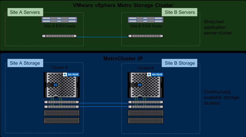
One example is using MetroCluster IP with VMware vSphere Metro Storage Cluster (vMSC). Combining
the two products creates a highly resilient virtualized infrastructure that addresses the needs of business-
critical applications. MetroCluster IP provides storage availability and vMSC provides a cross-site
compute cluster that is available to operate even in the event of a complete site outage.
5 MetroCluster IP Solution Architecture and Design © 2020 NetApp, Inc. All rights reserved.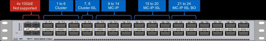
Figure 1) MetroCluster IP and VMware vSphere Metro Storage Cluster.

Similar multisite application solutions are available for databases and other applications that work well
with MetroCluster.

MetroCluster IP Compared to MetroCluster FC
The following features outline the differences between MetroCluster IP and FC:
•       MetroCluster IP uses an Ethernet back-end storage fabric rather than an FC back-end storage fabric,
        eliminating the need for dedicated FC switches.
•       MetroCluster IP collapses the intercluster switches for both local and remote replication, eliminating
        the need for FC switches.
•       MetroCluster IP does not require SAS bridges.
•       MetroCluster IP replicates NVRAM with iWARP by using the same back-end Ethernet ports as the
        storage network.
•       MetroCluster IP accesses remote disks using iSCSI protocol with the remote disaster recovery node
        acting as the iSCSI target, supporting flash systems with integrated storage.
MetroCluster FC has been shipping because ONTAP 8.3 and is based on an FC storage fabric.
MetroCluster FC is also available in a smaller configuration called MetroCluster Stretch FC. For more
information about MetroCluster FC with ONTAP, see TR-4375: NetApp MetroCluster FC for ONTAP.

MetroCluster IP Architecture
MetroCluster IP uses an Ethernet storage fabric. The MetroCluster storage fabric, also referred to as the
back-end storage fabric, is used solely by ONTAP. It is a separate dedicated network for ONTAP cluster
interconnect, MetroCluster SyncMirror, and MetroCluster NVRAM mirror communications.

    6       MetroCluster IP Solution Architecture and Design                     © 2020 NetApp, Inc. All rights reserved.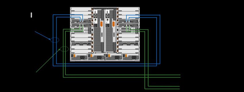
Figure 2) MetroCluster IP architecture.

MetroCluster IP hardware summary:
•       One HA pair controller per site
•       Two high-speed Ethernet switches per site:
        − Collapsed intracluster and intercluster switches for local and remote replication
•       Disk shelves or internal storage
MetroCluster extends the availability of ONTAP by mirroring data between two independent ONTAP
clusters. Each cluster is in a site or failure domain and leverages the standard HA features on the FAS or
AFF systems. MetroCluster provides the capability to mirror both data and configuration between the two
ONTAP clusters. MetroCluster includes validated system parameters and limits designed to provide
failover from one site to the other within standard timeout periods for storage protocols.
MetroCluster features and hardware are a certified subset of the typical ONTAP FAS and AFF systems.

Figure 3) Storage and server

MetroCluster has an architecture that can be broken down logically into several functional areas or
components. Understanding how these components, such as replication, operate is important to build a
well-architected solution and to administer the solution.
Following are the main MetroCluster components:

    7       MetroCluster IP Solution Architecture and Design                    © 2020 NetApp, Inc. All rights reserved.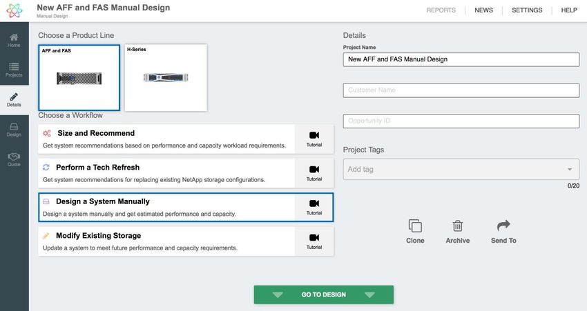
•       Disaster recovery group
•       Replication
•       Network
•       Storage

Disaster Recovery Group
MetroCluster IP uses the concept of disaster recovery for group and partners to determine the
relationship for failover and switchover. The two clusters (site A and site B) are configured together as a
disaster recovery group. Within the group, the nodes are associated as disaster recovery partners.
The HA relationship is the same as in a standard cluster. HA protects against single controller faults and
performs failover locally. HA is also leveraged for nondisruptive ONTAP updates. For site-wide faults, the
disaster recovery relationship is used to switch from site A to site B, which is referred to as switchover.
The disaster recovery partner relationship is configured in the initial MetroCluster setup and does not
change. There is one command that assigns one node from cluster A and one node from cluster B as
partners. The remaining nodes are automatically assigned to complete the disaster recovery group
configuration.

Figure 4) MetroCluster HA and disaster recovery.

Replication in MetroCluster IP
MetroCluster IP leverages direct attached storage, which eliminates the need for external SAS bridges to
connect disks to the storage fabric. Each node in the disaster recovery group acts as a storage proxy or
iSCSI target that exports its disks to the other nodes in the group. iSCSI (SCSI over TCP/IP) is the
storage transport protocol for the IP fabric that allows the iSCSI initiator and targets to communicate over
a TCP/IP fabric. Each node in the disaster recovery group accesses its remote storage through an iSCSI
initiator that establishes an iSCSI session with a remote disaster recovery partner iSCSI target.
The use of iSCSI and direct-attached storage also enables the use of systems that have internal disks.
iSCSI allows the nodes to provide the disaster recovery partner node access to internal storage in
addition to storage devices located in external disk shelves.
MetroCluster has three planes of replication:
1. Configuration replication

    8       MetroCluster IP Solution Architecture and Design                   © 2020 NetApp, Inc. All rights reserved.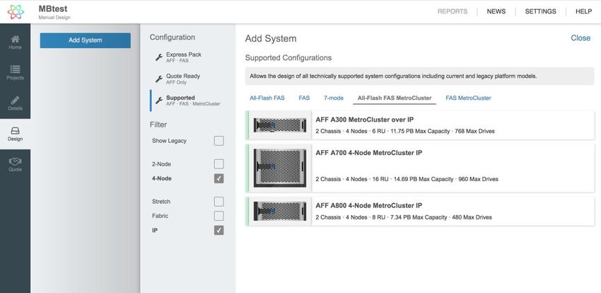
2. NVRAM replication
3. Storage replication

Configuration Replication Service
Configuration is replicated using the configuration replication service (CRS). CRS replicates the
configuration synchronously from the local node to the disaster recovery partner in the partner cluster.
This replication is carried out over the cluster peering network. The peering network is a customer-
supplied IP network with intercluster LIFs. The peering network for MetroCluster is the same as a regular
ONTAP cluster, such as the peering network used for ONTAP SnapMirror®. It can also be the same front-
end network that hosts use to access storage.
Note:      The cluster peering network is typically the front-end or host-side network. This traffic does not
           use the MetroCluster IP back-end storage fabric network.
The information, referred to as objects, that are replicated includes the cluster configuration and the
storage virtual machine (SVM) configuration. CRS replicates configuration objects between the clusters
including:
•       SVMs, LIFs, volumes, aggregates, and LUNs
•       Protocol objects such as CIFS, NFS, and SAN
New objects are transferred to the remote cluster as standby objects. Object updates are propagated as
they occur. If there is an interruption in the cluster peering network that affects CRS, replication catches
up automatically after the connection is re-established.
CRS requires a small volume on a data aggregate to store metadata referred to as the metadata volume..
Each cluster requires one volume that contains metadata.. Typically, this is only a concern when an
active-passive site configuration is being planned. In this case, a small volume in a data aggregate must
be created on the cluster in the passive site.

NVRAM Replication
NVRAM replication mirrors the local node NVRAM to the NVRAM for the remote disaster recovery node.
MetroCluster IP uses iWARP to replicate NVRAM over a TCP/IP connection. The iWARP protocol is
offloaded in hardware with RMDA-capable network adapters to make sure that latency is not affected by
the IP stack.

Storage Replication
Storage replication mirrors the local and remote back-end disks using RAID SyncMirror (RSM).
MetroCluster IP presents the back-end storage as logically shared by making each node in a disaster
recovery group serve as a remote iSCSI target. For a node to access its remote back-end disks, it goes
through its remote disaster recovery partner node to access the remote disks that are served through an
iSCSI target.
Figure 5 illustrates the MetroCluster IP planes of replication for NVRAM and storage. NodeB1 exports its
locally attached disks to remote partner nodes in the disaster recovery group through an iSCSI target.
NodeA1 pool0 disks are locally attached to NodeA1, whereas pool1 remote disks are exported through
the iSCSI target hosted by B1. The aggregate aggr1 node_A_1 local plex 0 consists of locally
attached disks from pool0. The aggregate aggr1 node_A_1 remote plex 1 consists of disks directly
attached to B1 and exported to A1 through the iSCSI target hosted in B1.

    9       MetroCluster IP Solution Architecture and Design                      © 2020 NetApp, Inc. All rights reserved.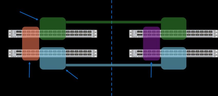
Figure 5) Mirroring write data blocks.

Blocks are written to both sides of the cluster with both NVRAM (or NVMEM) and SyncMirror. SyncMirror
writes data to two plexes for each mirrored aggregate, one local plex and one remote plex. SyncMirror
writes occur in the RAID layer, which means that any storage efficiencies such as deduplication and
compression reduce the data written by the SyncMirror operations.
Blocks read are obtained from the local storage and do not affect performance or use of the Inter-Switch
Links (ISLs) for read operations.

Encryption for Replication
MetroCluster does not provide a mechanism to encrypt data being sent between the sites. There are
currently two options for ensuring that site-to-site data is encrypted. NetApp recommends using a DWDM
device to encrypt all data going across the ISLs. However, not all implementations use a DWDM.
Alternatively, you can use host-side encryption of the data. The disadvantage is that this negates any
storage efficiencies that ONTAP normally provides.
Although it is possible to use NetApp Volume Encryption to encrypt data written to a volume, any writes
are also sent with NVRAM replication including unencrypted block data written by the host.

Network
There are two independent storage fabrics for MetroCluster:
•        MetroCluster IP network
•        Cluster interconnect
Each network is dedicated to certain functions. There are specific virtual LANs (VLAN) that map to each
of the networks to create separate data link layers, or layer 2 in the OSI standard.

    10       MetroCluster IP Solution Architecture and Design                © 2020 NetApp, Inc. All rights reserved.
Figure 6) MetroCluster IP combined fabric. NetApp provides a standard switch configuration known as a reference configuration file (RCF). RCF files are specific to the switch model and are available on the NetApp Support site in the software downloads section. The RCF files must be used to make any configuration changes to the switches. The RCF file is a bundle of four individual configuration files – one per switch. The RCF designates the VLAN and the channel group identifiers (IDs). These are used only within the back-end storage switches. There are specific requirements for IP addresses. See the MetroCluster IP Installation and Configuration guide for a worksheet and description of the requirements. Cluster Interconnect The ONTAP cluster interconnect is a local only network. The cluster interconnect does not connect between sites. All cluster traffic is local to the site where the nodes are located. On the MetroCluster IP switch, there are ports dedicated to the ONTAP cluster interconnect. There are two ISL ports that connect the two site switches together to pass cluster traffic forming a local VLAN that spans the switches. This provides redundancy for the local cluster interconnect. For nodes that connect at a non-native port speed, such as the NetApp AFF A300 all-flash storage system, there are designated ONTAP cluster interconnect node breakout ports. The AFF A220 and FAS2750 use cluster ports that share the same traffic with MetroCluster IP networking. The combined ports use VLANs to separate the MetroCluster IP traffic. If you order MetroCluster IP without switches because you already have existing compliant switches, the cluster interconnect ports are cross-connected to create a switchless cluster interconnect. This is a new feature for ONTAP 9.7. For more information, see section 0. MetroCluster IP Network Each site has two independent MetroCluster IP storage fabrics. Each fabric is connected to a similar remote fabric. The two local MetroCluster IP fabrics do not connect to each other. This is different from the cluster interconnect. On the MetroCluster IP switch, there are several ports reserved for MetroCluster IP node connectivity. Only two of the ports are currently used for a standard four node MetroCluster IP configuration that includes two nodes per site. Each of the two nodes connects to each switch. 11 MetroCluster IP Solution Architecture and Design © 2020 NetApp, Inc. All rights reserved.
For nodes that use the native port speed of the 100-Gb switch, ports 9 and 10 are used. These ports are
connected to VLAN 10 that is used for the MetroCluster IP storage fabric. For nodes that connect at a
non-native port speed, such as the AFF A300, there are specific MetroCluster IP node breakout ports
designated. For example, with an AFF A300 using the 100-Gb switch, the node ports are 25 and 26 on
the switch. These ports are configured to use the break-out cables and offer a 25-Gb port speed.
Node connections to the switch are provided by different Ethernet interfaces. The standard cluster
interconnect ports are used, typically onboard ports, or the same cluster interconnect interfaces available
for standard ONTAP HA configurations.
For the MetroCluster IP network, the Ethernet adapter is a specialized card that is optimized for the
internet-wide area remote direct memory access (RDMA) protocol (iWARP). In addition, this includes both
a TCP offload engine (TOE) and an iSCSI offload capability. iWARP provides RDMA over high-speed
Ethernet. The adapter is used for both iWARP and iSCSI traffic for local and remote replication. Each
node has two iWARP/iSCSI adapter ports installed and each port goes to a separate switch. Each switch
forms a separate fabric that is not connected locally as shown in Figure 6.
For the NetApp AFF A250, AFF A220, FAS500f, and FAS2750, software iWARP is used. These platforms
have a fixed number of network ports. To further enhance the use of network ports for front-end, host-side
data access, the two onboard 10GbE ports, e0a and e0b, that are typically reserved as cluster interfaces
are combined. This feature enables cluster traffic and MetroCluster IP traffic to share the same ports, and
the remaining four network ports can be used for host-side data access.
Note:   iWARP is a standards-based protocol described in IETF RFC 5040 – A Remote Direct Memory
        Access Protocol Specification.

Storage
Storage for MetroCluster IP is not directly shared across the two sites. It is not necessary to configure
unique shelf IDs across the sites. The storage at each site is only directly accessible by the local HA pair.
The remote storage is made available by the local nodes using iSCSI as described in the Storage
Replication section.

SyncMirror
SyncMirror, or RAID SyncMirror (RSM) is the technology used in MetroCluster to mirror the aggregates
between the sites. It enables two plexes to be configured in each aggregate, referred to as pool0 and
pool1. Pool0 contains the local storage for a node and pool1 contains the remote mirror copy.

ADP
As of ONTAP 9.4, MetroCluster IP supports Advanced Disk Partitioning (ADPv2) on AFF systems. ADP
allows a disk to be partitioned into one root and two data partitions. This allows a more granular disk
allocation for better use of capacity especially for creating more efficient root aggregates. With ADP, one
node owns a whole disk. Disks must be assigned to each node in the HA pair so that a node has capacity
for its root aggregates.
Note:   If you plan to nondisruptively transition workloads from a MetroCluster FC configuration to a
        MetroCluster IP configuration, ADP is currently not supported.
Disks are automatically assigned for configurations that use one, two, four or multiples of four shelves per
site. Other multiples require manual disk assignment as described in the installation guide.
See the MetroCluster IP Installation and Configuration Guide for more information about the ADP
configuration. The fusion sizing tool provides sizing for systems that support ADP.

 12     MetroCluster IP Solution Architecture and Design                       © 2020 NetApp, Inc. All rights reserved.
Solution Design
Proper design of a solution is the key to addressing performance, capacity, and resiliency requirements.
The overall steps for designing a solution include checking for supported hosts and platform
configurations as well as sizing to meet capacity and performance needs. The following issues must be
considered:
• Ensuring support for hosts and protocols
• Sizing of a solution for performance
• Sizing of a solution for capacity: active-active, active-passive configurations for capacity
• Reviewing systems limits
• Sizing ISLs between sites
• Cabling requirements
Confirming Support
Review the NetApp Interoperability Matrix Tool (IMT) to verify that the host-side protocol and operating
system versions are supported in the same way as any ONTAP design. Check any alerts noted in the
results pages to see if they apply to MetroCluster.
The Hardware Universe lists system specifications and supported limits. Starting with ONTAP 9.6, the
Hardware Universe also contains interoperability information for ONTAP 9.6 and later.
Sizing a Solution
A solution can be sized to meet specific storage capacity or performance requirements. MetroCluster
sizing is like sizing an HA pair with respect to capacity. With MetroCluster, the storage devices are double
the capacity used for an HA pair to provide the mirror copy of the data at the opposite site.
With respect to sizing the performance, the ISLs are a factor that can be accounted for using the ISL
sizing spreadsheet.
Fusion
Fusion provides sizing for MetroCluster using the AFF and FAS manual design capability as follows:
1. Log in to the Fusion portal: https://fusion.netapp.com/ (NetApp login required).
2. Select AFF and FAS, and then click the Design a System Manually button.
13 MetroCluster IP Solution Architecture and Design © 2020 NetApp, Inc. All rights reserved.3. Enter details about the project, then click the Go to Design button.
4. In the design page, click the Add System button. Choose Supported from the configuration types.
5. In the supported section, choose All-Flash FAS MetroCluster or FAS MetroCluster.
6. Select the desired platform configuration with MetroCluster IP.
Note: The filter defaults to 4-Node MetroCluster IP. If it has been changed, it is necessary to select
these filter settings.
7. After selecting the platforms, it is possible to select and add storage. If ADP is available, it is
automatically configured for a symmetrical layout.
14 MetroCluster IP Solution Architecture and Design © 2020 NetApp, Inc. All rights reserved.Note: Future versions of Fusion are planned to increase the options and functionality available for
sizing a MetroCluster solution.
Inter-Switch Link Sizing
The size and number of ISLs can be determined using a sizing spreadsheet. The spreadsheet allows you
to determine maximum performance based on the number and characteristics of the links. You can
access MetroCluster IP and FC ISL sizing spreadsheet on the NetApp Field Portal (login required).
It is also possible to evaluate ISL throughput using ONTAP when validation of link bandwidth is required.
Platform Limits
ONTAP limits are located in the Hardware Universe under the specific platform and ONTAP version. The
platform limits are at the bottom of the results page. Select MetroCluster IP from the Platform
Configurations menu to see the limits for an HA pair.
Figure 7) Hardware Universe platform limits.
Hardware Components
Hardware components include storage platforms, controllers, shelves, and storage fabric/cluster switches
and cabling. These are all detailed in the Interoperability Matrix Tool (IMT) and the Hardware Universe.
For details about the hardware components, see the MetroCluster IP Installation and Configuration
Guide.
MetroCluster IP Switches
The MetroCluster IP switches are platform. Each deployment requires four switches, two per site for
redundancy. It is not possible to mix the switch models in a single MetroCluster IP deployment.
See the Interoperability Matrix Tool on the NetApp Support site and the Hardware Universe for
information about supported switch models for a specific platform and version of ONTAP.
For port speeds lower than the native port speed, breakout cables are used. For example, when using
10Gb ISL links, breakout cables are used to connect the optical modules.
Table 1 describes the currently available switch models. See Hardware Universe for specifications.
Table 1) MetroCluster IP switch models.
NetApp PN Model Description Native Port Speed
X190200-CS-PE Cisco Nexus 9336C 40G/100Gb
X190001 Cisco Nexus 3132Q-V 40Gb
X190100 Cisco Nexus 3232C 100Gb
15 MetroCluster IP Solution Architecture and Design © 2020 NetApp, Inc. All rights reserved.NetApp PN Model Description Native Port Speed X190005 BES-53248 10/25Gb Figure 8) AFF A700 one site network example. Figure 9) AFF A300 one site network example. 16 MetroCluster IP Solution Architecture and Design © 2020 NetApp, Inc. All rights reserved.
Figure 10) AFF A220 one-site network.

Network Adapters
MetroCluster IP uses platform dependent specialized network adapters. The network adapters offer high-
speed Ethernet and the ability to offload iWARP operations. The adapters have dual ports to attach to the
two separate stretched layer 2 Ethernet fabrics.
Only one MetroCluster IP network adapter is supported per node and must be installed in a specific slot.
The MetroCluster IP network adapter provides the MetroCluster node to switch connection that is used for
storage and NVRAM replication.
There is a separate network adapter or network ports that are used for the cluster interconnect.
The AFF A220, AFF A250, FAS500f, and FAS2750 use software iWARP combined on the cluster
interfaces. This enables you to share traffic on the onboard e0a and e0b interfaces. This feature reduces
the port count required for back-end storage and provides the maximum number of ports for host-side
data interfaces.
The AFF A320 uses onboard ports for both cluster and MetroCluster IP networks.

Network Configuration
Network configuration requires that VLANs and IP addresses do not overlap with other networks. VLANs
are for the private back-end fabric and are assigned automatically in the switch RCF files. Before ONTAP
9.6, RCF files were created by switch model, platform, and ONTAP release. Starting with ONTAP 9.6,
there is a new RCF File Generator utility that is described on the RCF downloads page on the NetApp
Support site downloads section. With the new utility, you can create RCF files for all MetroCluster IP
switch models and supported platforms. It can generate RCF files with customer-provided VLAN IDs in
support of a shared layer-2 site-to-site network.
Note:    AFF A220 and FAS 2750 do not enable changing the VLAN IDs in ONTAP 9.7 and earlier. The
        required VLAN IDs are VLAN 10 and VLAN 20. However, in ONTAP 9.8, the VLAN for AFF A220,
        AFF A250, FAS 2750, and FAS500f can be specified. The default is 10 and 20, the user specified
        VLAN greater than 100 and less than 4096.

 17     MetroCluster IP Solution Architecture and Design                     © 2020 NetApp, Inc. All rights reserved.
Figure 11) RCF File Generator. In a typical switch configuration, most of the ports are open for future expansion. The switches create two redundant fabrics. Each node has a cluster connection and a MetroCluster IP node connection. There are several choices for cabling depending on the distance of the nodes to the switches. If possible, the optimal solution is to locate the nodes and the switches in the same equipment rack. This enables the use of copper Twinaxial cabling rather than requiring optical cabling. The switches are capable of native port speed, either 10/25Gbps, 40Gbps or 100Gbps depending on the model. The native ports are also capable of operating in break-out mode. In this mode, the port is divided into four separate lanes that are used as individual interfaces. When operating in break-out mode, a port on the 40-Gb switch can operate as four 10Gbps interfaces that are also dependent on the cable or optical module. Not all optical modules support break-out mode. The 100-Gb switch supports break-out mode as well. When operating at native port speed, a single physical interface operates as four 25Gbp interfaces. Specific cables and optical modules support operating in break-out mode. The 100-Gb switch can operate ports at 40Gbps for compatibility with 40Gb cables and optics. The 100-Gb switch also supports break-out mode when operating ports at 40Gbps. This provides four separate 10Gbps interfaces for each physical port. The RCF files preconfigure the break-out ports for the specific speeds required for each platform. 18 MetroCluster IP Solution Architecture and Design © 2020 NetApp, Inc. All rights reserved.
Note: It is possible to launch the RCF File Generator from the command line. The JAVA_HOME
      environment variable should be set. To run the RCF File Generator, enter the command as
      follows:
java -jar RcfFileGenerator.jar

Figure 12) MetroCluster IP 100Gb switch port assignments.

Figure 13) MetroCluster IP 40Gb switch port assignments.

Figure 14) MetroCluster IP 10/25Gb switch port assignments.

AFF A700 and FAS9000 MetroCluster IP Node to Switch Connections
Each node requires four connections to the switches, two to each local switch. The selection of cables
depends on the distance from the node to the switch. Shorter distances can use the lower-cost copper
Twinaxial cables. The result is eight copper cables at each site for node to switch connections.
Note:   The NetApp AFF A700 all-flash storage system MetroCluster IP node connection is only
        supported at 40Gbps with the 100-Gb switch.

 19     MetroCluster IP Solution Architecture and Design                    © 2020 NetApp, Inc. All rights reserved.
Figure 15) AFF A700 node to switch network connections.
Option 1: AFF A700 Using Copper Cables for Up to 5m Distance Between Nodes and
Switches
These cables are supported for both the MetroCluster IP and cluster connections.
Table 2) Supported copper cables for AFF A700.
Distance Cable PN Description
Less than 3m X66100-3 Cable, Copper, QSFP-QSFP, 40GbE, 3m
Less than 5m X66100-5 Cable, Copper, QSFP-QSFP, 40GbE, 5m
After the cables are selected, the configuration should include enough cables for both sites, typically with
all of them the same length. Because the same cable is used for cluster and MetroCluster IP networks,
there are four cables required per node.
Table 3) AFF A700 MetroCluster IP and cluster interconnect node to switch cables.
Quantity
Cable PN Description
Node Site Total
X66100-3 Cable, Copper, QSFP-QSFP, 40GbE, 3m 4 8 16
Option 2: AFF A700 Using Optical Cables for Up to 400m Distance Between Nodes and
Switches
Each node requires four optical transceiver modules, two for each node-to-local-switch connection. There
are four corresponding optical transceiver modules required for the switches for each node.
Optical module for AFF A700 MetroCluster IP and cluster interconnect – node ports
• X65402 QSFP+, 40GbE, Shortwave
20 MetroCluster IP Solution Architecture and Design © 2020 NetApp, Inc. All rights reserved.Optical module for switch MetroCluster IP and cluster interconnect – switch ports
• X65401 QSFP+, 40GbE, Shortwave
Note: The optical modules for the Ethernet adapter in the node are not the same as the optical
modules for the switch ports.
Fiber cables are also available in several lengths. The maximum distance depends on the type of cable. It
is possible to extend to 300m on OM3 multimode fiber (MMF) and 400m on OM4 MMF. You should
consult with a network cabling specialist for specific configurations. The use of patch panels affects the
signal quality, which in turn affects the distance that is possible.
These cables are supported for both the MetroCluster IP and cluster connections.
Table 4) OM4 fiber optic cables.
Length Cable PN Description
2m X66200-2 Cable, Fiber, OM4 MPO-MPO, 2m
5m X66100-5 Cable, Fiber, OM4 MPO-MPO, 5m
15m X66200-15 Cable, Fiber, OM4 MPO-MPO, 15m
30m X66200-30 Cable, Fiber, OM4 MPO-MPO, 30m
Figure 16) Optical connection.
AFF A250, AFF A300, FAS500f, and FAS8200 MetroCluster IP Node to Switch
Connections
The AFF A250, AFF A300, FAS500f, and FAS8200 platforms have 10Gb and 25Gb network ports. The
ports are connected to the switch to specific ports that are configured in break-out mode in the RCF. The
two types of connections; cluster, and MetroCluster IP, use different node network ports and cables. The
cluster interconnect uses the onboard 10GbE interfaces and the MetroCluster IP uses 25GbE interfaces
on the MetroCluster IP network adapter. This requires the use of two different cable types that correspond
to the 10-Gb cluster ports and the 25Gb MetroCluster IP ports, respectively.
Note: AFF A250 and FAS500f do not support Open Networks,
Note: This section describes the cabling required for the Cisco 3232C 100Gb switch.
The cluster interconnect for the AFF A250, AFF A300, FAS500f, and FAS8200 uses the onboard 10GbE
ports. The node’s cluster ports connect to the switch using a break-out cable. The break-out cable and
RCF configuration settings convert some of the 100-Gb switch ports to four 10-Gbps links. A single link is
used per cable.
Supported Cluster Node to Switch Cable for Use with the AFF A250, AFF A300,
FAS500f, or FAS8200
Four cables are required per site, and each cable connects one 10-GbE port on the node to one port on
the switch that is configured for break-out mode.
21 MetroCluster IP Solution Architecture and Design © 2020 NetApp, Inc. All rights reserved.Table 5) AFF A300 cluster interconnect node to switch cables.
Quantity
Cable PN Description
Node Site Total
X66120-3 Cable, Cu, 40GbE, QSFP+/4xSFP+, 3m 2 4 8
The MetroCluster IP node connection uses a different break-out cable connected to the MetroCluster IP
Ethernet adapter at 25Gb. This cable and corresponding RCF configuration settings converts a switch
port to four 25-Gbps links. A single link is used per cable.
Supported MetroCluster IP Node to Switch Cable for Use with the AFF A250, AFF
A300, FAS500f, or FAS8200
Four cables are required per site, and each cable connects one 25-GbE port on the node to one port on
the switch.
Table 6) AFF A300 MetroCluster IP network node to switch cables.
Quantity
Cable PN Description
Node Site Total
X-QSFP-4SFP25G-CU2M Cable, Cu, 25GbE, QSFP+/4xSFP+, 2m 2 4 8
Figure 17) AFF A300 node to switch network connections.
AFF A220 and FAS2750 MetroCluster IP Node to Switch Connections
The AFF A220 and FAS2750 can use the Broadcom-supported BES-53248 (NetApp P/N: X190005)
10/25Gb switch for a more economical solution. You can also use the 40Gb and 100Gb Cisco switches
with the AFF A200 and FAS2750 platforms.
AFF A400, FAS8300, and FAS8700 MetroCluster IP Node to Switch Connections
The AFF A400, FAS8300, and FAS8700 can use the Broadcom-supported BES-53248, Cisco Nexus
9336C and Cisco Nexus 3232C 100Gb switches.
22 MetroCluster IP Solution Architecture and Design © 2020 NetApp, Inc. All rights reserved.Cluster Fabric ISL
The cluster interconnect fabric is local to a site. Each switch has dedicated ports to the local cluster Inter-
Switch Link. The cluster ISL uses native port-speed copper cables.
MetroCluster IP ISL Link Design
ISLs are site-dependent and can be the more complex part of architecting a MetroCluster IP solution.
This is because of the significant variety of site-to-site links and distances between sites.
Designing an ISL configuration includes doing sizing calculations for the links to determine how many
links are required to meet a certain performance from the storage platform. There is an existing sizing tool
for performing this calculation on the NetApp Field Portal (login required). The result from the tool
provides the number and size of links mapped to the performance of the platform.
The next steps are to determine the components required for each link and the distances that are
supported. The distance possible for a link depends on several factors. The ONTAP software version has
a maximum supported distance for the ISL link shown in Table 7.
Table 7) ISL maximum characteristics.
ONTAP Release Maximum Distance Maximum Round-Trip Latency
9.5 and later 700km 10ms
9.3, 9.4 100km 1ms
For ONTAP 9.5 and later, the site-to-site connection should have a maximum path round trip time (RTT)
of 7ms, which is approximately 700km if the latency is purely from distance. In addition to 7ms, a jitter of
up to an additional 3ms is supported, providing a maximum latency in cases when the network is glitchy
of up to 10ms, as is noted in the preceding table.
There are several other factors that determine the possible distance for the configuration. Optical
modules and matching optical cable configurations provide various maximum supported distances.
Multimode optics and cables provide shorter distances at a lower cost. For longer distances, long-range
optics and single-mode fiber are required.
For maximum distances, you should consult with the telecommunications provider. Long-distance links
use specific telecommunications equipment that can include amplification of the signal to extend the
range beyond the optical module’s capabilities.
For configurations that are within a single data center, separated by racks in separate availability zones, it
might be possible to use standard Ethernet cabling. This greatly simplifies the design and can provide
ISLs at native switch port speeds of either 25Gb, 40Gb or 100Gb depending on the switch and modules.
Factors to consider for MetroCluster IP ISL:
• Storage performance requirements
• Existing customer site-to-site network capabilities
• Direct fiber availability
• Multiplexing devices
• Distance: rack to rack, campus, or site distance
• Existing fiber infrastructure (cabling, connectors, patch panel connectors)
Rack-to-Rack: Short Distances
For MetroCluster IP configurations that are within a data center and have close proximity between the
sites, it might be possible to use copper cabling for the ISL links. This is often the case with laboratory or
23 MetroCluster IP Solution Architecture and Design © 2020 NetApp, Inc. All rights reserved.test configurations. Table 8 and Table 9 show the part numbers for the switch to switch copper cables for both the 40Gb and 100Gb switches. Table 8) 40Gb 3m to 5m distance between switches (approximate cable length). Distance Cable PN Description Less than 1m X66100-3 Cable, Copper, QSFP+-QSFP+, 40GbE, 1m Less than 3m X66100-3 Cable, Copper, QSFP+-QSFP+, 40GbE, 3m Less than 5m X66100-5 Cable, Copper, QSFP+-QSFP+, 40GbE, 5m Table 9) 100Gb 3m to 5m distance between switches (approximate cable length). Distance Cable PN Description Less than 1m X66211A-1 Cable, Copper, QSFP28-QSFP28, 100GbE, 1m Less than 2m X66211A-2 Cable, Copper, QSFP28-QSFP28, 100GbE, 2m Less than 5m X66211A -5 Cable, Copper, QSFP28-QSFP28, 100GbE, 5m Similarly, the use of optical cabling between racks is possible. This enables a simple ISL configuration when the distances are within the specification of the optical modules. Table 10) Short-range optical module for 40GbE switch. Distance Module PN Description Up to 400M on OM4 X65401 XCVR, QSFP+, Optical, 40GbE, Shortwave Table 11) Short-range optical module for 100GbE switch. Distance Module PN Description Up to 100M on OM4 X65405 XCVR, QSFP28, Optical, 100GbE, Shortwave Table 12) 40Gb and 100Gb optical cables. Length Module PN Description 2M X66200-2 Cable, Optical, OM4, MPO/MPO Type B 5M X66200-5 Cable, Optical, OM4, MPO/MPO Type B 15M X66200-15 Cable, Optical, OM4, MPO/MPO Type B 30M X66200-30 Cable, Optical, OM4, MPO/MPO Type B Campus Links Campus links that use direct fiber connections between short distances can be similar to using rack-to- rack ISLs. One potential difference is the use of long-range optics and single-mode cabling to achieve longer distances compared to multimode cabling and short-range optics. Currently, NetApp does not offer long-range optical modules for either the 40GbE or 100GbE switches. For designing links that require long-range optics, see the Cisco support matrix for the specific switch model and the Cisco optical module datasheets to determine distance and connection specifics. Dedicated Fiber Links Dedicated fiber links are more common for campus networks connecting buildings located in proximity. With dedicated fiber links, you might want to multiplex signals from many fiber connections onto fewer fiber links. Doing this can maximize utilization and reduce the required number of fibers between the site. Multiplexing of optical signals is called wavelength division multiplexing (WDM) and it is available in two 24 MetroCluster IP Solution Architecture and Design © 2020 NetApp, Inc. All rights reserved.
types, coarse wavelength division multiplexers (CWDM) and dense wavelength division multiplexers
(DWDM).
CWDM can multiplex a smaller number of wavelengths compared to DWDM.
CWDMs are commonly passive devices that optically multiplex and demultiplex the light from the optical
modules into a single signal that can be transmitted across a single fiber pair. The optical modules are
wavelength specific, sometimes referred to as channel. To multiplex two different fiber signals, each
source signal must be generated from an optical module that uses a different wavelength. CWDM optical
modules are available from Cisco and support eight different wavelengths. This enables the multiplexing
of eight fiber signal links onto a single fiber link. The CWDM multiplexer is passive and only contains
optics that multiplex and demultiplex the signals. This typically is a lower cost for multiplexing devices and
associated optical modules compared to DWDM.
DWDMs use a similar method for merging signals as CWDM devices. The primary difference is that the
optical modules are more precise in the signals they generate, enabling a narrower spectral width for a
narrow signal and less spacing between the signals. This enables a higher number of signals to be
combined for transmission on a site-to-site fiber link. DWDM devices can be active or passive. Passive
devices use the same approach as CWDM where the optical modules transmit a specific wavelength or
channel that is merged in the DWDM device to produce a single signal. This signal is transmitted on the
longer distance fiber cable between the sites.
DWDM devices are also available as active devices. In this case, the signals between the switch and the
DWDM device use standard optics and rely on the DWDM device to produce a signal at the wavelength
that can be merged onto the site-to-site fiber link.
For distance, the optical modules provide specifics on the allowable distance and the link characteristics
required to meet the specifications. Transmitting at longer distances might require a signal amplifier.
There are several types of amplifiers that apply for DWDM such as an optical amplifier. NetApp
recommends consulting with a telecommunications specialist to help design the optimal configuration.
Cisco provides 10Gb SFP+ modules that can be used for coarse or dense wavelength multiplexing.
xWDM enables multiple optical signals to be combined or multiplexed on a single fiber pair between sites,
then demultiplexed before routing the signal to a switch or device.
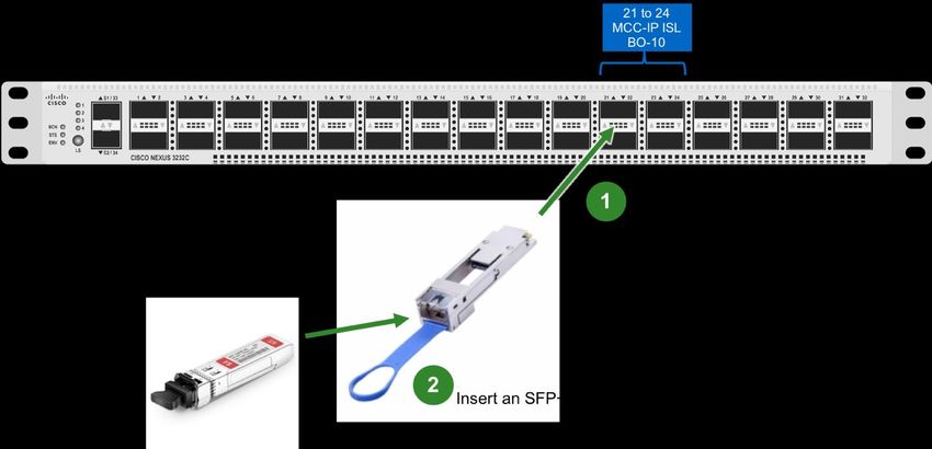
Figure 18 is an example of using a passive DWDM and shows a possible mapping for the optical modules
on specific channels. All the optical modules for each site use a unique channel. Match the opposite site
B optic, same channel.
Example using DWDM modules
• Site A switch 1 port 21 – Site B switch 1 port 21 using two optical modules on channel 40
• Site A switch 2 port 21 – Site B switch 2 port 21 using two optical modules on channel 41
• Site A switch 1 port 22 – Site B switch 1 port 22 using two optical modules on channel 42
• Site A switch 2 port 22 – Site B switch 2 port 22 using two optical modules on channel 43
25 MetroCluster IP Solution Architecture and Design © 2020 NetApp, Inc. All rights reserved.Figure 18) Site A passive DWDM example using 10Gb optical modules and QSA.
The first module in the example is Cisco part number DWDM-SFP10G-45.32, that is a 10GBASE-DWDM
SFP+ module operating on the 1545.32-nm wavelength (100-GHz ITU grid) which is ITU channel 40. To
complete the configuration in this site, three more modules must be supplied each corresponding to
channels 41, 42 and 43. Site B then contains the exact same configuration of optical modules, port
adapters, and passive DWDM.
Intercity Links
For the longest distance links, active DWDM or Telco circuits are often used. Connection from the switch
to most telecommunications or active DWDM devices is done with the same optical modules that would
be used in a data center or rack-to-rack configuration. See section “Rack-to-Rack: Short Distances” for
rack-to-rack cabling and modules.
Note: Depending on the equipment, it is also possible that an active DWDM can provide encryption of
the ISL traffic.
NetApp recommends that you consult with a telecommunications specialist to help design the optimal
configuration for intercity links.
26 MetroCluster IP Solution Architecture and Design © 2020 NetApp, Inc. All rights reserved.You can also read