EXO GeminEye HD Camera System QPT-LT Positioner
←
→
Page content transcription
If your browser does not render page correctly, please read the page content below
Installation and Operation Instructions
                                                                              Before attempting to connect or operate this product, please
                                                                              read these instructions completely.

EXO GeminEye
HD Camera System QPT-LT Positioner

                                                            Moog Inc.
                                                Sensor and Surveillance Systems
                                             3650 Woodhead Drive Northbrook, IL. USA 60062
© 2013, Moog Inc. All Rights Reserved                                                                                               MN00178
                                        +1.847.498.0700 Fax: +1.847.498.1258 www.moogS3.com
Table of Contents
SECTION I                   GENERAL INFORMATION..................................................................................................................................................…….3
		Scope.............................................................................................................................................................................................................3
		 Purpose of the Equipment.................................................................................................................................................................................3
		 Description of Equipment..................................................................................................................................................................................3
			Models…………….………….........…………………………………………………………..................................................3
		Specifications..................................................................................................................................................................................................4
			PAN & TILT……………………………………………………..................................................................................................4
			CAMERA HOUSING……………………………………...............................................................................................................4
			CONTROL………………………….................................................................................…........................................................4
			ACCESSORIES………………………………………….....................................................……………………………………5

SECTION II                  INSTALLATION..........................................................................................................................................................................5
		General:..........................................................................................................................................................................................................5
		 Unpack and Inspect:........................................................................................................................................................................................5
		Installation:......................................................................................................................................................................................................5
			GENERAL:………………………………………………………………...................................................................................5
			            INSTALLATION PROCEDURES – MECHANICAL:……………………………………………….........................................................5
			            INSTALLATION PROCEDURES – ELECTRICAL:……………………………………………….........................................................7
			            INSTALLING / UNINSTALLING – CAMERA ASSEMBLY……...………………………………….........................................................7
		 INTERNAL ACCESS & ADJUSTMENT.................................................................................................................................................................7

SECTION III                 THEORY OF OPERATION............................................................................................................................................................8
		General:..........................................................................................................................................................................................................8
			OVERVIEW……………………………………………………………………………………………......................................8
			LOGIC CONTROL BOARD………………………………………………………………………….............................................8
			OPTO POSITION DETECTORS……………………………………………………………….......................................................8
			DRIVE SYSTEM………………………………………………………………………………………......................................8
			           COMMUNICATIONS & CONTROL BOARD………………………………………………………...................................................8

SECTION IV                  TEST SOFTWARE......................................................................................................................................................................9
		SOFTWARE SETUP...........................................................................................................................................................................................9
			Moog Configuration Tool…………………………………………………………………………….........................................9
		 Using the Moog EXO Web Application..............................................................................................................................................................12
			Application……………………………………………………………………........................……………............................12
		System Status...............................................................................................................................................................................................13
		Configuration.................................................................................................................................................................................................14
			Configuration / Date Time………………………………………………………………………………………………........14
			Configuration Network……………………………………………………................................................................................15
			           Configuration / Network / DHCP......................................................................................................................................................15
			           Configuration / Network / Host Name Configuration-NPT...................................................................................................................15
			           Configuration / Network / HTTP.......................................................................................................................................................15
			           Configuration / Network / API- Boujour............................................................................................................................................16
			           Configuration / Network / SNMP Configuration.................................................................................................................................16
			           Configuration / Network / RTSP Configuration..................................................................................................................................16
			           Configuration / Network / Multicast.................................................................................................................................................16
			           Configuration / Video In / Video Input..............................................................................................................................................17
			           Configuration / Video In / Sensor....................................................................................................................................................17
			           Configuration / Video In / Video Compression...................................................................................................................................18
			           Configuration / Video In / Point to Point...........................................................................................................................................18
			           Configuration / Video In / Text Overlay.............................................................................................................................................19
			           Configuration / Video In / Motion Detection......................................................................................................................................20
			           Configuration / Video In / Privacy Zones..........................................................................................................................................20
			Configuration / Audio Out...............................................................................................................................................................21
			Configuration / User Accounts........................................................................................................................................................22
			Maintenance.................................................................................................................................................................................23
		Live Viewer....................................................................................................................................................................................................24
			           Live Viewer Pan / Tilt and Presets...................................................................................................................................................25
		 Performing Batch Firmware Update.................................................................................................................................................................26
			           Point to Point Connections.............................................................................................................................................................28
		Troubleshooting Guide....................................................................................................................................................................................28

MN00178                                                                                                                                                                                                          1359
SECTION I GENERAL INFORMATION
Scope
This manual provides information expected to be used in installing, adjusting, and operating the EXO HD GeminEye™ System.
CAUTION: READ THIS MANUAL COMPLETELY BEFORE CONNECTING POWER TO THE UNIT. INJURY TO PERSONS, AND DAMAGE TO THE UNIT OR
ASSOCIATED EQUIPMENT CAN OCCUR IF THE UNIT IS NOT USED PROPERLY.
Purpose of the Equipment
This device is to be used to provide azimuth and elevation positioning for one HD daylight camera, and if desired an optional thermal camera. Other configurations include
a HD daylight camera and Illuminator. Remote control of position, and camera functions are possible with this system.
The modular camera(s) may be positioned to any degree of azimuth within a continuous 360 degree circle. The camera elevation can be moved to any angle from horizontal
to approximately ±90 degrees. Hard mechanical limit stops are factory set to approximately ±95 degrees. Software adjustable limits (soft limits) are factory set to ± 90°.
Description of Equipment
The EXO HD GeminEye is designed to be operated by Internet Protocol (IP) control, and each EXO camera housing contains a IP Video Encoder. The video encoder has two
functions:
• Convert the video signal to a streaming signal that can pass over the internet to the user, allowing them to see the video image.
• Provide a separate control channel that will allow control of GeminEye.
Single camera models will have one active IP connection to the GeminEye while dual camera models will have two. The GeminEye HD visible camera video is fed to the
video encoder, which in turn streams video through the IP connection. Control communication to the GeminEye passes through the IP connection to the video encoder
housed in the camera housing, and is then sent to the positioner's main control microprocessor to provide the user control of the positioner. In models with both a visible
and thermal camera, either channel can be used to operate and move the GeminEye. GeminEye will respond to Moog commands as outlined in the "PTL-11 Protocol"
document, or to specific Pelco® commands, as outlined in the protocol document MN00177, included on the CD-ROM accompanying the product. All control command
must be wrapped with IP.
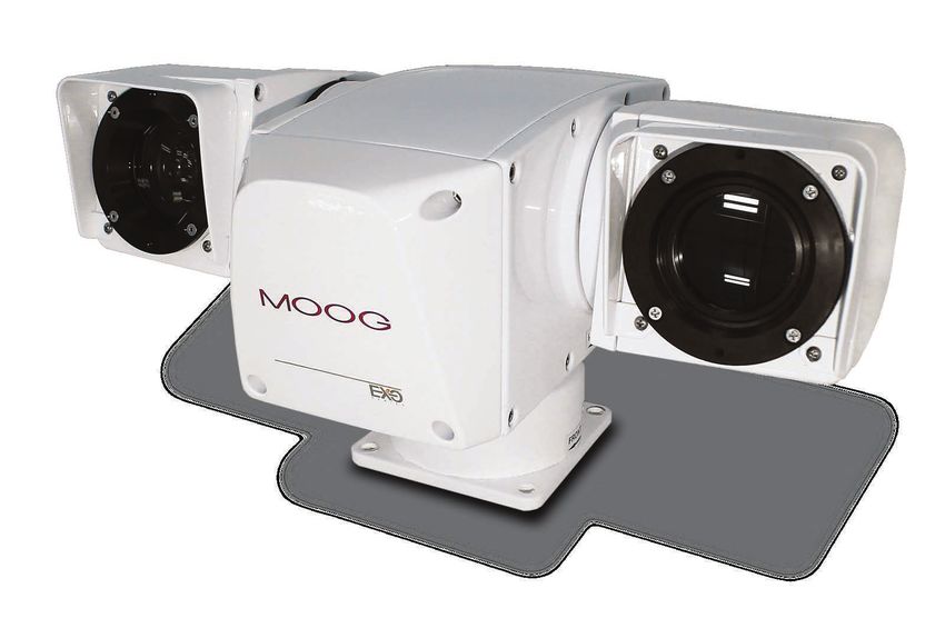
The HD GeminEye is constructed primarily of aluminum, is approximately 7.25" (184.15 mm) high by 10.5" (266.70 mm) deep by 14.25" (361.95 mm) wide, and weighs
approximately 24 lbs. (10.89 kg) with dual cameras. Its general configuration and major dimensions are shown in Drawing 1 in Appendix II.
No access is needed inside the positioner. There is no requirement for lubrication or periodic inspection.
A quick release system allows removing the camera housing(s) for quick replacement with "plug & play" capability. The camera housings as shipped are pressurized with
5 psi (max.) of dry nitrogen to prevent condensation.
The pan & tilt housing encloses the pan and tilt motors, belt drive assemblies, azimuth slip-ring, tilt hard limit stops, pan & tilt position optical position sensor assemblies,
power supply board, and a microprocessor control board. The power supply board supplies power for the camera(s), and raw input power (unconditioned 10 - 30 VDC)
input is sent to the camera enclosure(s) for the heaters. The camera housing assembly consists of a front glass window assembly (daylight camera), connectors/cables
for connecting camera, a camera interface board, & heater(s). The camera interface board decodes the universal serial buss commands and converts them to the specific
camera commands required for the specific camera. Each camera module contains a video encoder, which has channels for video and control. The video from each module
is streamed separately, allowing both to be visible at the same time. The control channels from both encoders are wired directly to the main controller PCB in the positioner
section. This board processes incoming commands, performs and manages pan & tilt functions, and routes camera commands to the camera(s) via a universal serial buss.
(In some models, camera commands are sent directly from the video encoder to the camera) The camera commands include camera/lens control where applicable.
Power and control signals enter the unit through a water tight connector exiting out the bottom of the unit. The mil spec mating connector and test cable are supplied.
The equipment uses o-ring seals and gaskets for the camera enclosure and pan & tilt housing to provide environmental protection. The camera housings are sealed and
should be pressurized with dry nitrogen at no more than 5 psi.
Models
All models consist of a LT-EXHDO1 center section positioner for single and dual camera models, or a LT-EXHD02 center section positioner for specific illuminator models.
Visible camera block available include models using the Sony FCB-EH6500 HD color camera, and the Sony FCB-EH6300 HD color camera.
Thermal vision blocks are available using the FLIR Tau 640 imager or the FLIR Tau 320 imager each with a variety of lenses ranging from 25mm to 100mm fixed lenses,
and a 15mm to 100mm continuous zoom lens. Normal and slow frame rate version availability is subject to ITAR regulations.
EXO GeminEye models are also available with visible cameras and illuminators, where additional illumination may be required to enhance the image during low
light conditions.
MN00178 1359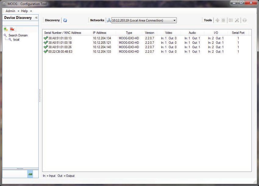
Specifications

PAN & TILT

TInput Voltage		              10 to 30 VDC

Power Requirements		          Positioner w/Visible camera requires 60W during initialization or at start of move,30W during continuous motion, 11W at idle. If heaters
			                           are activated, an additional 72W is required. The FLIR Tau camera used in thermal imager models requires an additional 1.2W
			                           (approximate). Illuminator requires 45W, provided on separate power leads

Pan Range			                  Continuous pan rotation, non-continuous selectable. Soft limits adjustable for non-continuous pan, no soft limits for continuous pan

Pan Speed Range		             0.25º to 100º /sec with QuickShift® technology

Tilt Range Mounting		         Soft limits adjustable to ±90º max. (180º total) from horizon (parallel to P&T surface.) Factory default setting is 90º down, 90º up. Hard
			                           stops set approximately ±95°

Tilt Speed Range 		           0.25º - 100º / sec. with QuickShift® technology

Motor Type			                 Stepper motors are used for both Pan and Tilt axis

Wiring			                     26 Pin Connector on bottom of unit

System Dimensions (H x W x D) 7.25" x 14.25" x 10.5" (185 x 362 x 266.7mm)

System Weight                 24 lbs. (10.9 kg) approximately with dual cameras

Drivetrain          		        Belt driven stepper motors with high torque timing belts

Tilt Limit       		           Internal, fixed stops, adjustable soft limits

Repeatability		 0.25º

Material			                   Housings - Aluminum, Hardware - Stainless Steel

Exterior Color / Finish		     White Marine Powder Coated (other colors & custom colors/private labeling upon request)

Environmental Enclosure       Gasketed & sealed, IP-66 rated

Operating Temperature         -40˚ to 122˚F (-40˚ to 50˚C) with heaters

Position Feedback 		          Motor pulse count and optical position sensors, position resolution to 0.01º.

CAMERA HOUSING
Environmental Enclosure       O-ring seals and pressurizable (5 psi max)

Heaters			                    Camera housing heater(s) (thermostatically controlled)

Hardware/Wiring		             Stainless hardware and concealed wiring

CONTROL
Communication modes:          Ethernet TCP/IP for each camera and positioner control. Supports QuickSet PTL-11 and Pelco-D Extended command & control protocols,
			                           Camera interface board required for each specific camera. Basic test software for Windows™ provides capability to configure, test, and
			                           operate the Pan & Tilt 32 Preset positions - each storing azimuth, elevation, zoom, & focus. 2 tours of 63 steps of 32 presets with easy
			                           insert editing capability. Capability of entering absolute angle offsets to align pan and tilt platform to user coordinate base. Align local
			                           coordinates to global coordinates. Automatic calibration as required using internal optical position sensors. ™Windows and
			                           Microsoft are registered trademarks of Microsoft Corporation.

MN00178                                                                                                                                                                 1359
ACCESSORIES
Included accessories:

           • 10' indoor test cable included with product, terminating with RJ45 connectors for Camera 1 & Camera 2, #6 spade lugs for GeminEye power, Illuminator
             power, chassis ground.
           • Connector for user installation QuickSet part number QS50495 (generic MS3116F16-26SW). Note that customer should supply an appropriate connector
             back shell for outdoor installation to provide weather sealing appropriate to the installation.

Available accessories:

           •    7-17564 Kit - Curved Wall Mount Bracket
           •    7-17565 Kit - Adapter w/Chain-Strap for Pole Mount, use with 7-1756
           •    7-17566 Corner Mount for use with 7-17564
           •    7-17567 Pedestal Mount for mounting on Horizontal surface

SECTION II			INSTALLATION
General:
To achieve optimum results from this unit, proper installation procedures should be followed, primarily: location, mounting, & setting soft tilt limit stops. These items are
reviewed in the following sections.

Unpack and Inspect:
Carefully remove the unit from the carton and examine for signs of physical damage, particularly dented or broken parts. If any are observed, notify the freight carrier im-
mediately for claim handling. Retain all packing material until claim is settled.

Check the box contents for (1) Integrated Camera System, (1) mating connector, (1) test cable, (1) basic test software/manuals CD00556, and (1) system schematic. If any
of the above components are missing, please contact Moog immediately, and please have your sales order number available. Claims for missing components must be filed
within a reasonable time period from receipt. Retain packing box if future shipping or storage is expected.

Installation:

GENERAL:

To achieve optimum and safe results from this unit, proper installation procedures should be followed as described in section "B"; primarily these have to do with the Pan
& Tilt location and settings of the limit stops. These items are reviewed in the following paragraphs.

INSTALLATION PROCEDURES - MECHANICAL:
Site Location

Select a mounting location that will provide the desired maximum movement angles without allowing the pan and tilt or camera enclosure to come in contact with, or strike,
any objects in their sweep paths. Adjustable soft limits should be set to limit the degree of travel in tilt, (soft limits are set in software). Refer to the drawings below to see
the dimensions of the EXO product. Dimensions shown in brackets are metric [millimeters] while other dimensions are in inches.

Figure 1:
Standard EXO Visible /
Thermal camera version.

MN00178                                                                                                                                                                        1359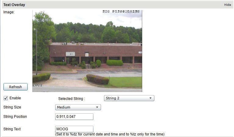
Figure 2:
EXO Visible / Thermal
with Zoom lens version.

Mounting
The mounting base is drilled with four holes on a 4.75" diameter bolt circle in a 4.0" square base, sized for 1/4" screws. If mounted in a position other than horizontal, the
payload capacity may be reduced. Fasten the base to a stable platform. We recommend 1/4-20" high strength stainless steel bolts and nuts be used. Consideration of wind
and ice load is important when calculating how solid the mounting platform needs to be and the strength required in the mounting screws.

Figure 3:
Base mounting dimensions.
Dimensions shown in brackets
are metric [millimeters] while other
dimensions are in inches.

A selection of QuickSet Mounts are available for wall, pedestal, corner, and pole mounting. When used with the QuickSet wall mount bracket, these provide adequate
clearance for a full 360 degree continuous pan rotation with no interference. Contact your regional Business Development manager for information regarding these
components.

Internal Access
Access to the interior of the pan & tilt housing is not required.

Setting of Pan & Tilt Soft Limit Stops
The tilt soft (software settable) limit is factory set at ±90 degrees. They can be adjusted to values less than the ±90 degree range. There is no pan soft limit in continuous
mode, but there are user adjustable soft limits in the non-continuous rotation mode, when using the Moog PTZ controller. Refer to MN00307.

MN00178                                                                                                                                                                   1359
INSTALLATION PROCEDURES – ELECTRICAL:

General Comments
The interface cable between the computer and integrated camera system is important to the reliable operation of any motorized instrument positioning system. Selection
of the type of cable, the size (AWG), the number of conductors required, grounding techniques, special consideration for wiring to the devices mounted on the pan/tilt unit,
plug connections and the pan/tilt options are the topics covered in this Section.

Wire Selection
Careful consideration should be given to the type of cable utilized in order to achieve long-term reliability and avoid costly system modifications. The type of cable instal-
lation, such as, underground, overhead, pole mounted generally requires cable designed for the specific application. In addition, the wire may have to be run in conduit.
Check your local electrical code. Adequate wire size insures that sufficient voltage will reach the pan/tilt motors, which will provide the required torque to move the camera.
One factor that influence the wire size is the distance between the power supply and the pan/tilt unit. The current draw is approximately 5.625 amps (135 W @ 24VDC)
with a dual camera system. Size the connecting wires to minimize voltage drop to the positioner based on distance from the power source.

Mating Connector Installations
Pan / Tilt Site - A mating connector is provided. Carefully solder the cable leads to the Pan / Tilt mating receptacle pins. Refer to the appropriate schematic and / or
connector diagram.

Connector Pin         Signal Description           		             Conductor used on Test Cable
A		Input Power, +10-30 VDC		Red 			18 AWG
B		Input Power, 0 VDC (return)		Black			18 AWG
L		Chassis Ground			Green			18 AWG
N		Aux Power, + 24VDC			Orange 			18 AWG
R		Aux Power, 0 VDC (return)		Brown			18 AWG
U		                   Cam 1, Tx+ (IP, pin 1 of RJ45)		            White / Orange 		                   (Cat 5E)
V		                   Cam 1, Tx-, (IP, pin 2 of RJ45)		           Orange 			                          (Cat 5E)
W                     Cam 1, Rx+, (IP, pin 3 of RJ45) 		          White / Green		                     (Cat 5E)
X		                   Cam 1, Rx-, (IP, pin 6 of RJ45) 		          Green			                            (Cat 5E)
Y		                   Cam 2, Tx+ (IP, pin 1 of RJ45)		            White / Orange 		                   (Cat 5E)
Z		                   Cam 2, Tx-, (IP, pin 2 of RJ45)		           Orange 			                          (Cat 5E)
a		                   Cam 2, Rx+, (IP, pin 3 of RJ45) 		          White / Green		                     (Cat 5E)
b		                   Cam 2, Rx-, (IP, pin 6 of RJ45) 		          Green			                            (Cat 5E)
Aux power is used for models with illuminators. Connections are not required if you do not have an illuminator.

PINOUTS SHOWN FOR REFERENCE ONLY - PLEASE REFER TO THE SCHEMATIC THAT CAME WITH YOUR PRODUCT

INSTALLING / UNINSTALLING CAMERA ASSEMBLY
The GeminEye system should have arrived with the camera systems installed. In the event that a camera system must be removed or reinstalled, please follow these instructions:

To detach a camera module:
1.         Turn off power to the system.
2.         Remove the locking screw at the rear of the camera module on the stainless steel plate. The screw has a 1/4" head.
3.         Slide the stainless steel locking plate toward the rear.
4.         Separate the camera from the positioner by gently pulling outward. Use caution to not pull on the connector once the module pulls away.
5.         Disconnect the electrical cable by turning the connector sleeve counter clockwise.

To attach the camera module to the GeminEye, reverse the above process:

1.         Turn off power, then connect camera cable to mating plug in camera module.
2.         Stainless steel locking plate must be retracted in direction shown.
3.         Camera module is oriented for the hole in the locking plate to line up with the hole in the camera module. Apply pressure to compress the sealing gasket by
           pressing the camera housing toward the GeminEye center section. Engage the locking plate by sliding toward the pivot axis of the camera housing. Install
           retaining screw at rear of locking plate.
4.         For daylight cameras, clean front window glass before installing GeminEye system.
5.         Test total camera, lens, positioner functions before installing on mount.

INTERNAL ACCESS & ADJUSTMENT
NOTE: Normal operation and maintenance do not require opening the unit. The belt drive system requires no lubrication, and the bearings are lubricated and sealed. No
opening of the positioner for adjustment or inspection is required.

MN00178                                                                                                                                                                    1359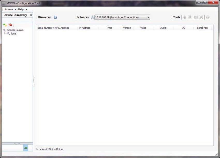
SECTION III                                   THEORY OF OPERATION
General:
This manual provides information expected to be used in installing, adjusting, and operating the EXO HD GeminEye™ System.

OVERVIEW
The EXO GeminEye system is fundamentally different than previous GeminEye models in that it provides streaming video and control through an IP connection. Unlike
previous models, there is no serial communication method, and there are no analog video outputs.

Each camera housing has a video server, also known as an encoder, which converts the video directly from the camera to streaming internet video. The two RJ45 IP con-
nectors on the cable are connected directly to the encoder, and provide the pathway for both video and control. The video for the visible camera is on the cable labeled
"Camera 1", and the video for the thermal camera (if equipped) is on "Camera 2". Both encoders in a two camera GeminEye have a separate control signal path to control
and position the GeminEye, and either encoder can control and position the unit.

The center section camera positioning system consists of stepper motors with their respective motor drivers controlled by a power supply and logic circuit boards. The unit
is powered by 10 to 30 VDC. Control communication from the encoders is processed on the logic circuit board, providing control and status information on the command
signal. Also connected to the control board are two positions sensing optical boards (one for the pan axis of motion, and one for tilt); these are referenced during a power
up condition to determine position of the system. During the power up cycle, the GeminEye will move to determine its position, and once the sensors are read, the unit will
return to the centered position.

LOGIC CONTROL BOARD
The logic control board is located inside the pan & tilt cabinet in the front heat sink. The control board processes all communication, and position information.

OPTO POSITION DETECTORS
There are 2 detection circuits used for detecting position and dynamic re-calibration. The pan uses a 4 channel optical system to read absolute sector position (16 sectors
of 22.5 degrees) and 17 transition points of pan movement. These are encoded using reflected binary code for absolute sector position. The tilt uses a 2 channel optical
system to read absolute sector position (4 sectors of 45 degrees) and 3 transition points. The positioner recalibrates "on the fly" when moving "right" and "down" directions.

The system counts motor pulses to the stepper motors to define position. Each micro step is equal to 0.01 degrees of movement in both the pan and tilt axis. These are
readout in 0.01º increments. If for any reason, the system is stalled during motion; the microcontroller will know what sector the system is in and will recalibrate the system
if sufficiently out of calibration.

DRIVE SYSTEM
The drive system consists of:
           • Two 0.9º stepper motors, each driven by a 16x micro step motor driver.
           • A high torque timing belt drive system with a 5.625:1 mechanical reduction ratio
           • The motor drivers generate a holding current which holds the motors in position when they are not being commanded to move.
           • The dual camera system uses 3 ball bearings, 3 thrust bearings, 3 rotary seals, 2 timing belts, and drive pulleys.
           • The stepper motor drive circuits divide each 0.9º step of the motor into 16 microsteps, providing for very fine motion control, with each microstep equating
              to 0.01 degree of movement. The QuickShift® technology introduces an additional division of speed, changing the speed range for pan and tilt independently.
              This allows a very wide dynamic range of speeds from fast to extremely slow movements.

COMMUNICATIONS & CONTROL BOARD
All communication to the EXO GeminEye model is through a Moog Video encoder, which is an IP connection only. There is one video encoder for each camera module, and
either can provide motion control of the positioner.

MN00178                                                                                                                                                                    1359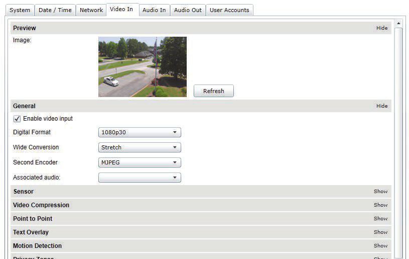
SECTION IV		                                  TEST SOFTWARE
SOFTWARE SETUP

Moog Configuration Tool
By factory default, the Moog EXO Camera is configured in DHCP. If you are not using a DHCP server it will automatically allocate itself an APIPA (Automatic Private IP Ad-
dressing) address in the range 169.254.0.1 to 169.254.255.254 with subnet mask 255.255.0.0.

Initial device network configuration is done via the Moog Discovery Tool (MDT), a tool provided by Moog that can be found on the company’s web site and on the CD-ROM
or flash drive supplied with each camera system. The flash drive also contains a copy of Microsoft Silverlight 5. Both programs should be installed on the local server.

The MDT plays 3 important roles:

1.         Discovery of all Moog EXO Cameras
2.         Allows for remote configuration of the IP address and subnet mask
3.         Permits batch firmware upgrade of all common EXO devices

Note: Silverlight is a free plug in and is required to interface with the Moog EXO Web brower. Once your device is installed on your network and powered up, launch MDT
from any computer on the network and the following window will be displayed:

The MDT supports 2 ways to discover a device. The first way doesn’t need any configuration and uses the Bonjour discovery protocol. In order to be able to discover a device
via Bonjour, the network must support multicast delivery.

If it is not the case, you can use the second way, which is the Unicast Discovery. The Unicast Discovery can be configured by using the “Unicast Discovery” configuration
form. This configuration form is available via the Admin / Unicast Discovery menu option.

By factory default, the Moog EXO GeminEye™ system is configured in DHCP. If you are not using a DHCP server it will automatically allocate itself an APIPA (Automatic
Private IP Addressing) address in the range 169.254.0.1 to 169.254.255.254 with subnet mask 255.255.0.0.

Initial device network configuration is done via the Moog Configuration Tool (MCT), a tool provided by Moog supplied on a CD-ROM that accompanied the product with each
GeminEye system, and that can be found on the company’s web site.

The MCT plays 3 important roles:

1.         Discovery of all Moog EXO GeminEye systems and EXO Cameras
2.         Allows for remote configuration of the IP address and subnet mask
3.         Permits batch firmware upgrade of all common EXO devices

Once your device is installed on your network and powered up, launch MCT from any computer on the network and the following window will be displayed:

The MCT supports 2 ways to discover a
device. The first way doesn’t need any
configuration and uses the Bonjour
discovery protocol. In order to be able to
discover a device via Bonjour, the network
must support multicast delivery.

If it is not the case, you can use the
second way, which is the Unicast
Discovery. The Unicast Discovery can be
configured by using the “Unicast Discovery”
configuration form. This configuration form
is available via the Admin / Unicast
Discovery menu option.

MN00178                                                                                                                                                                 1359
To configure the Unicast Discovery, add one or more IP address ranges. The Unicast Discovery tries to reach a device at a specific IP address in the configured ranges. The
discovery can be a long process if the range of IP addresses is large and the device is at the end of the range. To accelerate the discovery, add several small ranges of IP
addresses. The ping timeout option can be increased for a high latency network.

The MCT will display as many devices as it discovers on the network

If no DHCP server was able to assign an IP address to a Moog EXO Camera, it will appear in the MCT device list with an APIPA address (169.254.*.*). If a Moog Camera
displays an APIPA address it must be configured with a valid IP address before it can be remotely configured by selection the "Assign IP address" from the selection list
and configuring the TCP/IP settings.

MN00178                                                                                                                                                                 1359
To assign IP Address, update firmware, or configure Moog web interface, right click on highlighted serial number / Mac Address.

Assign IP address(es)
Once the IP information is set, the Silverlight web application served by the EXO Camera can be launched from the MDT or directly in your web browser by typing the device’s
IP address in the address bar. You can start to use your networked video management system for final system configuration or you can configure advanced parameters
using the Moog EXO web based management.

MN00178                                                                                                                                                                 1359
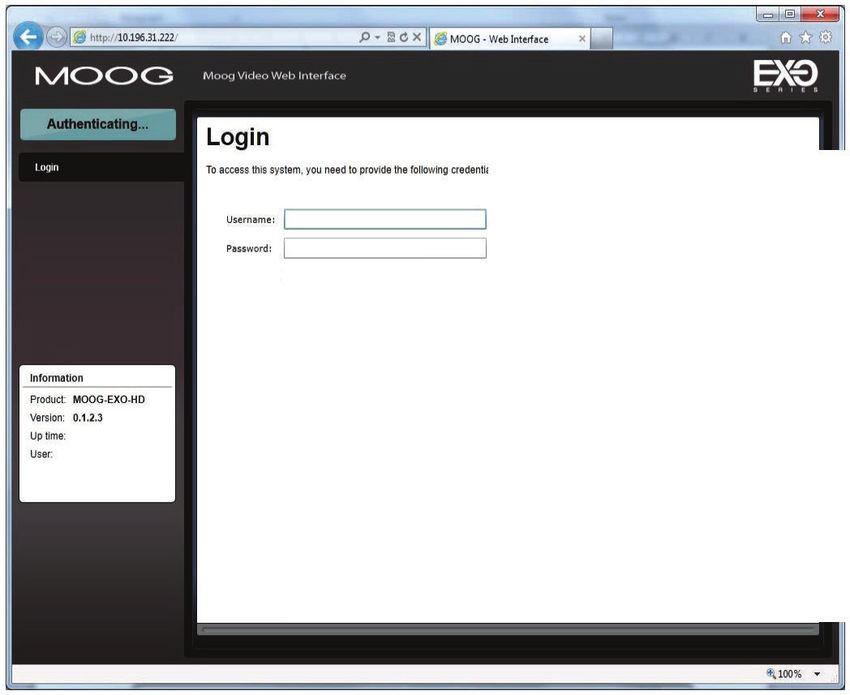
Using the Moog EXO Web Application

Application
When entering the Web Application, the following window will be displayed. You will be asked a username and password. The default User name and Password is 'admin'.
(To reset the user name and password see I Configurations I User Accounts)

MN00178                                                                                                                                                          1359
System Status

                                                                                Status Window

                                                                                                                     1.         System Status         - 2.1.0
                                                                                                                     2.         Configuration         - 2.2.0
                                                                                                                     3.         Maintenance           - 3.0.0
                                                                                                                     4.         Live Viewer           - 4.0.0
                                                                                                                     5.         Recording		           - 5.0.0
                                                                                Main Menu Tabs

Upon successfully logging into the web interface, a welcome screen will be displayed. The welcome screen shows general devices health status as well as firmware version
and system uptime.

MN00178                                                                                                                                                             1359
Configuration
Under the Configuration section, select the System tab to perform the following operations:
• View product model information, current firmware version and serial number.
• Specify a custom name; this name can be used by third-party software to display a selected name for the device.
Configuration / Date Time
Under the Configuration section, select the Date Time tab to perform the following operations:
• Set the time zone in which the device is operating.
• Manually set the current date and time for the device’s internal clock.
• Note: For an accurate time stamp, you must sync UTC Time.
MN00178 1359Configuration Network
Configuration / Network / DHCP
Under the Configuration section, select the Network tab to perform the following operations:
• Set the encoder’s IP parameters; DHCP or static IP information.
• Configure an NTP server to allow the device to automatically update its internal clock using an NTP server.
Configuration / Network / Host Name Configuration-NPT
NPT Server- use when desiring to have local network time as default, to do so you must…….
Configuration / Network / HTTP
• Change the device’s HTTP configuration, Note: Avoid changing these settings unless absolutely necessary.
MN00178 1359Configuration / Network / API- Boujour
NOTE:
To control the EXO Camera system with a VMS software system, you must enable the required Network APIs. Enable PSIA or GENETEC API depending on which VMS
platform you intend to use with the device. Disabling any unrequired APIs will accelerate boot time. Milestone VMS will link through the PSIA API.
• Note: ONVIF is standard built in and does not require activation. If using ONVIF you do not need to select an API.
• Set Bonjour discovery protocol settings.
• Modify SNMP settings to match with any SNMP software you wish to use for monitoring the device.
Configuration / Network / SNMP Configuration
Configuration / Network / RTSP Configuration
Configuration / Network / Multicast
If using Multicast output, Insert Multicast starts IP, and select start port.
MN00178 1359Configuration / Video In / Video Input Under the Configuration section, select the Video In tab to perform the following operations: Digital format – choices are, 720 30fps, 720 60fps, 1080 30fps, 1080 25fps. Note max camera output with WDR Active is 15fps (1080p). Configuration / Video In / Sensor Configure camera bloc / sensor parameters. These parameters will also be saved to the camera bloc itself if possible (Note: Activating WDR at 1080P will reduce maximum frame rate to 15fps.) Configure video compression parameters for any of the three available codec instances (Primary H.264, Secondary H.264 and MJPEG). Most VMS software solutions will interact with these parameters and thus it is suggested to leave these at default values in the web interface. VBR aggressiveness however is unique to Moog EXO Cameras and proposes various levels (disabled to aggressive) of motion triggered rate control. The more aggressive the setting, the more variation motion will have on the rate control. It is strongly suggested to disable VBR aggressiveness for low bit rate scenarios (below 1Mbps) as this parameter may negatively affect perceived video quality. MN00178 1359
Configuration / Video In / Video Compression

Set Quantization (QP) level to desired rate. The higher the number the greater the compression. (16 very low, 51 very high)

Frame Rate            - Allows you to specify the frame rate to be used by the codec.
Rate Control          - Allows you to choose between Variable Bit Rate and Constant Bit Rate. The first option will instruct the H.264 codec to dynamically adjust the
		                      bit rate in order to meet both the target quality (QP) and frame rate settings. The second option will instruct the H.264 codec to prioritize target
		                      bit rate and vary quality (QP) first and frame rate as a last resort

Min/Max QP            - This parameter allows you to specify the compression range that the codec will use to determine image quality during compression. In order to
		                      force a specific quality setting, you can set the minimum and maximum to the same value. The lower the value, the better the quality will be.

VBR Aggressiveness - This parameter allows you to specify if the codec should take into account the level of motion in the image for bit rate calculations. You can
		                   select from Conservative, Moderate and Aggressive options for this setting. Using the first option, the codec will allow bit rate to drop up to ¾ of
		                   the configured target bit rate when no motion is detected in the image. Using the second option, the codec will allow bit rate to drop up to ½ of
		                   the configured target bit rate when no motion is detected in the image. Using the first option, the codec will allow bit rate to drop up to ¼ of the
		                   configured target bit rate when no motion is detected in the image. You can disable this feature by selecting the disabled option.

Configuration / Video In / Point to Point

           • Configure point to point video connections (up to three) for creating persistent video streams from the encoder to a network endpoint.

MN00178                                                                                                                                                                 1359
Configuration / Video In / Text Overlay
To insert a text overlay:
• There are (2) available strings (Text blocks). Select string.
• Select string Size.
• For string position click mouse inside string position box.
– Text bar will appear on video image.
– If you wish to relocate, simply click in desired position.
– Type desired text into String Text Box.
– Press Save Button.
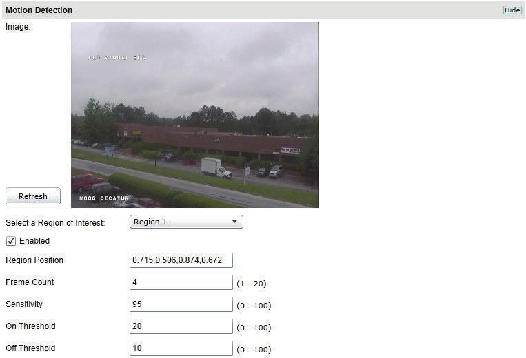
MN00178 1359Configuration / Video In / Motion Detection
Select from 1 of 4 available regions:
• With mouse click on region position box.
• Bring mouse pointer to view window and drag box around area for motion detection.
• Select desired Frame Count, Sensitivity and Thresholds.
• Press “Save” button to store information.
• You can select up to (4) separate “Motion” windows.
– Frame count: Number of frames required to trigger motion
– Sensitivity: No sensitivity, 100 MAX sensitivity
– Threshold: % of image required to trigger, both threshold must have a value; “off” value must be lower than “on”.
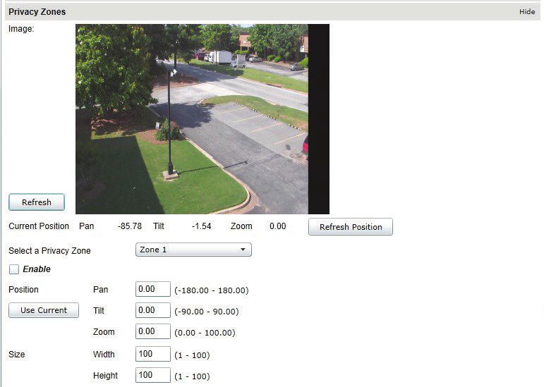
Configuration / Video In / Text Overlay
Privacy Zones are used to block out video in areas view is not permitted or desired.
MN00178 1359Configuration / Audio Out
Under the Configuration section, select the Audio Out tab to perform the following operations:
• Configure audio output parameters.
• Configure a point to point audio connection for receiving a persistent audio stream from a network endpoint.
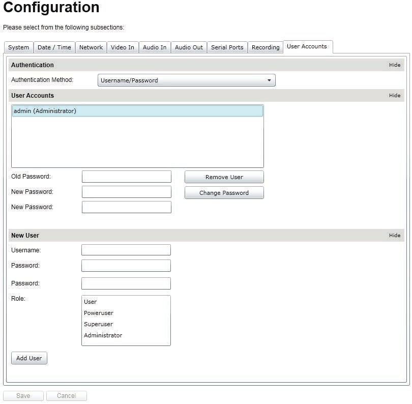
MN00178 1359Configuration / User Accounts
Under the Configuration section, select the User Accounts tab to perform the following operations:
• Select the web interface’s authentication method. A dual passphrase is made available for additional security.
• Manage user accounts which have access to the device.
User Roles:
Administrator: All is available
Super user: All is available except the user management
Power user: All is available except the user management and the recording
User: Only access basic operations: system information, live video (no PTZ controls), date time management and password change.
MN00178 1359Maintenance
This section describes how to update your Moog EXO Cameras to newer firmware versions from the web application.
1. Navigate to your device’s web application using your favorite web browser.
2. Click on the Maintenance tab.
3. Click on the Update button. You will be asked for the firmware update file; please select the .iof file which was provided by Moog.
4. You will see the following messages indicating the status of the update:
• Firmware upload in progress... (100%)
– Lasts around 95 seconds.
• Firmware uploaded. Saving to internal storage... (0%)
– Lasts around 45 seconds.
• Validating and decompressing firmware... (0%)
– Lasts around 105 seconds.
• Firmware ready for installation. Rebooting device... (0%)
– Web page will disconnect from device until device has rebooted.
– You will be prompted for login once the device is up again.
– Lasts around 110 seconds.
• Testing firmware stability... (26%)
– Lasts 120 seconds.
• Firmware update complete. (100%)
MN00178 1359Live Viewer
Use Live View for:
• Live Camera View
• Start and Stop Recording
• Pan / Tilt and Camera Control
• Setting Presets
• Adjust View Scale
To enable live you must activate by pressing the “Play” button.
Play Button
To adjust viewing scale for 1024 x 768 monitor, press scale view
MN00178 1359Live Viewer Pan / Tilt and Presets
Pan / Tilt
Controls
Lens
Controls
Preset
Controls
• Pan Tilt Control; To operate Press Arrow in desired direction of movement.
• Use Pan / Tilt speed slider controls to vary Pan / Tilt speed control, to increase speed, slide control knob to (?)
• Lens Function use +/- buttons to update Iris, Zoom and Focus.
• Preset Functions.
– First Select Preset No.
– Then position Camera and lens to desired position o Press “Set” to save Preset.
– For additional presets, repeat process.
– To clear, select desired preset press “clear”
• To establish a home position – move the camera to desired position, press set home position – Pan Tilt will use this as default start up position.
MN00178 1359Performing Batch Firmware Update This section describes how to perform a batch update of multiple Moog EXO Camera devices to newer firmware versions from the MCT. The batch firmware update works by starting a firmware update session. Only one session at time is allowed and only 20 devices can be selected by session. From the MDT, select one or more devices of the same type. By using the right mouse button on the selected devices, choose the “Firmware Update” menu option. MN00178 1359
To start a firmware update session, choose the “.iof” file corresponding to the new firmware by clicking to the “Select File …” button. Once selected, click to
the “Start” button.

Once started, the “Firmware Update Session” window shows the progress of the firmware update. This window can be closed at any moment without losing the
current session.

If closed, the progress of the current session can be followed by reopening the “Firmware Update Session” window by clicking the   button from the “Tools” toolbar.

Once done, clear the current session from the “Firmware Update Session” window and restart a new session if needed.

MN00178                                                                                                                                                               1359
Point to Point Connections
Point-to-point connections between an Moog EXO Camera and an Decoder can be configured using the device’s web application.

In the Moog EXO web application, in the Configuration section, goes to the Video In tab. Scroll down all the way to the bottom of the configuration page. The last 3
sections are named Point to Point 1, 2 and 3.

Here’s a quick overview of the settings available for a connection:

           • Enabled: Indicates whether this connection is to be used.
           • Description: Free-form user description of the connection, not used by the device.
           • Encoder: Indicates which video feed is to be sent over the point-to-point connection. Possible values include «Primary H.264 » and «Secondary H.264».
             These values refer to the encoders configured in previous sections of the same web page.
           • Destination IP: Address where to send the video. This is usually the address of a Decoder. The destination can also be a multicast group address. DNS
             names are not yet supported, only IP addresses.
           • Destination Port: Network port where to send the video. This value must match the port value in the Decoder.

Once all the settings have been set, click on Save at the bottom of the page to apply them. The Moog EXO Camera then creates or updates the connection as needed.

Troubleshooting Guide

           • Device does not seem to boot-up
             – Verify that a 24VDC power supply is connected to the device.
           • Cannot discover the device or communicate via the network
             – Before the device can be discovered, the status LED must be lit GREEN as this indicates ready state of the device.
             – Make sure you have connected the device to your network.
             – Dynamic discovery of the Moog Camera requires multicast networking to be supported by your network and switch equipment. (Bonjour Protocol)

MN00178                                                                                                                                                                1359
You can also read