Design manual - AD evaporative coolers - Robur
←
→
Page content transcription
If your browser does not render page correctly, please read the page content below
Design manual

AD evaporative coolers
Revision: C
Code: D-MNL053EN

This Design manual has been drawn up and printed by Robur S.p.A.; whole or partial reproduction of this
Design manual is prohibited.
The original is filed at Robur S.p.A.
Any use of this Design manual other than for personal consultation must be previously authorised by Robur S.p.A.
The rights of those who have legitimately filed the registered trademarks contained within this publication are not
affected.
With the aim of continuously improving the quality of its products, Robur S.p.A. reserves the right to modify the
data and contents of this Design manual without prior notice.
Design manual                                                                                                                                                                       AD evaporative coolers

                                                                                      INDEX OF CONTENTS

1 Premise����������������������������������������������������������������������������������������� p. 4                      7 Choice of models and number of coolers
2 Cooling and ventilation������������������������������������������������� p. 4                                                to be installed����������������������������������������������������������������������� p. 10
       2.1           Microclimate within the room������������������������������������ p. 4                                          7.1        Available range�������������������������������������������������������������� p. 10
       2.2           Safety, health and productivity���������������������������������� p. 4                                         7.2        Sizing examples������������������������������������������������������������� p. 10
                                                                                                                                     7.3        Evaporative cooler installation��������������������������������� p. 10
3 The technical solution����������������������������������������������������� p. 4
                                                                                                                              8 Hydraulic and electrical systems������������������������ p. 11
       3.1           The result and the advantages����������������������������������� p. 5
       3.2           System operation������������������������������������������������������������ p. 5                              8.1        Hydraulic system����������������������������������������������������������� p. 11
       3.3           Performances of the system���������������������������������������� p. 5                                        8.2        Electrical system������������������������������������������������������������ p. 12

4 Air psychrometric chart������������������������������������������������� p. 6                                              9 Evaluation of the effective efficiency of
                                                                                                                                the coolers������������������������������������������������������������������������������� p. 12
5 The evaporative cooler�������������������������������������������������� p. 8                                                     9.1        Water consumption is synonymous with
       5.1           Evaporative cooler operation������������������������������������� p. 8                                                    efficiency�������������������������������������������������������������������������� p. 12
       5.2           Description of the automatic cleaning system                                                                    9.2        Evaporative packs crossing speed�������������������������� p. 13
                     ����������������������������������������������������������������������������������������������� p. 8
       5.3           Routine maintenance���������������������������������������������������� p. 9                            10 Control and regulation solutions����������������������� p. 13
                                                                                                                                     10.1       ECO basic remote control������������������������������������������ p. 13
6 Design of a cooling and ventilation system                                                                                         10.2       EVO advanced remote control��������������������������������� p. 14
       �������������������������������������������������������������������������������������������������������������� p. 9          10.3       OCDS010/OCDS011 centralised control��������������� p. 14
       6.1            Outdoor summer design conditions����������������������� p. 9                                                  10.4       Centralized control with router�������������������������������� p. 16
       6.2            Air diffusers installation height in the building                                                       11 Diffusion plenums������������������������������������������������������������ p. 18
                      ����������������������������������������������������������������������������������������������� p. 9
       6.3            Number of required air changes depending on                                                                    11.1       Dimensions��������������������������������������������������������������������� p. 18
                      the type of activity in the building������������������������� p. 10                                    12 Technical data and dimensions���������������������������� p. 19
       6.4            Exhaust air evacuation������������������������������������������������ p. 10                                  12.1       Technical data���������������������������������������������������������������� p. 19
                                                                                                                                     12.2       Dimensions��������������������������������������������������������������������� p. 20
                                                                                                                                     12.3       Installation examples��������������������������������������������������� p. 21

Cod.: D-MNL053EN                      Rev.: C
                                                                                                AD evaporative coolers
                                                                                                                                                                                      21MCLSDC023                       26/07/2021            3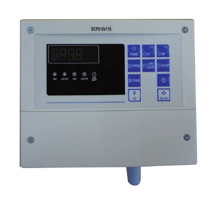
AD evaporative coolers

    1	PREMISE
    The purpose of this Design manual is to provide a first set of in-           cooling systems with Robur AD units.
    formation on the operation, design and characteristics of cool-              The Robur technical service is always at your disposal for any fur-
    ing systems with evaporative coolers Robur AD.                               ther technical information on the application and use of these
    Robur also provides a spreadsheet for a preliminary design of                appliances.

    2	COOLING AND VENTILATION
    The evaporative cooling system is the most modern technology                 Furthermore, during the night, when the room is closed, the
    for cooling and ventilation of large rooms:                                  heat stagnates inside the room, creating already in the morning
    ▶▶ production and crafts premises                                            conditions of poor comfort.
    ▶▶ commercial premises and warehouses                                        In addition to all this, there is usually a lack of proper air renewal
    ▶▶ sports premises in general                                                necessary for the disposal of exhaust air, sometimes harmful to
    This system allows you to equip even large rooms with summer                 the health of workers.
    ventilation and cooling system to improve the comfort of peo-
    ple, increase their well-being and productivity, without com-
                                                                                 2.2	SAFETY, HEALTH AND PRODUCTIVITY
    mitting large capital for plant expenses, without incurring high
    operating costs for energy consumption, without producing en-                The conditions of discomfort caused by high temperatures with-
    vironmental impact and without the risk of power blackouts for               in an industrial environment cause operators to experience the
    over-demand.                                                                 so-called "heat stress", which begins to be effective above 27 °C
                                                                                 causing:
                                                                                 ▶▶ Lowering of morale, delays and absenteeism
    2.1	MICROCLIMATE WITHIN THE ROOM
                                                                                 ▶▶ reduced attention to safety, increase in the percentage of
    Inside a large room, such as an industrial building, a microcli-                 injuries
    mate is established during the hot seasons that is difficult for the         ▶▶ potential health issues
    people who work there to endure.                                             ▶▶ reduced productivity, reduced production quality
    The heat input of process plants, electrical power plants and                Research has shown that this working condition adversely af-
    building structures which, when hit by the sun, transmit a high              fects productivity and production quality, as shown for example
    level of thermal energy to the internal air, often cause an unbear-          by a NASA report:
    able thermal condition in the environment.
    Table 2.1 NASA Report CR-1205-1
    Ambient temperature                               23 °C              26 °C      29 °C          32 °C              35 °C         37 °C          40 °C
    Loss in productivity                               3%                 8%        18%            29%                45%           62%            79%
    Loss in accuracy                                    -                 5%        40%            300%               700%            -              -

    Figure 2.1 NASA Report CR-1205-1
                           97% 92%                                                                                                          700%
               100%                                                                         700%
                                         82%
                80%                            71%
                                                                                            500%
                60%                                  55%                                                                            300%
            Y                                              38%                      Z       300%
                40%
                                                                  21%                       100%
                20%                                                                                                           40%
                                                                                                    0%           5%
                  0%                                                                         0%
                           23°C 26°C 29°C 32°C 35°C 37°C 40°C                                      23°C        26°C        29°C     32°C    35°C
                                               X                                                                              X
    X = internal temperature                          Y = productivity                                     Z = loss of accuracy

    NASA Report CR-1205-1 shows for example that when temper-                    18% and quality decreases by 40% due to increase in working
    atures inside the building rise over 29 °C, productivity drops by            errors.

    3	THE TECHNICAL SOLUTION
    To improve the summer microclimate inside a large room and                   hygiene, to dispose of any smells or hazardous gases and to im-
    reach an adequate level of well-being, the environment must be               prove productivity and safety of people.
    ventilated with cooled air and many new air changes must be                  A ventilation and cooling system with AD units consists of evap-
    granted to neutralize all heat supply.                                       orative coolers that cool the air with a natural principle and not
    The continuous renewal of the ambient air prevents the accu-                 through a refrigeration cycle.
    mulation of heat inside the building and prevents the excessive              The evaporative cooler is an appliance that cools the air by re-
    increase of the internal temperature.                                        ducing the sensible heat contained in it.
    The air renewal also allows to improve the level of environmental            The reduction of the sensible heat is due to the evaporation

4   Cod.: D-MNL053EN           Rev.: C
                                                              AD evaporative coolers
                                                                                                                              21MCLSDC023     26/07/2021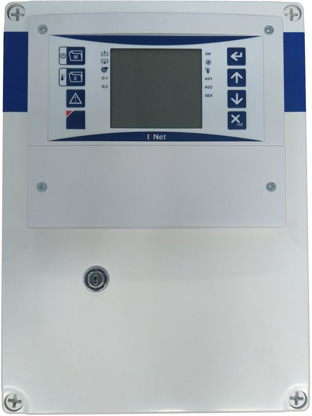
Design manual                                                                                                 AD evaporative coolers

process of the water that comes into contact with the treated air:        The operating principle is very simple: if the system expels all the
the air taken from the outside passes through cellulose panels            introduced air, the system produces maximum efficiency, grants
of particular structure wet with water, gives up part of its heat         all the planned air renewals and cools the environment under
during the process of evaporation of the water and lowers its             the design conditions.
temperature.                                                              It is also possible to have a slightly lower extract air flow than the
A fan, incorporated in the cooler, provides for the supply of the         supplied one (but not less than 80%), which allows the room to
cooled air into the room.                                                 be kept slightly overpressurised compared to the outside, pre-
                                                                          venting the outside hot air from re-entering the room through
                                                                          the natural openings.
3.1	THE RESULT AND THE ADVANTAGES
                                                                          The ideal condition is to place the air diffusers away from the
The absence of refrigerating units reduces by 70% the system              openings (windows, doors, etc.) and distribute them evenly in-
cost and by 80% the electrical energy consumption, which is               side the room. By opening a window away from the diffusers, the
reduced to that necessary for the fan operation, significantly re-        air passes through the room cooling it before being extracted.
duces the size of the systems and simplifies installation, opera-         By calculating the correct dimensions of the evacuation open-
tion and maintenance.                                                     ings the maximum efficiency of the system is reached. The sys-
In general, the advantages that can be obtained with this solu-           tem must be able to extract the large volume of air supplied so
tion are:                                                                 as not to reduce the effectiveness of the system.
▶▶ treatment of large volumes of air to achieve many hourly air           If the available openings are not sufficient, it is necessary to add
    renewals                                                              forced air extraction systems (extraction towers).
▶▶ air cooling                                                            Failure to comply with these conditions precludes the planned
▶▶ possibility of ventilation only in the less hot seasons                air renewal, reduces the cooling effect and increases the relative
▶▶ possibility of partial or differentiated management for differ-        humidity inside the room.
    ent areas of the room
▶▶ low cooling system costs, low running costs, low mainte-
                                                                          3.3	PERFORMANCES OF THE SYSTEM
    nance costs
▶▶ no use of environmentally harmful refrigerant gases (such as           The evaporative cooling system exploits the air adiabatic satura-
    CFC/HFC and greenhouse gases)                                         tion process: the unsaturated humid air is saturated by bringing
▶▶ improvement of hygiene in the room                                     it into very close contact with water, so that heat exchanges take
▶▶ increase of the productivity, quality and safety of internal           place only between air and water without other exchanges with
    staff                                                                 the outside.
                                                                          All the heat that the water receives from the air serves to evap-
                                                                          orate part of it, so the enthalpy of the residual water remains
3.2	SYSTEM OPERATION
                                                                          unchanged as well as its temperature. It follows that even the
                                                                          enthalpy of air does not change.
3.2.1	Ventilation and cleaning of the room                              The air temperature is therefore reduced, up to the maximum
The evaporative cooling system is a system that works dynami-             temperature of the water, while its humidity increases.
cally and works on the basis of a natural principle: it introduces        Since the enthalpy of the air is the sum of elements as a function
large quantities of cooled external air into the room and extracts        of temperature (sensible heat) and of an element as a function of
the exhausted hot air through doors, windows and other evacu-             humidity (latent heat), if its temperature decreases and the hu-
ation openings that are left open.                                        midity increases, it means that the sensible heat has decreased
                                                                          and the latent heat has increased (unchanged enthalpy). Of
Figure 3.1 Air flow in the room                                          course, the system increases its air cooling capacity as the rela-
                                                                          tive humidity of the outdoor air decreases: the drier the outside
                                                                          air is, the higher its possibility of saturation, the higher the re-
                                                                          duction of the sensible heat contained in it, therefore the greater
                                                                          the decrease of the obtainable air temperature.
                                                                          The cooling capacity of the air is also due to the technical char-
                                                                          acteristics of the exchange device (the evaporator) or to its satu-
                                                                          ration efficiency: in fact, the longer the time and surface contact
                                                                          between air and water, the more the water evaporates and the
                                                                          air temperature (sensible heat) decreases.
                                                                          The AD evaporative cooler is equipped with a high saturation
                                                                          efficiency evaporating unit which produces a good level of cool-
                                                                          ing even at relative air humidity values of around 70%.
                                                                          The temperature of the air supplied to the room is a function
                                                                          of the different conditions of the outside air, according to Table
                                                                          3.1 p. 5.
Table 3.1 Temperature of the air supplied to the room
  External temper-                                                 Relative humidity of the inlet air
       ature             20%               30%              40%                 50%                     60%        70%               80%
        25 °C            13,7              15,4             17,0                18,6                    20,0       21,3              22,6
        30 °C            17,0              19,1             21,0                22,8                    24,4       26,0              27,4
        35 °C            20,4              22,9             25,1                27,1                    29,0       30,6              32,1
        40 °C            23,0              26,0             29,0                31,5                    33,5       36,5              38,0

Cod.: D-MNL053EN       Rev.: C
                                                         AD evaporative coolers
                                                                                                               21MCLSDC023          26/07/2021     5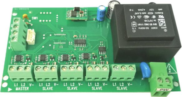
AD evaporative coolers

    4	AIR PSYCHROMETRIC CHART
    The performance of an evaporative cooling system varies ac-                    on the saturation efficiency of the evaporative pack and can be
    cording to the physical conditions of the treated air, they depend             obtained using air psychrometric chart.

    Figure 4.1 Air psychrometric chart - legend

                                                                                           1
                                                            7

                                                                                                 2

                                                                                                         3

                                                                                                                                        11
                                                                                                                                        12
                                                                                     6
                                                                                                   A                4

                                                   8
                                                        9                                          5

                                                                                      10
                                                            Tr         Tbu                    Ta
    1    Dry temperature                               6    Wet temperature                              11 Specific humidity
    2    Deviation of the enthalpy                     7    Enthalpy                                     12 Thermal factor
    3    Relative humidity                             8    Saturation curve                             Ta	Ambient temperature
    4    Specific humidity                             9    Pole                                         Tr	Dew temperature
    5    Specific volume                               10   Dry bulb temperature                         Tbu	Wet bulb temperature

6   Cod.: D-MNL053EN         Rev.: C
                                                            AD evaporative coolers
                                                                                                                      21MCLSDC023      26/07/2021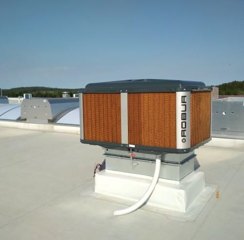
Design manual AD evaporative coolers
Figure 4.2 Air psychrometric chart
US [g/kg]
34
32
30
28
22
20
18
16
14
12
10
26
24
8
6
4
2
0
50
145
45
140
40
135
35
130
100
30
20
50
10
40
90 80 70 60
30
125
120
115
25
110
105
100
20
95
90
85
80
15
75
70
65
10
60
55
50
45
5
40
35
30
0
25
20
15
g]
-5
/k
kJ [
10
a
pi l
ta
En
5
0
-10
-5
-10
Tbs
It should therefore be specified that the evaporative cooling sys-
tem provides a different degree of comfort to the environment
as the physical conditions of the outdoor air change, and cannot
guarantee constant and predefined temperature and humidity
conditions.
Cod.: D-MNL053EN Rev.: C
AD evaporative coolers
21MCLSDC023 26/07/2021 7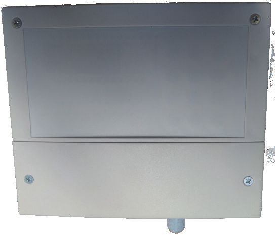
AD evaporative coolers
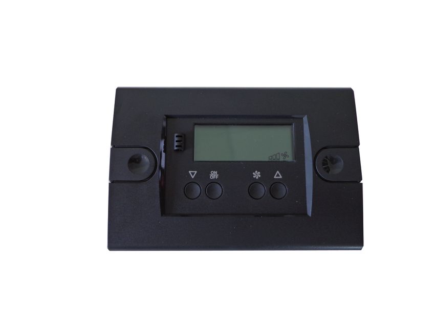
5 THE EVAPORATIVE COOLER
The AD evaporative cooler is an appliance powered by electricity There is an automatic washing cycle every 3 hours (standard):
and mains water, which is installed on the roof or on the exter- the appliance suspends its evaporation cycle for a few minutes,
nal wall or in correspondence with a window of the room to be the water contained in the tank is discharged and replaced with
ventilated and cooled. clean water that is circulated through the evaporative packs in
Ducts and air diffusers are connected to it to distribute the order to wash out the residues of mineral salts and any other
cooled air in the room. deposits.
The coolers are equipped with an external load-bearing struc- The repetitiveness of these washes prevents the crystallization
ture in ABS that guarantees protection from the weathering of minerals and other elements on the evaporative packs and
and a particular lightness, a very important aspect in relation to throughout the circuit, guarantees a long life and maintains a
the limited load-bearing capacity of the roofs and walls of the high saturation efficiency.
buildings. Each time the unit is switched off, a final wash cycle is performed.
The coolers are equipped with: At the end, the cooler discharges all the water contained in it
▶▶ low consumption electric fans to prevent water stagnation from causing the development of
▶▶ water loading system with solenoid valve bacterial forms and the formation of limescale deposits.
▶▶ water distribution system with electric pump
▶▶ evaporation panels with high saturation efficiency Figure 5.1 Cellulose evaporating panels
▶▶ automatic water drainage system
▶▶ automatic periodic cleaning for the whole hydraulic circuit
and the evaporating panels
▶▶ electronic control and operation panel
5.1 EVAPORATIVE COOLER OPERATION
Each cooler is equipped with a remote electronic control and
operation panel for adjusting the air speed and for choosing the
various functions:
▶▶ ventilation only
▶▶ ventilation and cooling
The panel contains the logic unit for setting the functions nec-
essary for the operation of the cooler, including the periodic
washing of the evaporating panels and the washing and the
drainage at the end of the cycle; these functions are essential for Figure 5.2 Recirculation pump and water distribution system
maintaining high performance over time and for preventing the
proliferation of bacterial forms.
Depending on the remote control chosen and used, it is also
possible to adjust the microclimate in each zone according to
the real needs of the time and season or according to the per-
sonal perception of the operator directly concerned, thanks to
the weekly and daily timer, to the maximum percentage of rela-
tive humidity required and to the fan speed.
▶▶ When the machine is started, the water discharge valve (nor-
mally open) closes, the water loading valve opens and allows
water to enter the collection tank. A level switch limits the
water load up to the amount required for the cooling cycle.
▶▶ An electric recirculation pump lifts the water up to the dis-
tributor circuit which wets the evaporating panels.
▶▶ The electric fan starts and sucks in the outside air through
the wet evaporating panels and feeds it into the room Figure 5.3 Automatic washing and emptying device
through the delivery outlet.
▶▶ The water that evaporates during the cycle is replenished on
command of the level switch of the collection tank.
▶▶ By acting on the control panel, it is possible to interrupt the
cooling function and operate the appliance in ventilation
mode only, granting in any case the required air renewal.
▶▶ By acting on the fan speed regulator it is possible to custom-
ize the flow and the quantity of air introduced into the room.
5.2 DESCRIPTION OF THE AUTOMATIC
CLEANING SYSTEM
The cooler is equipped with an automatic washing system for
the evaporative pack and the water collection tank which, at
programmable intervals, is automatically activated to maintain
a high level of cleanliness and saturation efficiency.
8 Cod.: D-MNL053EN Rev.: C
AD evaporative coolers
21MCLSDC023 26/07/2021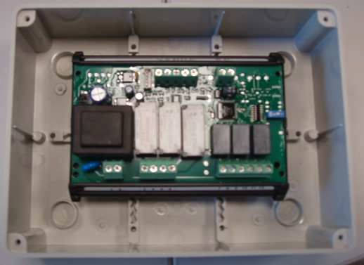
Design manual AD evaporative coolers
Figure 5.4 Water drain device 5.3 ROUTINE MAINTENANCE
Routine maintenance of the evaporative cooler is limited to end-
of-season cleaning, which includes washing the water distribu-
tion circuit, the evaporative packs, the recirculation pump and
the water collection tank.
In the winter season it is necessary to drain all the water con-
tained in the supply system to avoid damage caused by freezing.
The cooler can be covered with a winter cover (optional OCPR003
for AD14, optional OCPR004 for AD20) to protect it from weath-
ering and to prevent the intrusion of cold air into the room.
Every three to four years it is recommended to replace the evap-
orative packs.
6 DESIGN OF A COOLING AND VENTILATION SYSTEM
The purpose of the system is to cool and ventilate a large room dynamically and operates on the basis of a natural principle: it
during the hot seasons, lowering the temperature of the indoor introduces large quantities of external and cooled air into the
air compared to the outdoor air and making the necessary air room and expels the exhausted hot air through doors, windows
changes to improve the microclimate inside the room. and other exhaust openings.
The lowering of the internal temperature will help to neutralize The cooling of the air taken from the outside and introduced
the heat contributions coming from the structures of the build- into the room is a function of the outdoor conditions (Table
ing, from the sun's rays, from the process plants inside. 3.1 p. 5).
Air renewal will help to dispose of the exhausted air and any
fumes, vapours, smells or other aeriforms, often harmful to the
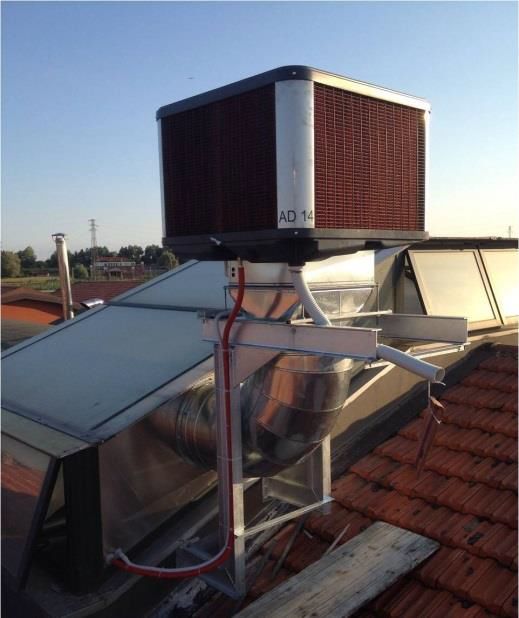
6.2 AIR DIFFUSERS INSTALLATION HEIGHT
health of workers.
The cooling efficiency is not only related to the efficiency of the
IN THE BUILDING
appliance, but also to the design of the ductwork and the instal- The air coming from the coolers tends to descend towards the
lation. Insulated ceilings will decrease the internal temperature floor and to push up the warmest one. The area of influence that
significantly compared to non-insulated ceilings. The same con- interests us is the one where people work, so the volume to be
cept is applicable for air ducting. cooled is that between the floor and the height of diffusion of
In order to size the plant we must take into account four funda- the cooled air.
mental elements: To allow normal operation, the air diffusers must be installed no
1. the outdoor summer design conditions less than 4 metres above the ground and, in order not to unnec-
2. the installation height of the air diffusers in the room essarily cool the upper part of the room, it is recommended not
3. the number of air changes required according to the type of to exceed 6 metres in height.
activity carried out in the room It should be noted that the higher the installation height of the
4. evacuation of exhaust air diffusers, the lower the cooling effect near the floor.
The volume to be treated is therefore equal to the surface area
6.1 OUTDOOR SUMMER DESIGN of the area concerned multiplied by the height from the ground
of the diffusers.
CONDITIONS
As already seen, the AD evaporative cooler is a system that works
Figure 6.1 Positioning of diffusers and extractors
Cod.: D-MNL053EN Rev.: C
AD evaporative coolers
21MCLSDC023 26/07/2021 9
AD evaporative coolers

     6.3	NUMBER OF REQUIRED AIR CHANGES                                    introduced (but not less than 80%) allows to keep the cooled
           DEPENDING ON THE TYPE OF ACTIVITY                                 room in a slight overpressure compared to the outside, prevent-
           IN THE BUILDING                                                   ing the outside hot air from re-entering the room through the
                                                                             natural openings.
     Once the volume to be cooled has been identified, it is necessary       The air produced by the coolers contains a percentage of relative
     to multiply it by the number of air renewals per hour required ac-      humidity higher than that of the external air and that of the air
     cording to the type of activity. The quantity of air to be supplied     in the building: this is precisely the characteristic that produces
     to the room is thus obtained to grant the required air renewal          the cooling effect. For this to be effective, however, it must pass
     and the cooling of the environment.                                     through the room and then leave. In this way, the percentage of
     Table 6.1 p. 10 indicates the minimum suggested air renewal             relative humidity in the room will not increase and the cooling
     for different activities.                                               effect will be granted.
     Table 6.1 Air renewal according to the activity                        To extract the exhaust air, natural openings of about 1 m2 per
                                                                             1000 m3 of air are required.
                         Activity                          Air renewal       If it is necessary to evacuate 10000 m3 of air it will take about 10
      Offices and shops                              v/h            8 ÷ 10   m2 of natural openings.
      Light processing (warehouses, storage areas)   v/h           10 ÷ 15   It is important that the openings (windows, doors, gates, sky-
      Medium processing (production and assembly                             lights, ...) are not concentrated in a single position or only on one
                                                     v/h          15 ÷ 20
      areas)
      Heavy processing (presence of ovens, equip-
                                                                             side of the room, but that they are distributed throughout the
                                                     v/h          20 ÷ 30    building to allow ventilation and cooling of the whole room and
      ments with moderate heat development)
      Extreme conditions (foundries, furnaces with                           not only of a part of it.
                                                     v/h          30 ÷ 40
      high heat generation)                                                  The best result is obtained when there are also openings on the
     v/h = volumes/hour.                                                     roof, such as skylights or natural extractors: through these open-
                                                                             ings it is possible to evacuate the mass of hot air that is under-
                                                                             neath the roof and usually stays there for a long time.
     6.4	EXHAUST AIR EVACUATION
                                                                                     If the natural openings are larger than the amount re-
     Once the quantity of air to be supplied to the room has been                    quired to evacuate the exhausted air, or if the extracted
     identified, the size of the openings required for exhaust air ex-               air flow rate is greater than 80% of the supplied air, there
     traction must be calculated.                                                    is a risk of attracting more hot air from outside and re-
     The system involves the introduction of cooled air into the room                ducing the cooling effect.
     and the extraction of at least 80% of it through natural openings
     or forced extraction systems.                                           If there are already forced extraction systems in operation in the
     The extraction of at least 80% of the air introduced is essential       room, their capacity must be taken into account and subtracted
     to grant the planned renewals, to grant the cooling effect and to       from the calculation of the necessary openings.
     avoid an increase in the percentage of relative humidity in the         It is necessary to ensure that there is a correct balance between
     room.                                                                   the amount of air entering and leaving the room.
     The extraction of a quantity of air slightly lower than the one

     7	CHOICE OF MODELS AND NUMBER OF COOLERS TO BE INSTALLED
     The choice of models and the number of AD coolers to be in-             of a maximum of 30 units, to be associated with a centralised
     stalled depends on the customer's needs, on the different possi-        control system, supplied by Robur.
     bilities of positioning the coolers and the air ducts, considering      The three versions can be summarized as follows:
     that the installation quota of the air diffusers should not exceed      ▶▶ AD14/AD20 ECO: equipped with the basic ECO remote con-
     6 m from the ground.                                                        trol (Paragraph 10.1 p. 13).
     The ideal choice is to install the coolers on the roof of the build-    ▶▶ AD14/AD20 EVO: equipped with the advanced EVO remote
     ing and enter with the ducts through the skylights.                         control (Paragraph 10.2 p. 14).
     The quantity of coolers to be installed depends on the calculat-        ▶▶ AD14/AD20 SC: without individual remote control, but de-
     ed intake air flow rate:                                                    signed for a centralised control (Paragraphs 10.3 p. 14 and
     Number of coolers = total air flow (m³/h) / air flow of the selected        10.4 p. 16).
     coolers (m³/h).
                                                                             7.2	SIZING EXAMPLES
               It is important to distribute the air in the room as evenly
               as possible.                                                  Surface area of building to be cooled: 2000 m²
                                                                             Building height: 8 m
                                                                             Height of the cooled air diffusers: 5 m
                                                                             Type of activity carried out inside: medium processing
     7.1	AVAILABLE RANGE                                                   Expected air changes: 15 v/h
     The AD evaporative coolers are available in two models, which           Net volume to be cooled: 2000 x 5 = 10000 m³
     differ in the maximum air flow that can be delivered:                   Total required air flow: 10000 x 15 = 150000 m³
     ▶▶ AD14 with air flow up to 13000 m³/h                                  Single cooler air flow rate: 20000 m³/h (model AD20)
     ▶▶ AD20 with air flow up to 20000 m³/h                                  Number of coolers to be provided: 150000/20000 = 8 AD20
     Three different versions are available for each model, two of
     which are equipped with an independent basic (ECO) or ad-               7.3	EVAPORATIVE COOLER INSTALLATION
     vanced (EVO) remote control for each unit, and the third (SC) is
     suitable for the centralised management of a system composed            The installation works are very simple and consist of clamping

10   Cod.: D-MNL053EN         Rev.: C
                                                               AD evaporative coolers
                                                                                                                  21MCLSDC023         26/07/2021
Design manual AD evaporative coolers
the machines in the chosen position, connecting the ducts and Figure 7.2 Installation example
air diffusers, the construction of the water supply and drainage
network and the power supply network and the connection of
the electronic control.
The following Figures show installation examples. 1
Figure 7.1 Installation example 2
≥ 0,4 m
6
3
1 4 7
6
2 8
≥1m
5
3
5 1 Skylight
2 Coverage
3 Stainless steel brackets
4 4 Duct with flanges and neoprene gaskets
5 6-way diffuser with adjustable louvres
1 Galvanized or stainless steel chains for fixing the ducts to the ceiling 6 Dowels to secure the brackets to the ceiling
2 Duct with flanges and neoprene gaskets 7 Screws to secure the duct to the brackets
3 2-way diffuser with adjustable louvres 8 Galvanized or stainless steel chains for fixing the ducts to the ceiling
4 Wall
5 90° curve with flanges and neoprene gaskets
6 Support frame
Figure 7.3 Installation example
1
5
2
3
6
4
1 Support frame
2 Duct with flanges and neoprene gaskets
3 Galvanized or stainless steel chains for fixing the ducts to the ceiling
4 6-way diffuser with adjustable louvres
5 45° curve with flanges and neoprene gaskets
6 Duct with flanges and neoprene gaskets
8 HYDRAULIC AND ELECTRICAL SYSTEMS
8.1 HYDRAULIC SYSTEM The distribution network must be equipped with a suitable filter
to prevent the passage of solid elements, such as sand and dirt.
The water necessary for the cooler operation can be drawn di-
rectly from the local water mains. The water supply system must grant a minimum flow
It is recommended to use drinking water, of hardness not ex- rate of 7 l/min for each unit at a pressure of 1,5÷3 bar
ceeding 27 °f and not less than 7 °f.
Do not use demineralised water, as it is potentially aggressive
towards some materials in the appliance.
Cod.: D-MNL053EN Rev.: C
AD evaporative coolers
21MCLSDC023 26/07/2021 11AD evaporative coolers
(maximum allowed pressure: 6 bar). It is recommended to provide for the possibility of emp-
tying the entire water supply system before the start of
the winter season to avoid damage due to freezing.
It is advisable to install the water supply network inside
the building to protect it from freezing in the winter The evaporative cooler is equipped with a sleeve located on the
season and from the sun's rays during the summer; oth- bottom of the external structure for the connection of the water
erwise, it is recommended to install a suitably insulated discharge pipe of the periodic washes.
pipe. Refer to Table 12.1 p. 19 for water connection dimensions and
water consumption.
The AD evaporative cooler is equipped with a water supply con-
nection located in the lower part of the external structure (detail 8.2 ELECTRICAL SYSTEM
A Figure 12.1 p. 20 and 12.2 p. 20).
It is recommended to install an isolation valve at the inlet of the The supply voltage of AD appliances is 230 V - 50 Hz.
unit and make the connection to the water supply with a flexible The electrical system must be constructed according to the reg-
stainless steel pipe. ulations in force in the country where the machine is installed.
Figure 8.1 Electrical wiring diagram
V+ L1 L2 V- M/S
1 1 Onboard electrical panel
2 Power supply 230 V - 50 Hz
X 3 Remote control
4 20 AWG 5x0,5 mm2 shielded cable
A1 5 Do not connect
A1 Main switch onboard the appliance
BRO Brown
WHI White
3 GRE Green
YEL Yellow
GRY Grey
2
GRE
GRY
BRO
WHI
YEL
A3
V- L2 L1 V+
MAX 25 m
5
4
The cooler must be connected to the selected remote control plus braid, 20 or 22 AWG, nominal capacitance between conduc-
(Paragraph 10 p. 13), which is normally installed in the cooled tors 89 pF, nominal capacitance between conductor and braid
room. 161 pF or an equivalent cable for RS485 networks with the fol-
To connect the remote control use a shielded cable 20 AWG lowing characteristics:
5x0,5 mm2 with a maximum length of 25 meters. 20 or 22 AWG
When using the OCDS010/OCDS011 centralised control twisted copper conductors
(Paragraph 10.3 p. 14) or the ODSP035 router (Paragraph characteristic impedance 120 Ω
10.4 p. 16) the network connection must be made using a braided shield
shielded cable capable of ensuring double insulation to live The maximum network length is 1000 m and 30 network cards
parts, with a minimum cross-section of 0,5 mm². We recommend connected to the centralised control, or 150 m per section and 4
the use of Belden cable model 8762 with PVC sheath, 2 poles coolers connected to the ODSP035 router.
9 EVALUATION OF THE EFFECTIVE EFFICIENCY OF THE COOLERS
9.1 WATER CONSUMPTION IS SYNONYMOUS Using the parameters of Table 9.1 p. 13 we can estimate that
WITH EFFICIENCY for every liter of water evaporated from 1000 m³ of air, there will
be a reduction in air temperature of about 2 ° C.
These appliances base their operating principle on the ability to
evaporate water using the heat contained in the air treated by
the cooler. In other words, the higher the water consumption,
the greater the cooling effect.
12 Cod.: D-MNL053EN Rev.: C
AD evaporative coolers
21MCLSDC023 26/07/2021Design manual AD evaporative coolers
Table 9.1 Air and water parameters Figure 9.1 Evaporative pack saturation efficiency diagram
Latent water evaporation heat J/kg 2260000 100
Water density kg/m³ 997
D=15
Air specific heat J/kg @40 °C 1005,5 0m
m
Air density kg/m³ 1,14
90
In the case of an AD14 cooler we have: 100
▶▶ air flow: 13000 m³/h
▶▶ water consumption: 43 l/h A
▶▶ temperature gradient of the outlet air: 6,5 °C 80
In general, if you want to make a comparison with other types 75
of coolers, the lower the declared water consumption, the lower
the cooling effect that can be obtained.
70
9.2 EVAPORATIVE PACKS CROSSING SPEED
The crossing speed of the evaporative packs of the treated air 50
also contributes to the efficiency of the appliance as a whole. 60
In fact, the producers of the exchange packs usually provide a 0.5 1 2 3 4 5
graph in which it is possible to deduce the exchange efficiency B
in relation to the air speed (and therefore the air flow rate of the
cooler): the higher the speed, the lower the exchange efficiency A Saturation efficiency (%)
(Figure 9.1 p. 13). B Air speed (m/s)
The grey area shows the conditions in which condensation forms.
Moreover, if the crossing speed approaches 3 m/s, the droplets
of water present on the edge of the evaporative packs may be
subject to entrainment, with the consequent introduction of wa-
ter into the cooled room.
In the case of an AD14 cooler we have:
▶▶ Net exchange area: 2,7 m²
▶▶ air flow: 13000 m³/h
▶▶ speed: 1,33 m/s
The crossing speed designed for the Robur AD units allows a
good exchange efficiency of the evaporative pack and a suffi-
ciently low speed to avoid dragging phenomena of water drop-
lets in the cooling air.
10 CONTROL AND REGULATION SOLUTIONS
The evaporative coolers are available in three different versions, 10.1 ECO BASIC REMOTE CONTROL
two of which are equipped with an independent basic (ECO) or
advanced (EVO) remote control for each unit, and the third (SC)
Figure 10.1 ECO basic remote control
suitable for the centralised management of a system composed
of up to 30 units, to be associated with a centralised control sys-
tem, supplied by Robur.
The three versions can be summarized as follows:
▶▶ AD14/AD20 ECO: equipped with the basic ECO remote con-
trol (Paragraph 10.1 p. 13).
▶▶ AD14/AD20 EVO: equipped with the advanced EVO remote
control (Paragraph 10.2 p. 14).
▶▶ AD14/AD20 SC: without individual remote control, but de-
signed for a centralised control (Paragraphs 10.3 p. 14 and
10.4 p. 16).
The ECO basic remote control is the basic control system for AD
evaporative coolers.
The features of the ECO basic remote control are:
▶▶ Turning the appliance on and off.
▶▶ Cooling/ventilation selection.
▶▶ Ventilation speed selection (3 levels).
▶▶ Diagnostics of any faults.
All settings must be made manually, as there is no time pro-
gramming for this control.
Refer to Figure 8.1 p. 12 for the wiring diagram.
Cod.: D-MNL053EN Rev.: C
AD evaporative coolers
21MCLSDC023 26/07/2021 13AD evaporative coolers
Table 10.1 ECO control technical specifications
Enclosure plastic box, dimensions: 120x82x30 mm
Mounting on the wall
Data retention on EEPROM memory
Protection IP00
ambient temperature -10 ÷ 60 °C
Operating conditions storage temperature -20 ÷ 70 °C
Relative environment humidity 20 ÷ 80%, non condensing
Connections screw terminals for wires with a maximum section of 2,5 mm²
Display 4 digits display + 4 icons + LED
Serial communication 1 TTL serial iFS interface
10.2 EVO ADVANCED REMOTE CONTROL system for AD evaporative coolers, which includes a humidity
and temperature probe already installed and connected to the
control.
Figure 10.2 EVO advanced remote control
The features of the EVO advanced remote control are:
▶▶ Automatic/manual operation selection.
▶▶ Cooling/ventilation selection.
▶▶ Automatic or manual selection of the ventilation speed (3
levels).
▶▶ Room temperature detection by integrated thermostat.
▶▶ Ambient humidity detection by integrated humidistat.
▶▶ Automatic operation based on the setpoint.
▶▶ Daily programming of the operating time schedule.
▶▶ Diagnostics of any faults.
The EVO control can guarantee automatic regulation of the cool-
er, thanks to the temperature and humidity probe, being able to
adjust the fan speed accordingly on the 3 available levels. With
the EVO control, it is also possible to set a daily time program,
being able to set the cooling or fan-only mode.
The EVO advanced remote control is the advanced control Refer to Figure 8.1 p. 12 for the wiring diagram.
Table 10.2 EVO control technical specifications
Enclosure plastic box, dimensions: 180x150x65 mm plus humidity sensor
Mounting on the wall
Data retention on EEPROM memory
Protection IP54
ambient temperature -10 ÷ 60 °C
Operating conditions storage temperature -20 ÷ 70 °C
Relative environment humidity 20 ÷ 80%, non condensing
Connections screw terminals for wires with a maximum section of 2,5 mm²
Display 4 digits display + 10 icons + LED
Inputs digital temperature and humidity probe (0 ÷ 99 RH accuracy at 25 °C: ± 3% F.S.), already connected and wired
Serial communication 1 TTL serial iFS interface
10.3 OCDS010/OCDS011 CENTRALISED Figure 10.4 OCDS010/OCDS011 centralised control
CONTROL
Figure 10.3 OCDS009 network board
14 Cod.: D-MNL053EN Rev.: C
AD evaporative coolers
21MCLSDC023 26/07/2021Design manual AD evaporative coolers
The OCDS010/OCDS011 centralised control allows centralised ▶▶ Keyboard lock via key (supplied).
management of systems consisting of several SC version cooling Each cooler must be in SC version (without individual control)
units (up to a maximum of 30). and must be equipped with a network board (optional OCDS009,
The functions of the centralised control are: with temperature and humidity probe already mounted and
▶▶ Display and setting of date and time on network boards. connected to the board), which communicates with the central-
▶▶ Display of temperature and humidity measured by network ised control panel via SC bus (OCDS010) and possibly provides
boards. an additional Modbus interface (OCDS011).
▶▶ Display and change of temperature and relative humidity OCDS010 is the version of the centralised control that communi-
setpoints for each network board. cates exclusively via SC bus, suitable if the centralised control is
▶▶ Display and change network device parameters (network not connected to other external supervisory devices.
boards and coolers). OCDS011 is the version of the centralised control that communi-
▶▶ Switching on/off of each individual network board. cates with the network boards via SC bus, but has an additional
▶▶ Daily programming of the operating time schedule of the Modbus interface, suitable for connection to external supervi-
whole system. sion systems (e.g. a BMS).
▶▶ Selection of automatic/manual/off operation for each indi- Figure 10.5 p. 16 below shows the wiring diagram for con-
vidual cooler. necting the network cards to the control panel (OCDS010 or
▶▶ Cooling/fan-only/off selection for each individual cooler. OCDS011).
▶▶ Diagnostics of any faults.
Table 10.3 OCDS009 network board technical specifications
Power supply 230 V AC ± 10%
Consumption 5 VA
Enclosure plastic box, dimensions: 180x150x65 mm plus humidity sensor
Mounting on the wall
Data retention on EEPROM memory
Protection IP54
ambient temperature -10 ÷ 60 °C
Operating conditions storage temperature -20 ÷ 70 °C
Relative environment humidity 20 ÷ 80%, non condensing
Connections screw terminals for wires with a maximum section of 2,5 mm²
Inputs digital temperature and humidity probe (0 ÷ 99 RH accuracy at 25 °C: ± 3% F.S.), already connected and wired
Table 10.4 OCDS010/OCDS011 centralised control technical specifications
Power supply 230 V AC, protected by 1,6 A delayed fuse (T)
Operation field -50.0 ÷ 150.0 °C
Consumption 7 VA
Enclosure plastic box, dimensions 300x220x120 mm
Mounting on the wall
Data retention on EEPROM memory
Protection IP00
ambient temperature -10 ÷ 50 °C
Operating conditions storage temperature -20 ÷ 70 °C
Relative environment humidity 20 ÷ 80%, non condensing
Connections screw terminals for wires with a maximum section of 2,5 mm²
Display LCD display
Keyboard lock Keyboard lock via key (supplied)
Outputs ALARM SPST relay 3(1)A 250 V AC
1 RS485 serial port for SC bus. The maximum allowed length of the network connection is 1000 m
1 TTL serial iFS interface for keyboard lock, already connected and wired on display board
1 TTL serial iFS interface for expansion key. It allows:
Serial communication • device FW update
• quick parameter configuration (copy/paste)
only for OCDS011: 1 RS485 serial port for Modbus
Cod.: D-MNL053EN Rev.: C
AD evaporative coolers
21MCLSDC023 26/07/2021 15AD evaporative coolers
Figure 10.5 Connection of OCDS009 network boards to OCDS010/OCDS011 centralised control
230 Vac
1
L N
1
2
SW1
DISPLAY
LCD
PW
SW2
1234
KEYBOARD PROBE
F1 = 1,6 AT
RS485 rH/tA
ON
SC bus
+A -B S I1 O I2 L1 L2
F1
2
LAN
RJ10 11 12 TERMINAL
display
LCD CN LOGIC CN LOGIC AD
I
O
ALARM
RS485 230 Vac
SC bus L N
iFS
13 14 15 16 17 19 20 21 23 24
1
A B S 230 Vac 2
SW1
PW
SW2
1234
PROBE
RS485 rH/tA
ON
SC bus
+A -B S I1 O I2 L1 L2
3
LAN
TERMINAL
AD
4
1 OCDS010/OCDS011 centralised control 3 OCDS009 network board
2 OCDS009 network board 4 Possible next OCDS009 network board
10.4 CENTRALIZED CONTROL WITH ROUTER The purpose of the ODSP035 router is to replicate, on several AD
coolers, the commands from a single ECO/EVO control, which
normally controls only one AD.
Figure 10.6 ODSP035 router
The AD cooler used as master will be of the ECO or EVO type,
while the other AD coolers must be of the SC type, i.e. without
control.
The ODSP035 router can manage a maximum of 5 AD coolers,
divided between a master and 4 slaves.
16 Cod.: D-MNL053EN Rev.: C
AD evaporative coolers
21MCLSDC023 26/07/2021Design manual AD evaporative coolers
Figure 10.7 Connection diagram for ODSP035 router
A
ODSP035
< 25m
KE
YBOAR
D
V+
L1
L2 POWER
V- SUPPLY
230Vac
MASTER SLAVE SLAVE SLAVE SLAVE 50/60Hz
L1 L2 V- L1 L2 V- L1 L2 V- L1 L2 V- L1 L2 V- 1 2
PW < 150m
B
m ODSP036
50AD evaporative coolers
11 DIFFUSION PLENUMS
For a more homogeneous diffusion of the cooled air in the room, ▶▶ 4-way diffusion plenum for AD14
diffusion plenums are available as an option: ▶▶ 6-way diffusion plenum for AD20
11.1 DIMENSIONS
Figure 11.1 4-way plenum ODFF002 dimensions
660
630
600
Ø8
105 100
495
600
630
660
250
600
650
805
Figure 11.2 6-way plenum ODFF003 dimensions
80
1630.7
8.3
660
590 630
590
1185
100
30
600
450
350
250
Ø8 1532.1
18 Cod.: D-MNL053EN Rev.: C
AD evaporative coolers
21MCLSDC023 26/07/2021Design manual AD evaporative coolers
12 TECHNICAL DATA AND DIMENSIONS
12.1 TECHNICAL DATA
Table 12.1 Technical data
AD14 AD20
Installation data
at maximum speed m³/h 13000 20000
Air flow at average speed m³/h 9700 15000
at minimum speed m³/h 6500 10000
fan type - axial
maximum useful pressure head Pa 80
water consumption l/h 43 (1) 64 (1)
type - M
Water inlet
thread “ 3/8
type - M
Water drain
diameter (Ø) mm 60
surface m² 2,7 3,4
Humidifying panel thickness mm 100
saturation efficiency % 89 87
at maximum speed dB(A) 94,0 90,0
sound power Lw at average speed dB(A) 85,0 82,0
at minimum speed dB(A) 80,0 77,0
at maximum speed dB(A) 72,0 (2) 68,0 (2)
sound pressure Lp at 5 m at average speed dB(A) 63,0 (2) 60,0 (2)
at minimum speed dB(A) 58,0 (2) 55,0 (2)
width mm 1150 1650
depth mm 1150
Dimensions height mm 1050
width mm 600 1185
Air delivery outlet
height mm 600 590
weight kg 67 120
Weight
in operation kg 88 146
Electrical specifications
voltage V 230
Power supply type - single-phase
frequency Hz 50
Electrical power absorption nominal kW 1,10 1,90
maximum power consumption A 4,8 7,0
(1) Test conditions: outdoor temperature 33 °C, relative humidity 60%.
(2) Maximum sound pressure levels in free field, with directionality factor 2, obtained from the sound power level in compliance with standard EN ISO 9614.
Cod.: D-MNL053EN Rev.: C
AD evaporative coolers
21MCLSDC023 26/07/2021 19AD evaporative coolers
12.2 DIMENSIONS
Figure 12.1 AD14 dimensions
1150 1150
A Water inlet 3/8" M
B Water drain 60 mm M
C Electrical panel
1050
D D 86 A243
C A B C B
170
117
80
38 280 320 65 209
555 595
110 112 217
660
600 440
660
600
630
D-D
630
Figure 12.2 AD20 dimensions
1650 1150
1050
D D A
C
189
C A 261.5
B
128
150
B
130
80
530 195 165
592.5 592.5
205 170 85 280
825 825
530
1245
1185
590
660
620
D-D
1215
A Water inlet 3/8" M
B Water drain 60 mm M
C Electrical panel
20 Cod.: D-MNL053EN Rev.: C
AD evaporative coolers
21MCLSDC023 26/07/2021Design manual AD evaporative coolers
12.3 INSTALLATION EXAMPLES Figure 12.4 Installation example
Figure 12.3 Installation example
Figure 12.5 Installation example
Figure 12.6 Installation example
Cod.: D-MNL053EN Rev.: C
AD evaporative coolers
21MCLSDC023 26/07/2021 2126/07/2021
21MCLSDC023
Robur mission
Robur is dedicated to dynamic progression
in research, development and promotion
of safe, environmentally-friendly, energy-efficiency products,
Code: D-MNL053EN
through the commitment and caring
of its employees and partners.
Revision: C
Robur S.p.A.
advanced technologies
for air conditioning
via Parigi 4/6
24040 Verdellino/Zingonia (BG) Italy
+39 035 888111 - F +39 035 884165
www.robur.it robur@robur.itYou can also read