SID, SID SL 2021 - service manual - SRAM Service
←
→
Page content transcription
If your browser does not render page correctly, please read the page content below
2021
SID, SID SL

service manual

                 GEN.0000000006161 Rev A © 2020 SRAM, LLC
SRAM® LLC WARRANTY
EXTENT OF LIMITED WARRANTY
Except as otherwise set forth herein, SRAM warrants (i) Zipp® MOTO™ Rims to be free from defects in materials or workmanship for the lifetime of the
product, and (ii) its other products to be free from defects in materials or workmanship for a period of two years after original purchase. This warranty
only applies to the original owner and is not transferable. Claims under this warranty must be made through the retailer where the bicycle or the
SRAM component was purchased. Original proof of purchase is required. Except as described herein, SRAM makes no other warranties, guaranties, or
representations of any type (express or implied), and all warranties (including any implied warranties of reasonable care, merchantibility, or fitness for a
particular purpose) are hereby disclaimed.
LOCAL LAW
This warranty statement gives the customer specific legal rights. The customer may also have other rights which vary from state to state (USA), from
province to province (Canada), and from country to country elsewhere in the world.
To the extent that this warranty statement is inconsistent with the local law, this warranty shall be deemed modified to be consistent with such law,
under such local law, certain disclaimers and limitations of this warranty statement may apply to the customer. For example, some states in the United
States of America, as well as some governments outside of the United States (including provinces in Canada) may:
Preclude the disclaimers and limitations of this warranty statement from limiting the statutory rights of the consumer
(e.g. United Kingdom).
Otherwise restrict the ability of a manufacturer to enforce such disclaimers or limitations.
FOR AUSTRALIAN CUSTOMERS:
This SRAM limited warranty is provided in Australia by SRAM LLC, 1000 W. Fulton Market, 4th Floor, Chicago, IL, 60607, USA. To make a warranty claim
please contact the retailer from whom you purchased this SRAM product. Alternatively, you may make a claim by contacting SRAM Australia, 6 Marco
Court, Rowville 3178, Australia. For valid claims SRAM will, at its option, either repair or replace your SRAM product. Any expenses incurred in making
the warranty claim are your responsibility. The benefits given by this warranty are additional to other rights and remedies that you may have under
laws relating to our products. Our goods come with guarantees that cannot be excluded under the Australian Consumer Law. You are entitled to a
replacement or refund for a major failure and for compensation for any other reasonably foreseeable loss or damage. You are also entitled to have
the goods repaired or replaced if the goods fail to be of acceptable quality and the failure does not amount to a major failure.
LIMITATIONS OF LIABILITY
To the extent allowed by local law, except for the obligations specifically set forth in this warranty statement, in no event shall SRAM or its third party
suppliers be liable for direct, indirect, special, incidental, or consequential damages.
LIMITATIONS OF WARRANTY
This warranty does not apply to products that have been incorrectly installed, adjusted, and/or maintained according to the respective SRAM user
manual. The SRAM user manuals can be found online at sram.com, quarq.com, or zipp.com.
This warranty does not apply to damage to the product caused by a crash, impact, abuse of the product, non-compliance with manufacturers
specifications of usage or any other circumstances in which the product has been subjected to forces or loads beyond its design.
This warranty does not apply when the product has been modified, including, but not limited to any attempt to open or repair any electronic and
electronic related components, including the motor, controller, battery packs, wiring harnesses, switches, and chargers.
This warranty does not apply when the serial number or production code has been deliberately altered, defaced or removed.
SRAM components are designed for use only on bicycles that are pedal powered or pedal assisted (e-MTB/Pedelec).
To qualify for the warranty, Eagle Chain, Cassette, and Rear Derailleur must be used with a SRAM 1-Click™ shifter when used on e-MTB/Pedelec style
bicycles.
Zipp 3ZERO MOTO™ Rims and wheels comply with ASTM F2043-13 5.1.4, Conditions 1, 2, 3, and 4 for use of bicycle components on paved roads,
rough trails, rough unpaved roads, rough terrain and unimproved trails that require technical skills, and downhill grades on rough trails at speeds less
than 40 km/h (25 mph). Jumps are intended to be less than 122 cm (48 in.).
This warranty does not apply to damage to Zipp MOTO Rims outside of intended use (Trail/Enduro) situations or incurred in connection with Downhill/
Dual Crown bicycles.
All Zipp MOTO Rim warranty claims will be evaluated by a SRAM/Zipp Authorized Service Location.
This warranty does not apply to normal wear and tear. Wear and tear parts are subject to damage as a result of normal use, failure to service
according to SRAM recommendations and/or riding or installation in conditions or applications other than recommended.
WEAR AND TEAR PARTS ARE IDENTIFIED AS:
• Dust seals                         • Stripped threads/bolts (aluminium, • Handlebar grips                   • Transmission gears
• Bushings                             titanium, magnesium or steel)       • Shifter grips                    • Spokes
• Air sealing o-rings                • Brake sleeves                       • Jockey wheels                    • Free hubs
• Glide rings                        • Brake pads                          • Disc brake rotors                • Aero bar pads
• Rubber moving parts                • Chains                              • Wheel braking surfaces           • Corrosion
• Foam rings                         • Sprockets                           • Bottomout pads                   • Tools
• Rear shock mounting                • Cassettes                           • Bearings                         • Motors
  hardware and main seals            • Shifter and brake cables            • Bearing races                    • Batteries
• Upper tubes (stanchions)             (inner and outer)                   • Pawls                            • Driver Bodies
Notwithstanding anything else set forth herein, the battery pack and charger warranty does not include damage from power surges, use of improper
charger, improper maintenance, or such other misuse.
This warranty shall not cover damages caused by the use of parts of different manufacturers.
This warranty shall not cover damages caused by the use of parts that are not compatible, suitable and/or authorised by SRAM for use with SRAM
components.
This warranty shall not cover damages resulting from commercial (rental) use.
SAFETY FIRST!
We care about YOU. Please, always wear your safety glasses
and protective gloves when servicing RockShox® products.
          Protect yourself! Wear your safety gear!
TABLE OF CONTENTS
ROCKSHOX SERVICE...........................................................................................................................................................................................5
       PART PREPARATION .......................................................................................................................................................................................................................................5
       SERVICE PROCEDURES..................................................................................................................................................................................................................................5
       RECOMMENDED SERVICE INTERVALS.....................................................................................................................................................................................................6
       RECORD YOUR SETTINGS.............................................................................................................................................................................................................................6
       TORQUE VALUES..............................................................................................................................................................................................................................................6
       OIL VOLUME AND LUBRICANT.................................................................................................................................................................................................................... 7
       PARTS, TOOLS, AND SUPPLIES...................................................................................................................................................................................................................8

EXPLODED VIEW - SID SL ULTIMATE \ CHARGER RACE DAY DAMPER.....................................................................................................9

EXPLODED VIEW - SID ULTIMATE \ CHARGER RACE DAY DAMPER........................................................................................................10

EXPLODED VIEW - SID SL SELECT + \ CHARGER 2 DAMPER RL................................................................................................................11

EXPLODED VIEW - SID SELECT + \ CHARGER 2 DAMPER RL....................................................................................................................12

EXPLODED VIEW - SID SL SELECT \ CHARGER DAMPER RL..................................................................................................................... 13

EXPLODED VIEW - SID SELECT \ CHARGER DAMPER RL...........................................................................................................................14

LOWER LEG REMOVAL AND SERVICE............................................................................................................................................................15
                                                                                                         50/200 HOUR SERVICE
       LOWER LEG REMOVAL.................................................................................................................................................................................................................................. 15
                                                                                                             50 HOUR SERVICE
       LOWER LEG SERVICE.................................................................................................................................................................................................................................... 18
                                                                                                            200 HOUR SERVICE
       LOWER LEG SEAL SERVICE........................................................................................................................................................................................................................ 20

AIR SPRING SERVICE........................................................................................................................................................................................ 23
       TRAVEL CHANGE ADJUSTMENT - OPTIONAL.................................................................................................................................................................................... 23
       BOTTOMLESS TOKEN - OPTIONAL INSTALLATION.......................................................................................................................................................................... 23
                                                                                                            200 HOUR SERVICE
       DEBONAIR SPRING SERVICE..................................................................................................................................................................................................................... 24

CHARGER RACE DAY DAMPER SERVICE..................................................................................................................................................... 30
                                                                                                            200 HOUR SERVICE
       CHARGER RACE DAY DAMPER REMOVAL............................................................................................................................................................................................ 30
       BLEED PROCEDURE...................................................................................................................................................................................................................................... 32
       CHARGER RACE DAY DAMPER INSTALLATION...................................................................................................................................................................................37

CHARGER 2 DAMPER SERVICE...................................................................................................................................................................... 39
                                                                                                            200 HOUR SERVICE
       CHARGER 2 DAMPER REMOVAL.............................................................................................................................................................................................................. 39
       BLEED PROCEDURE...................................................................................................................................................................................................................................... 43
       TEST THE BLEED............................................................................................................................................................................................................................................ 46
       CHARGER 2 DAMPER INSTALLATION - CROWN..................................................................................................................................................................................47
       CHARGER 2 DAMPER INSTALLATION - REMOTE................................................................................................................................................................................ 48

CHARGER DAMPER RL SERVICE.................................................................................................................................................................... 49
                                                                                                            200 HOUR SERVICE
       DAMPER REMOVAL....................................................................................................................................................................................................................................... 49
       DAMPER SERVICE........................................................................................................................................................................................................................................... 51
       DAMPER ASSEMBLY..................................................................................................................................................................................................................................... 54
       TEST COMPRESSION.................................................................................................................................................................................................................................... 58
       DAMPER INSTALLATION.............................................................................................................................................................................................................................. 59

LOWER LEG ASSEMBLY..................................................................................................................................................................................... 61
                                                                                                         50/200 HOUR SERVICE
       LOWER LEG INSTALLATION........................................................................................................................................................................................................................ 61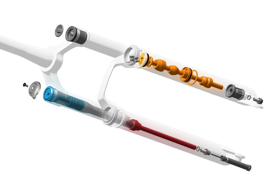
RockShox Service
We recommend that you have your RockShox suspension serviced by a qualified bicycle mechanic. Servicing RockShox suspension requires
knowledge of suspension components, as well as the use of specialized tools and lubricants/fluids. Failure to follow the procedures outlined in this
service manual may cause damage to your component and void the warranty.
Visit www.sram.com/service for the latest RockShox Spare Parts catalog and technical information. For order information, please contact your local
SRAM® distributor or dealer.
Information contained in this publication is subject to change at any time without prior notice.
Your product's appearance may differ from the pictures contained in this publication.
      For recycling and environmental compliance information, please visit www.sram.com/company/environment.

 Part Preparation
Remove the component from the bicycle before service.
Disconnect and remove the remote cable or hydraulic hose from the fork or rear shock, if applicable. For additional information about RockShox
remotes, user manuals are available at www.sram.com/service.
Clean the exterior of the product with mild soap and water to avoid contamination of internal sealing part surfaces.

 Service Procedures
The following procedures should be performed throughout service, unless otherwise specified.

Clean the part with RockShox Suspension Cleaner or isopropyl alcohol and
a clean, lint-free shop towel. For hard to reach places (e.g. upper tube, lower
leg), wrap a clean, lint-free shop towel around a non-metallic dowel to clean
the inside.
Clean the sealing surface on the part and inspect it for scratches.

Replace the o-ring or seal with a new one from the service kit. Use your
fingers or a pick to pierce and remove the old seal or o-ring.
Apply grease to the new seal or o-ring.

                                  NOTICE
 Do not scratch any sealing surfaces when servicing the product. Scratches
 can cause leaks. Consult the spare parts catalog to replace the damaged
 part.

Use aluminum soft jaws when placing a part in a bench vise.
Tighten the part with a torque wrench to the torque value listed in the red bar.
When using a crowfoot socket and torque wrench, install the crowfoot socket
at 90 degrees to the torque wrench.

                                                                                                                         Specified torque value in N·m (in-lb)

                                                                                                                                RockShox Service                 5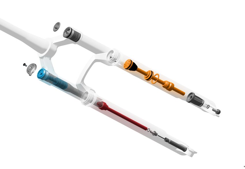
Recommended Service Intervals
Regular service is required to keep your RockShox product working at peak performance. Follow this maintenance schedule and install the service
parts included in each service kit that corresponds with the Service Hours Interval recommendation below. For spare part kit contents and details,
refer to the RockShox Spare Parts Catalog at www.sram.com/service.

 Service Hours Interval          Maintenance                               Benefit

                                                                           Extends wiper seal lifespan
                                 Clean dirt from upper tubes and
 Every ride                                                                Minimizes damage to upper tubes
                                 wiper seals.
                                                                           Minimizes lower leg contamination

                                                                           Restores small bump sensitivity

 Every 50 Hours                  Perform lower leg service                 Reduces friction

                                                                           Extends bushing lifespan

                                                                           Extends suspension lifespan

 Every 200 Hours                 Perform damper and spring service         Restores small bump sensitivity

                                                                           Restores damping performance

 R e c o r d Yo u r S e t t i n g s
Use the charts below to record your settings to return your fork to its pre-service settings. Record your service date to track
service intervals.

                                                                                                                   Charger Damper Only
                                                                           Rebound setting - count the
                                                                                                                   Low-speed Compression setting
 Service Hours                                                             number of clicks while turning the
                       Date of Service             Air Pressure                                                    - count the number of clicks while
 Interval                                                                  rebound adjuster fully counter-
                                                                                                                   turning the compression adjuster
                                                                           clockwise.
                                                                                                                   fully counter-clockwise.

 50

 100

 150

 200

 To r q u e Va l u e s
 Part                                                                      Tool                                    Torque
 Bottom bolts                                                              5 mm hex bit socket                     6.8 N·m (60 in-lb)

 Top caps                                                                  Top cap/cassette tool or 24 mm          28 N·m (250 in-lb)
                                                                           socket
 Bottomless Tokens                                                         8 mm hex wrench and 24 mm               4 N·m (35 in-lb)
                                                                           socket and/or Top Cap/Cassette
                                                                           tool
 Race Day Damper rebound nut                                               10 mm socket                            4 N.m ( 35 in-lb)

 Race Day Damper lockout adjuster knob retaining screw                     2 mm                                    0.3 Nm (3 in-lb)

 Race Day Damper cable stop collar screw                                   2 mm                                    0.3 Nm (3 in-lb)

 Race Day Damper spool retaining screw                                     1.5 or 2 mm                             0.3 Nm (3 in-lb)

 Charger 2 Damper RL /RL R* retaining screw                                2 mm hex bit socket                     1.4 N.m (12 in-lb)

 Charger 2 Damper RL R* cable stop collar bolt                             2 mm hex bit socket                     0.4 N.m (4 in-lb)

 Charger Damper RL retaining screw                                         2.5 mm hex bit socket                   1.4 N•m (12 in-lb)

* remote adjust

                                                                                                                  Recommended Service Intervals         6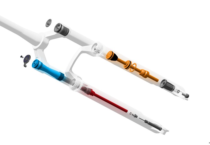
Oil Volume and Lubricant

                           Damper                                         Spring

                                      Upper Tube        Lower Leg                    Upper Tube                     Lower Leg

Fork   Model      Travel   Damper                                         Spring
                                      Oil      Volume   Oil      Volume              Oil      Volume                         Volume
                                                                                                        Grease      Oil
                                      Weight   (mL)     Weight   (mL)                Weight   (mL)                           (mL)

                            Charger
       Ultimate
                           Race Day

                   110-     Charger
SID    Select+
                   120       2 RL
                                                                                                        Apply
                            Charger                                                                     Rock-
        Select                                                                                          Shox
                              RL
                                                                                                        Dynamic
                                       3wt     Bleed    0w-30       10    DebonAir   0w-30        3                 0w-30         10
                                                                                                        Seal
                            Charger                                                                     Grease
       Ultimate
                           Race Day                                                                     to Air
                                                                                                        Piston
SID                         Charger
       Select+     100
SL                           2 RL

                            Charger
        Select
                              RL

                                                                                                       Oil Volume and Lubricant        7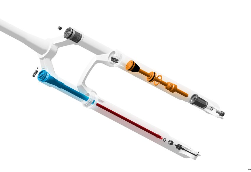
P a r t s , To o l s , a n d S u p p l i e s
Parts                                                                       Common Tools
• 2021 SID Service Kit - 200 hour                                           • Air compressor and nozzle
• 2021 SID SL Service Kit - 200 hour                                        • Bench vise and aluminum soft jaws
Safety and Protection Supplies                                              • Cable ties (Select +))
• Apron                                                                     • Crowfoot: 19 mm (Select/Select +)
• Clean, lint-free shop towels                                              • Downhill tire lever
• Nitrile gloves                                                            • Hex wrenches: 1.5, 2, 2.5, 5, 8 mm
• Oil pan                                                                   • Hex bit sockets: 1.5, 2, 2.5, and 5 mm
• Safety glasses                                                            • Internal retaining ring pliers- large
RockShox Tools                                                              • Long plastic or wooden dowel
• RockShox Bleed Syringe                                                    • Open end wrench: 19 mm (Select +)
• RockShox Charger vise blocks - 27.35mm (Select +)                         • Pick
• RockShox Top Cap/Cassette tool (3/8" / 24 mm)                             • Plastic or rubber mallet
• RockShox Dust Seal Installation Tool 32 mm (SID SL) or                    • Sockets: 7 (Select), 10 (Ultimate), 13 (Select+) and 24 mm
  35 mm (SID)                                                               • Socket extension (Ultimate)
• RockShox Shock Pump                                                       • Socket wrench
Lubricants and Fluids                                                       • T10 TORX wrench and bit socket
• Isopropyl alcohol or RockShox Suspension Cleaner                          • Torque wrench
• RockShox 0w-30 Suspension Oil
• Maxima PLUSH 3wt Suspension Oil (RL/RL R)
• Maxima PLUSH 7wt Suspension Oil (RL3/RLC3)
• RockShox Dynamic Seal Grease (PTFE)
Bicycle Tools
• Bicycle stand
• Downhill tire lever
• Shock pump

                                                       SAFETY INSTRUCTIONS
Always wear safety glasses and nitrile gloves when working with suspension oil and bicycle grease.
Place an oil pan on the floor underneath the area where you will be working on the fork.

                                                                                                                      Parts, Tools, and Supplies   8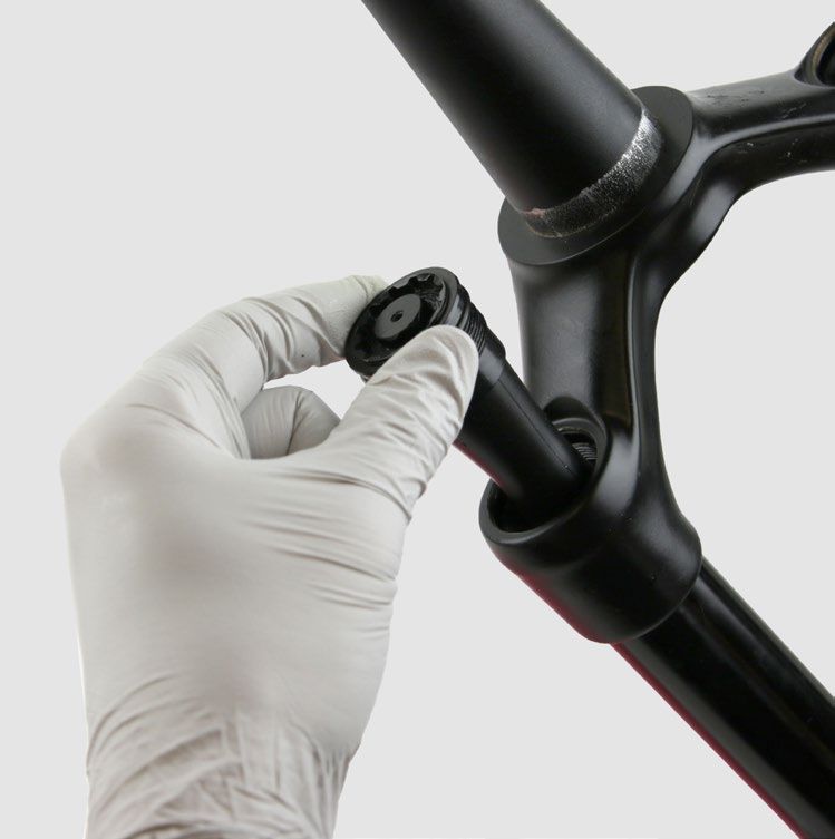
Exploded View - SID SL Ultimate \ Charger Race Day Damper

                                                                                                                             Air Spring Assembly

                                                                          Air valve cap                                      Compression Damper
                                                                                                                             Assembly

                                                                          Top cap                                            Rebound Damper
                                                                                                                             Assembly

                                                                        Bottomless Token(s)

                                                                          Upper tube
                            Lockout adjuster knob
                            and retaining screw
                            Top cap

                            Compression damper

                                         Lower leg

                                                     Brake hose guide

                                                                                                              Air piston

              Wiper seal                                                                                      Top out bumper cone

              Foam ring

                                                                                    Seal head

                                                                                 Retaining ring
              Rebound damper shaft
                                                                                                 Jounce
                                                                                              bottom out
                                                                                                 bumper

                                                                                                  Air shaft

 SID SL Ultimate R

                                                                                            Bottom cup
                           Spool and screw

                                                           Crush washer                                            Crush washer

                                                                                                                     Bottom bolt
Cable                                                      Rebound nut
stop collar
and screw
                                                       Rebound adjuster

                                                                                    Exploded View - SID SL Ultimate \ Charger Race Day Damper      9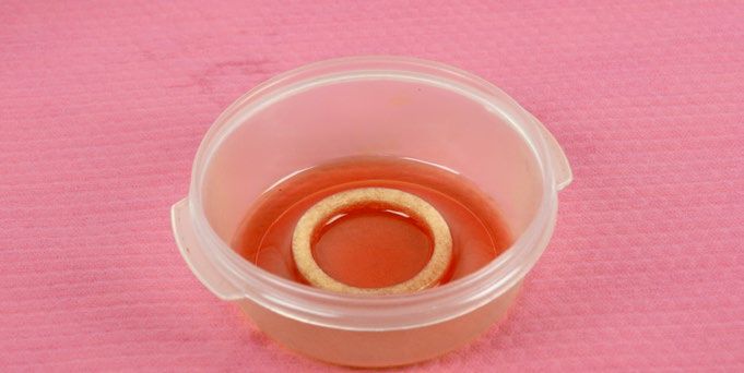
Exploded View - SID Ultimate \ Charger Race Day Damper

                                                                                                                            Air Spring Assembly

                                                                        Air valve cap
                                                                                                                            Compression Damper
                                                                                                                            Assembly

                                                                        Top cap                                             Rebound Damper
                                                                                                                            Assembly

                                                                        Bottomless Token(s)

                                                                        Upper tube
                            Lockout adjuster knob
                            and retaining screw
                            Top cap

                            Compression damper

                                         Lower leg

                                                     Brake hose guide

                                                                                                              Air piston

                                                                                                              Top out bumper cup

              Wiper seal
                                                                                                              Bumper cone

              Foam ring

                                                                                     Seal head

                                                                               Retaining ring
              Rebound damper shaft
                                                                                                 Jounce
                                                                                              bottom out
                                                                                                 bumper

                                                                                                 Air shaft

                                                                                             Bottom cup
 SID Ultimate R

                                                                                                             Crush washer
                           Spool and screw
                                                                                                              Bottom bolt

                                                            Crush washer
Cable
stop collar                                                  Rebound nut
and screw

                                                         Rebound adjuster

                                                                                        Exploded View - SID Ultimate \ Charger Race Day Damper    10
Exploded View - SID SL Select + \ Charger 2 Damper RL
Air Spring Assembly
Air valve cap
Compression Damper
Assembly
Top cap Rebound Damper
Assembly
Bottomless Token(s)
Lockout adjuster knob
and retaining screw
Upper tube
Top cap
Compression damper
Lower leg
Brake hose guide
Coupler
Cartridge Air piston
tube
Wiper seal Top out bumper cone
Foam ring
Dig Valve
Seal head
Seal head
Retaining ring
Rebound damper shaft
Jounce
bottom out
bumper
Air shaft
SID SL Select + RL R
Retention Bottom cup
Crush washer
screw
Spool Rebound nut
Crush washer
Rebound adjuster
Bottom bolt
Cable
stop collar
and screw
Exploded View - SID SL Select + \ Charger 2 Damper RL 11Exploded View - SID Select + \ Charger 2 Damper RL
Air Spring Assembly
Air valve cap
Compression Damper
Assembly
Top cap Rebound Damper
Assembly
Bottomless Token(s)
Lockout adjuster knob
and retaining screw
Upper tube
Compression top cap
Compression damper
Lower leg
Brake hose guide
Air piston
Coupler
Top out bumper cup
Cartridge
tube
Bumper cone
Wiper seal
Foam ring
Dig Valve Seal head
Seal head Retaining ring
Rebound damper shaft Jounce
bottom out
bumper
Air shaft
Bottom cup
SID Select + RL R
Crush washer
Retention Bottom bolt
Crush washer
screw
Spool Rebound nut
Rebound adjuster
Cable
stop collar
and screw
Exploded View - SID Select + \ Charger 2 Damper RL 12Exploded View - SID SL Select \ Charger Damper RL
Air Spring Assembly
Air valve cap
Compression Damper
Assembly
Top cap Rebound Damper
Assembly
Bottomless Token(s)
Lockout adjuster knob
and retaining screw
Upper tube
Compression top cap
Compression damper
Lower leg
Brake hose guide
Cartridge Air piston
tube
Wiper seal Top out bumper cone
Foam ring
Piston
Seal head
Seal head
Retaining ring
Rebound damper shaft
Jounce
bottom out
bumper
Air shaft
SID SL Select RL R
Retention Bottom cup
Crush washer
screw
Spool Rebound nut
Crush washer
Rebound adjuster
Bottom bolt
Cable
stop collar
and screw
Exploded View - SID SL Select \ Charger Damper RL 13Exploded View - SID Select \ Charger Damper RL
Air Spring Assembly
Air valve cap
Compression Damper
Assembly
Top cap Rebound Damper
Assembly
Bottomless Token(s)
Lockout adjuster knob
and retaining screw
Upper tube
Compression top cap
Compression damper
Lower leg
Brake hose guide
Air piston
Coupler
Top out bumper cup
Cartridge
tube
Bumper cone
Wiper seal
Foam ring
Piston Seal head
Seal head Retaining ring
Rebound damper shaft Jounce
bottom out
bumper
Air shaft
Bottom cup
SID Select RL R
Crush washer
Retention Bottom bolt
Crush washer
screw
Spool Rebound nut
Rebound adjuster
Cable
stop collar
and screw
Exploded View - SID Select \ Charger Damper RL 14Lower Leg Removal and Service
50/200 Hour Service Lower Leg Removal
1 Remove the air valve cap.
Ultimate Select/Select +
2 Depress the Schrader valve and release all air pressure.
⚠ CAUTION - EYE HAZARD
Verify all pressure is removed from the fork before proceeding.
Failure to do so can result in injury and/or damage to the fork. Wear
safety glasses.
Small Hex
3 Remove the rebound adjuster knob.
Ultimate Select/Select +
4 Place an oil pan beneath the fork to catch the draining oil.
Oil Pan
Lower Leg Removal and Service 155 Ultimate: Loosen the spring side bottom bolt 3 to 4 turns.
Select/Select+:: Loosen both bottom bolts 3 to 4 turns.
Select/Select+
Ultimate: 5 mm Spring Side Only Select / Select +: 5 mm Both Sides
6 Insert a 5 mm extension or hex wrench into the bolt head of the spring
side lower leg. Strike the wrench to dislodge the shaft from the lower
leg. The bolt head should contact the bottom of the lower leg.
Remove the spring side bottom bolt. Clean the bolt and set it aside.
Spring Side: 5 mm & Mallet Spring Side
7 Ultimate: Use a 10 mm socket and extension to remove the rebound
nut on the damper side lower leg.
Insert a 5 mm hex wrench into the rebound damper shaft. Strike the
wrench to dislodge the shaft from the lower leg.
Push the shaft into the lower leg.
Discard the crush washer and rebound nut.
Ultimate: 10 mm Damper Side Ultimate: 5 mm Damper Side
Ultimate: 5 mm Damper Side
Lower Leg Removal 168 Select/Select +: Insert a 5 mm extension or hex wrench into the bolt
head of the damper side lower leg. Strike the wrench to dislodge the
shaft from the lower leg. The bolt head should contact the bottom of
the lower leg. Remove the damper side bottom bolt. Clean the bolt
and set it aside.
Select / Select +: 5 mm & Mallet Damper Select / Select +: Damper Side
Side
9 Firmly pull the lower leg downward until fluid begins to drain. Continue
pulling downward to remove the lower leg.
If the lower leg does not slide off of the upper tube or if oil does not
drain from either side, the press fit of the shaft(s) into the lower leg
may still be engaged. Reinstall the bottom bolts 2 to 3 turns and repeat
the previous step.
NOTICE
Do not strike the fork arch with any tool when removing the lower leg
as this could damage the lower leg.
50 Hour Service Continue the 50 Hour Service with Lower Leg Service.
200 Hour Service Continue the 200 Hour Service with Lower Leg Seal Service.
Lower Leg Removal 1750 Hour Service Lower Leg Service
1 Remove the wire spring.
2 Remove the foam rings.
Pick
3 Clean the foam rings.
Lower Leg Service 184 Soak the foam rings in suspension oil.
0w-30
5 Remove the bottom out cup from the lower leg. Remove the jounce
bumper from the lower leg, if necessary. Clean the inside and outside
of the lower leg. Clean the wiper seals.
6 Install the foam rings under the wiper seals.
Confirm the foam rings are installed evenly in the space under the
wiper seals and do not protrude over the bushings.
Install the wire spring.
50 Hour Service Continue the 50 Hour Service with Lower Leg Installation.
Lower Leg Service 19200 Hour Service Lower Leg Seal Service
1 Remove the outer wire springs from the wiper seals.
Remove and discard the foam rings.
2 Stabilize the lower leg on a bench top or on the floor. Place the tip of
a downhill tire lever under the wiper seal. Press down on the downhill
tire lever handle to remove the seal.
Repeat on the other side. Discard the wiper seals.
NOTICE
Keep the lower leg stable. Do not allow the lower leg to twist in
opposite directions, compress toward each other, or be pulled apart.
This will damage the lower leg.
3 Remove the bottom cup from the lower leg. Remove the jounce
bumper from the lower leg, if necessary. Clean the inside and outside
of the lower leg.
Lower Leg Seal Service 204 Soak the new foam rings in RockShox suspension oil. Install the new
foam rings into the lower leg.
0w-30
5 Remove the outer wire spring from each new wiper seal and set them
aside.
6 SID SL: Use the 32 mm RockShox Dust Seal Installation tool.
SID: Use the 35 mm RockShox Dust Seal Installation tool.
Insert the narrow end of a new wiper seal into the recessed end of the
RockShox Dust Seal Installation tool.
SID SL: 32 mm
SID: 35 mm
Lower Leg Seal Service 217 Hold the lower leg steady and use a mallet to seat the dust wiper
seal into the lower leg until the seal surface is flush with the top of the
lower leg.
Repeat on the other side.
NOTICE
Only press the wiper seal into the lower leg until it is flush with the
top surface of the lower leg. Pressing the wiper seal below the top
surface of the lower leg will compress the foam rings.
8 Install the outer wire spring.
200 Hour Service Continue the 200 Hour Service with Air Spring Service .
Lower Leg Seal Service 22Air Spring Service
⚠ WARNING- EYE HAZARD
Verify all pressure is removed from the fork before proceeding. Depress the schrader valve again to remove any remaining air pressure. Failure to
do so can result in injury and/or damage to the fork.
Tr a v e l C h a n g e A d j u s t m e n t - O p t i o n a l
To increase or decrease the travel in your SID fork, the air spring must be replaced with the correct length air spring shaft assembly. Refer to the
RockShox Spare Parts Catalog available on our website at www.sram.com/service for spare part kit details.
B o t t o m l e s s To k e n - O p t i o n a l I n s t a l l a t i o n
Bottomless Tokens can be added to, or removed from, the air top cap to fine-tune the bottom out feel and spring curve. Bottomless Tokens reduce
the air volume in your fork to create greater ramp at the end of the fork travel. Add tokens to maintain your fork's bottomless feel.
1 Remove the top cap.
Top Cap/Cassette Tool
2 Thread a Bottomless Token into another token or into the bottom of
the top cap.
NOTICE
The maximum amount of Bottomless Tokens for all SID forks is
3 tokens. Do not exceed.
3 Tighten the token(s).
8 mm 4 N·m (35 in-lb) Top Cap/Cassette Tool
200 Hour Service Continue the 200 Hour Service for a DebonAir Spring.
Spring.
Air Spring Service 23200 Hour Service DebonAir Spring Service
⚠ WARNING- EYE HAZARD
Verify all pressure is removed from the fork before proceeding. Depress the Schrader valve again to remove any remaining air pressure. Failure to
do so can result in injury and/or damage to the fork.
1 Remove the top cap.
Top Cap/Cassette Tool
2 Remove the top cap o-ring. Install a new o-ring.
Do not apply grease to the top cap threads.
3 Remove the jounce bottom out bumper from the air shaft, if installed.
4 Push the air shaft into the upper tube to prevent it from getting
scratched while removing the retaining ring.
Place the tips of large retaining ring pliers into the eyelets of the
retaining ring.
NOTICE
Scratches on the air shaft will allow air to bypass the seal head into
the lower leg. Scratches can result in reduced spring performance.
Retaining Ring Pliers
DebonAir Spring Service 245 Firmly pull on the air shaft to remove the air spring assembly from the
upper tube. Clean and inspect the assembly for damage.
SID SL SID
6 Clean the inside and outside of the upper tube.
Inspect the inside and outside of the upper tube for damage.
NOTICE
Scratches on the inside surface of the upper tube can cause air to
leak. If an internal scratch is visible, then replace the crown steerer
upper tube (CSU).
DebonAir Spring Service 257 Remove the seal head from the air shaft.
SID: Remove the top out bumper cup, bumper cone, and seal head
from the air shaft.
Clean and inspect the shaft for damage.
NOTICE
Scratches on the air spring shaft can cause air to leak. If a scratch is
visible the air spring assembly may need to be replaced.
SID SL
SID SID
8 Remove the outer and inner o-rings on the seal head.
Clean the seal head.
Apply grease and install new o-rings.
SID SL SID SL
SID SID
DebonAir Spring Service 269 Remove the air piston outer o-ring.
Clean the air piston.
Apply grease and install a new o-ring.
SID SL SID
10 Apply a liberal amount of grease evenly around the end of a clean
plastic dowel, approximately 60 mm from one end. Use the dowel to
apply the grease to the inside surface of the upper tube, approximately
60 mm into the tube.
11 Apply a liberal amount of grease around the air shaft.
SID SL: Install the seal head assembly onto the air shaft.
SID: Install the top out bumper cup and bumper cone.
SID SL
SID SID
DebonAir Spring Service 2712 Apply a liberal amount of grease to the air piston.
SID SL SID
13 Insert the air spring assembly into the upper tube. Firmly push the air
piston into the upper tube.
Insert the seal head into the upper tube and firmly press it into the
upper tube until it stops.
SID SL SID
14 Retaining rings have a sharper-edged side and a rounder edged side.
Installing retaining rings with the sharper-edged side facing the tool
will allow for easier installation and removal.
Place the tips of the retaining ring pliers into the eyelets of the
retaining ring. Guide the retaining ring with your finger to prevent the
shaft from from getting scratched while installing the retaining ring.
Use the pliers to push the seal head into the upper tube while
installing the retaining ring into the groove. Release the retaining ring
pliers when the ring is fully seated in the groove.
Confirm the retaining ring is properly seated in the retaining ring
groove by using the retaining ring pliers to rotate the retaining ring
and seal head back and forth a few times, then firmly pull down on the Retaining Ring Pliers
air shaft.
NOTICE
Do not scratch the air spring shaft. Scratches on the air shaft will
allow air to bypass the seal head into the lower leg, resulting in
reduced spring performance.
DebonAir Spring Service 2815 Install the jounce bottom out bumper on the air shaft.
16 Inject or pour RockShox suspension oil into the air spring upper tube.
2 mL 0w-30
17 Install the top cap and tighten.
Top Cap/Cassette Tool 28 N·m (250 in-lb)
200 Hour Service Continue the 200 Hour Service for a Charger Race Day Damper.
200 Hour Service Continue the 200 Hour Service for a Charger 2 Damper.
200 Hour Service Continue the 200 Hour Service for a Charger Damper RL.
DebonAir Spring Service 29Charger Race Day Damper Service
200 Hour Service Charger Race Day Damper Removal
1 RL: Turn the lockout adjuster knob to the closed position. Loosen the
screw.
RL Locked 2 mm
RL: Turn the lockout adjuster knob to the open, unlocked position.
Remove the knob.
RL Unlocked RL
RL R: Loosen the remote spool screw and remove the remote spool.
RL R: 2 mm
RL R: Loosen the cable stop collar screw and remove the cable stop
collar.
RL R: 1.5 or 2 mm
Charger Race Day Damper Service 302 Remove the Race Day Damper assembly.
24 mm
Clean the upper tube threads.
3 Replace the o-ring on the top cap.
Charger Race Day Damper Removal 31200 Hour Service Bleed Procedure
1 Insert the rebound adjuster knob into the rebound shaft until it
contacts the rebound adjuster screw. Rotate the knob
counter-clockwise until it stops to open the rebound.
Remove the rebound adjuster knob from the shaft.
2.5 mm or Rebound Adjuster
2 Remove the bleed screw from the top cap.
⚠ CAUTION - EYE HAZARD
Oil will eject from the damper assembly if the shaft is compressed.
Wear safety glasses.
T10
3 Hold the damper over an oil pan. Compress the rebound shaft to
purge the oil from the port in the damper top cap. Cycle the rebound
shaft to empty the oil from the damper top cap.
⚠ CAUTION - EYE HAZARD
Oil will eject from the damper assembly. Hold the damper top cap
downward to avoid oil spray in the eyes.
4 Fill a bleed syringe full with suspension oil. Slowly depress the plunger
to remove any air bubbles from the syringe.
NOTICE
Only use the syringe included with the RockShox Standard Bleed kit.
Do not use syringes that have been in contact with DOT brake fluid.
DOT brake fluid will permanently damage the damper.
PLUSH 3wt RockShox Bleed Syringe
Bleed Procedure 325 Hold the damper vertically. Thread the syringe into the top cap bleed
port. Inject the oil into the damper assembly.
Release the plunger and air will purge into the syringe. Compress
and release the plunger to inject oil into the damper. Refill the syringe
when necessary.
6 Remove the bleed syringe from the top cap.
Make sure the rebound shaft is fully extended and there is a small
amount of positive pressure in the system before the syringe is
removed. This prevents air getting back into the damper.
Fill the bleed syringe half full with suspension oil. Slowly depress the
plunger to remove any air bubbles from the syringe.
NOTICE
Only use the syringe included with the RockShox Standard Bleed kit.
Do not use syringes that have been in contact with DOT brake fluid.
DOT brake fluid will permanently damage the damper.
7 Hold the damper vertically. Thread the syringe into the top cap bleed
port.
Bleed Procedure 338 Inject the oil into the damper assembly.
Push the assembly down to compress the rebound shaft. The syringe
will fill up.
Depress the syringe to inject oil into the damper assembly and allow
the rebound shaft to fully extend.
Repeat cycling the fluid 3-4 times.
9 Push the syringe handle down, then release the plunger. Allow
the bladder to come to a natural resting position by waiting a few
moments until the syringe stops filling.
Use a shop towel to cover the bleed tip and bleed port, then unthread
and remove the syringe.
Make sure the damper is fully extended and there is a small amount
of positive pressure in the system before the syringe is removed. This
prevents air getting back into the damper.
⚠ CAUTION - EYE HAZARD
Oil will eject from the bladder assembly if the bladder is not in its
resting position. Wear safety glasses.
10 Install the bleed screw.
T10
Bleed Procedure 3411 Rapidly push the rebound shaft in and out 15-20 times.
12 Compress the damper in a vertical position for five minutes. This will
allow the remaining bubbles to float to the top.
13 Extend the rebound shaft.
Remove the bleed screw. Thread a half full syringe into the bleed port.
⚠ CAUTION - EYE HAZARD
Oil will eject from the damper assembly if the rebound shaft is
compressed. Wear safety glasses.
T10
14 Push the assembly down to compress the rebound shaft. The syringe
will fill up.
Depress the syringe to inject oil into the damper assembly and allow
the rebound shaft to fully extend.
Repeat cycling the fluid 3-4 times.
If bubbles still purge, then repeat step 11-13 until there are no more
bubbles.
Bleed Procedure 3515 Push the syringe handle down, then release the plunger. Allow
the bladder to come to a natural resting position by waiting a few
moments until the syringe stops filling.
Use a shop towel to cover the bleed tip and bleed port, then unthread
and remove the syringe.
Make sure the damper is fully extended and there is a small amount
of positive pressure in the system before the syringe is removed. This
prevents air getting back into the damper.
⚠ CAUTION - EYE HAZARD
Oil will eject from the bladder assembly if the bladder is not in its
resting position. Wear safety glasses.
16 Install the bleed screw.
Cycle the rebound shaft a few times. If the damper still feels like it has
air inside, go back to step 10 and repeat.
Clean the Charger Race Day Damper assembly.
T10 1·7 N·m (15 in-lb)
Bleed Procedure 36200 Hour Service Charger Race Day Damper Installation
1 Install the Charger Race Day Damper into the damper side upper tube.
2 Install the top cap and tighten.
24 mm 28 N·m (250 in-lb)
3 RL: Set the lockout adjuster knob on the top cap pin so the screw is
facing toward the steerer tube in the unlocked position.
Rotate the lockout adjuster knob so the screw is facing forward in the
lockout position. Tighten the screw.
RL 2 mm 0.3 N·m (3 in-lb)
Charger Race Day Damper Installation 374 RL R: Install the cable stop collar with the housing guide oriented within
the 10 degree range in the diagram. ≈10°
NOTICE
The cable stop collar and remote cable housing must clear the lower
leg arch when the fork is fully compressed.
RL R
Tighten the set screw.
1.5 or 2 mm 0.3 N·m (3 in-lb)
Install the remote spool with the cable set screw oriented within the
20 degree range in the diagram.
≈20°
RL R RL R
Tighten the set screw.
2 mm 0.3 N·m (3 in-lb)
200 Hour Service Continue the 200 Hour Service with Lower Leg Installation.
Charger Race Day Damper Installation 38Charger 2 Damper Service
200 Hour Service Charger 2 Damper Removal
1 RL: Turn the lockout adjuster knob to the open, unlocked position.
Remove the knob.
RL Unlocked RL: 2 mm
2 RL R: Remove the cable stop collar. Remove the spool.
RL R: 2 mm RL R: 2 mm
3 Remove the Charger 2 Damper assembly.
Clean the upper tube threads.
RL: Top Cap/Cassette Tool RL R: 24 mm
Charger 2 Damper Service 394 Remove top cap o-ring. Install a new o-ring on the top cap.
5 Clamp the wrench flats of the Charger 2 Damper in a vise with the
rebound shaft oriented upward.
SID SID SL
6 Use the wrench flats and remove the rebound damper assembly. Wrap
a shop towel around the cartridge tube to absorb oil.
SID 19 mm SID SL 19 mm
7 Remove the cartridge tube from the vise and pour the oil into an
oil pan.
Squeeze the bladder to drain the oil from the top cap assembly into an
oil pan.
Charger 2 Damper Removal 408 Spray RockShox Suspension Cleaner or isopropyl alcohol into the
cartridge tube.
Squeeze the bladder 5-6 times to circulate the cleaner into the
damper.
Place the tube on a shop towel for a few minutes to allow any excess
cleaner to drain.
9 Dry the cartridge tube and compression damper assembly with
compressed air.
Air Compressor and Nozzle
10 Remove and discard the seal head on the rebound damper shaft.
11 Replace the glide ring on the rebound damper piston.
Charger 2 Damper Removal 4112 Apply grease to a new inner seal head o-ring. Install the seal head on
the rebound damper shaft.
Charger 2 Damper Removal 42200 Hour Service Bleed Procedure
1 Pour Maxima PLUSH suspension oil into the cartridge tube until it is
full.
Squeeze the bladder until trapped bubbles stop purging. Pour
additional oil into the cartridge tube until full.
RL3 / RLC3 - 7wt
RL / RL R - 3wt
3wt or 7wt
2 Remove the bleed screw from the rebound damper seal head.
T10
3 Insert the rebound adjuster knob into the rebound damper shaft until it
contacts the rebound adjuster screw. Rotate the knob
counter-clockwise until it stops to open the rebound.
Remove the rebound adjuster knob from the shaft.
2.5 mm or Rebound Adjuster Knob
4 Wrap a shop towel around the cartridge tube to absorb oil.
Install the rebound assembly into the cartridge tube.
Clamp the assembly into a vise. Tighten the rebound seal head.
19 mm 9 N·m (80 in-lb)
Bleed Procedure 435 Reposition the Charger 2 Damper in the vise at an angle with the
bleed port angled as upward as possible. Install the bottom bolt into
the rebound damper shaft 3-4 turns.
6 Fill a bleed syringe half full with suspension oil. Slowly depress the
plunger to remove any air bubbles from the syringe.
NOTICE
Only use the syringe included with the RockShox Standard Bleed kit.
Do not use syringes that have been in contact with DOT brake fluid.
DOT brake fluid will permanently damage the damper.
PLUSH 3wt or 7wt
7 Thread the syringe into the seal head bleed port.
Depress the plunger to pressurize the damper assembly.
8 Push the rebound damper shaft down. Keep pressure on the plunger
as the syringe fills with oil. Pull up slowly on the rebound damper shaft.
Keep pressure on the syringe as oil fills the system.
Repeat pushing and pulling the rebound damper shaft, keeping
pressure on the plunger, until only small bubbles emerge from the
damper.
Bleed Procedure 449 Fully extend the rebound damper shaft. Push the syringe handle
down, then release the plunger. Allow the bladder to come to a natural
resting position by waiting a few moments until the syringe stops
filling.
Use a shop towel to cover the bleed tip and charger bleed port, then
unthread and remove the syringe.
⚠ CAUTION - EYE HAZARD
Oil may eject from the bladder assembly if the bladder is not in its
resting position. Wear safety glasses.
10 Install the bleed screw.
Cycle the rebound damper shaft a few times.
T10 1.7 N·m (15 in-lb) T10 1.7 N·m (15 in-lb)
11 Remove the bottom bolt from rebound damper shaft.
Clean the Charger 2 Damper assembly.
Bleed Procedure 45Te s t t h e B l e e d
1 Use a 13 mm socket to manually lock out the damper. Push down on
the damper assembly to test the bleed. The shaft should not move
more than 2 mm if the bleed was successful.
If the shaft moves while locked out, repeat the bleed section.
≤2 mm
13 mm
200 Hour Service Continue the 200 Hour Service with Charger 2 Damper - Crown Installation.
200 Hour Service Continue the 200 Hour Service with Charger 2 Damper - Remote Installation.
Test the Bleed 46200 Hour Service Charger 2 Damper Installation - Crown
1 Install the Charger 2 Damper into the damper side upper tube.
2 Install the top cap and tighten.
Top Cap/Cassette Tool 28 N.m (250 in-lb)
3 RL: Install the lockout adjuster knob on the top cap so the knob rotates
from open to closed. Install and tighten the retention screw.
2 mm 1.4 N·m (12 in-lb)
200 Hour Service Continue the 200 Hour Service with Lower Leg Installation.
Charger 2 Damper Installation - Crown 47200 Hour Service Charger 2 Damper Installation - Remote
1 Install and tighten the Charger 2 Damper into the upper tube.
24 mm 28 N.m (250 in-lb)
2 RL R: Install the cable spool top.
87˚
RL R
Install and tighten the cable spool retention screw.
2 mm 1.4 N.m (12 in-lb)
Install the cable stop collar. Hand tighten the cable stop collar bolt,
and then tighten. Consult the remote user manual for cable installation
instructions.
NOTICE
Do not overtighten the cable stop collar bolt. Overtightening the bolt
may result in damage to the remote top cap and cause the cable
to rub.
2 mm 0.4 N.m (4 in-lb)
200 Hour Service Continue the 200 Hour Service with Lower Leg Installation.
Charger 2 Damper Installation - Remote 48Charger Damper RL Service
200 Hour Service Damper Removal
1 RL: Turn the compression adjuster knob counter-clockwise, to the full
open position, until it stops.
2 RL: Remove the retaining screw and remove the knob.
RL: 2.5 mm RL
3 RL R: Loosen the set screw and remove the cable spool and cable
stop collar.
RL R: 2.5 mm RL R
Charger Damper RL Service 494 Unthread the damper top cap and remove the damper assembly.
Clean the upper tube threads.
RL: Top Cap/Cassette Tool RL R: 24 mm
Damper Removal 50200 Hour Service Damper Service
1 Clamp the Charger Damper RL cartridge tube into a vise with Charger
vise blocks.
Vise with Charger Vise Blocks
Unthread the top cap from the cartridge.
NOTICE
The cartridge tube and vise block must be dry and free of oil to
provide enough grip to unthread the top cap. If the cartridge tube
slips, clean and dry the tube and vise blocks.
RL: Top Cap/Cassette Tool RL R: 24 mm
2 Carefully remove the compression damper.
3 Remove the cartridge tube and rebound damper assembly from the
vise and pour the oil into an oil pan.
Clean the exterior of the cartridge tube.
Damper Service 514 Clamp the cartridge tube into a vise with Charger vise blocks. Use the
seal head wrench flats and remove the rebound damper assembly.
Vise with Charger Vise Blocks 19 mm
5 Remove the seal head from the rebound damper shaft.
Discard the seal head.
6 Spray RockShox Suspension Cleaner or isopropyl alcohol into the
cartridge tube and clean the inside of the tube with a shop towel and a
thin dowel (≤16 mm diameter).
Inspect the inside of the cartridge tube for scratches.
NOTICE
Scratches on the inside surface of the tube can cause oil to leak. If an
internal scratch is visible, the cartridge tube may need to be replaced.
Damper Service 527 Remove the o-rings from the compression damper and discard them.
Apply grease to new o-rings and install them.
8 Remove the glide ring from the rebound damper piston and discard it.
Install a new glide ring.
9 Apply grease to the inner seal and bushing in the new rebound
damper seal head.
Damper Service 53200 Hour Service Damper Assembly
1 Apply grease to the rebound damper shaft. Insert the rebound damper
shaft into the recessed end of the seal head.
Slide the seal head toward the piston.
2 Insert the rebound adjuster knob into the rebound damper and rotate
it counter-clockwise until it stops. This is the full open position.
2.5 mm hex or Rebound Adjuster Knob
Damper Assembly 543 Thread the cartridge tube into the seal head hand tight.
Pull the damper shaft to full extension.
4 Clamp the Charger Damper RL cartridge tube into a vise with Charger
vise blocks.
Thread a bottom bolt into the rebound damper shaft.
Vise with Charger Vise Blocks
5 Pour Maxima PLUSH 3wt suspension oil into the tube until it is almost
half full. Slowly cycle the rebound damper shaft in and out half way to
remove air bubbles trapped under the rebound damper piston. Stop
when no bubbles are visible in the oil.
PLUSH 3wt
Damper Assembly 556 Push the rebound damper into the cartridge tube until the rebound
shaft is extended to the A measurement. Do not push the damper into
the tube any further.
Fork travel (mm) A (mm)
100 112
A
120 92
See Table for Value
7 Pour Maxima PLUSH 3wt suspension oil into the tube until the oil is
just below the purge holes.
PLUSH 3wt
8 Insert the compression damper into the cartridge tube and slowly
push it into the tube. The rebound damper will slowly extend as the
compression damper is installed; this is normal.
Firmly push down and thread the top cap into the tube.
Damper Assembly 569 Tighten the top cap.
Tighten the rebound damper seal head.
Top Cap/Cassette Tool 9 N.m (80 in-lb) 24 mm 9 N.m (80 in-lb)
19 mm 9 N.m (80 in-lb)
10 Pull the rebound damper to full extension.
Use the table to find the B measurement for your fork's travel. Secure
a plastic cable tie around the shaft at the B dimension for your fork's
travel.
Do not push the damper into the tube any further. B
Fork travel (mm) B (mm)
100 55
120 34
See Table for Value
11 Remove the damper from the vise. Loosely wrap a shop towel over the
damper cartridge purge holes. Hold the damper vertical and slowly
pull the shaft out to full extension. Slowly push the rebound damper
shaft into the tube until the cable tie contacts the seal head, then stop.
Do not push the damper in any further.
Repeat 3-5 more times. This will allow any excess oil and air to escape
from the system.
Remove the bottom bolt. Clean the damper. Do not remove the cable
tie.
⚠ CAUTION
Oil may exit the cartridge tube purge holes. Wear safety glasses
and keep your eyes and face away from the purge holes when
compressing the rebound damper.
Damper Assembly 57Te s t C o m p r e s s i o n
1 RL: Use the adjuster knob to rotate the compression cam clockwise,
until it stops, to the firm position.
RL R: Use a 7 mm wrench to hold the cam closed, full clockwise until it
stops, while compressing the damper.
The cable tie must remain at 55 mm (100 mm travel forks) or 34 mm
(120 mm travel forks), from the end of the shaft. Do not compress the
rebound damper further than this point.
Cover the purge holes with a shop towel.
⚠ CAUTION
Oil may exit the cartridge tube purge holes. Wear saftey glasses
and keep your eyes and face away from the purge holes when RL RL R: 7 mm
compressing the rebound damper.
Push down on the damper assembly slowly to test the firmest
compression setting. Firm and consistent resistance should be felt with
no gaps in movement.
Rotate the compression damper to open setting and repeat the
compression test. Light consistent resistance should be felt with no
gaps in movement.
If gaps are felt during compression, repeat the oil fill and purge
process. If the assembly process was successful, set the compression
damper to the open setting and remove the cable tie.
RL RL R: 7 mm
Test Compression 58200 Hour Service Damper Installation
1 Install the Charger Damper RL or RL R assembly into the damper side
upper tube. Thread the top cap into the upper tube and tighten it.
RL: Top Cap/Cassette Tool 28 N.m (250 in-lb) RL R: 24 mm
2 RL: Install the adjuster knob with the tab in the 7-8 o'clock, unlocked
RL:
position.
Install and tighten the retaining screw.
RL
2.5 mm 1.4 N.m (12 in-lb)
Damper Installation 593 RL R:
R: Install the cable stop collar with the housing guide oriented
outward within the 75 degree range in the diagram.
NOTICE
The cable stop collar and remote cable housing must clear the lower
leg arch when the fork is fully compressed.
≈75°
RL R
Tighten the set screw.
2 mm 0.5 N·m (4 in-lb)
Install the remote spool onto the hex adjuster with the cable set screw
oriented within the 20 degree range in the diagram.
≈20°
RL R RL R
Install and tighten the remote spool retaining screw.
Consult the applicable user manual at
www.sram.com/service
www.sram.com/service for cable and remote installation instructions.
RL R: 2.5 mm 1.4 N·m (12 in-lb)
200 Hour Service Continue the 200 Hour Service with Lower Leg Installation.
Installation.
Damper Installation 60You can also read