2015-2018 BOXXER TEAM - SERVICE MANUAL - SRAM
←
→
Page content transcription
If your browser does not render page correctly, please read the page content below
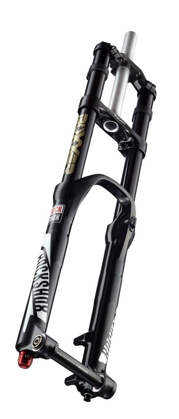
2015-2018
BoXXer® Team
           Service Manual

                GEN.0000000005721 Rev A
                        © 2018 SRAM, LLC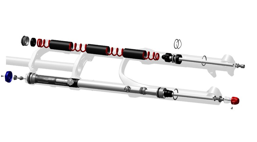
SRAM® LLC WARRANTY
EXTENT OF LIMITED WARRANTY
Except as otherwise set forth herein, SRAM warrants its products to be free from defects in materials or workmanship for a period of two years after
original purchase. This warranty only applies to the original owner and is not transferable. Claims under this warranty must be made through the retailer
where the bicycle or the SRAM component was purchased. Original proof of purchase is required. Except as described herein, SRAM makes no
other warranties, guaranties, or representations of any type (express or implied), and all warranties (including any implied warranties of
reasonable care, merchantibility, or fitness for a particular purpose) are hereby disclaimed.

LOCAL LAW
This warranty statement gives the customer specific legal rights. The customer may also have other rights which vary from state to state (USA), from
province to province (Canada), and from country to country elsewhere in the world.
To the extent that this warranty statement is inconsistent with the local law, this warranty shall be deemed modified to be consistent with such law, under
such local law, certain disclaimers and limitations of this warranty statement may apply to the customer. For example, some states in the United States
of America, as well as some governments outside of the United States (including provinces in Canada) may:
  a. Preclude the disclaimers and limitations of this warranty statement from limiting the statutory rights of the consumer
     (e.g. United Kingdom).
  b. Otherwise restrict the ability of a manufacturer to enforce such disclaimers or limitations.
For Australian customers:
This SRAM limited warranty is provided in Australia by SRAM LLC, 1000 W. Fulton Market, 4th Floor, Chicago, IL, 60607, USA. To make a warranty
claim please contact the retailer from whom you purchased this SRAM product. Alternatively, you may make a claim by contacting SRAM Australia, 6
Marco Court, Rowville 3178, Australia. For valid claims SRAM will, at its option, either repair or replace your SRAM product. Any expenses incurred in
making the warranty claim are your responsibility. The benefits given by this warranty are additional to other rights and remedies that you may have
under laws relating to our products. Our goods come with guarantees that cannot be excluded under the Australian Consumer Law. You are entitled to
a replacement or refund for a major failure and for compensation for any other reasonably foreseeable loss or damage. You are also entitled to have the
goods repaired or replaced if the goods fail to be of acceptable quality and the failure does not amount to a major failure.

LIMITATIONS OF LIABILITY
To the extent allowed by local law, except for the obligations specifically set forth in this warranty statement, in no event shall SRAM or its third party
suppliers be liable for direct, indirect, special, incidental, or consequential damages.

LIMITATIONS OF WARRANTY
This warranty does not apply to products that have been incorrectly installed and/or adjusted according to the respective SRAM user manual. The SRAM
user manuals can be found online at sram.com, rockshox.com, avidbike.com, truvativ.com, or zipp.com.
This warranty does not apply to damage to the product caused by a crash, impact, abuse of the product, non-compliance with manufacturers
specifications of usage or any other circumstances in which the product has been subjected to forces or loads beyond its design.
This warranty does not apply when the product has been modified, including, but not limited to any attempt to open or repair any electronic and
electronic related components, including the motor, controller, battery packs, wiring harnesses, switches, and chargers.
This warranty does not apply when the serial number or production code has been deliberately altered, defaced or removed.
This warranty does not apply to normal wear and tear. Wear and tear parts are subject to damage as a result of normal use, failure to service according
to SRAM recommendations and/or riding or installation in conditions or applications other than recommended.
Wear and tear parts are identified as:

• Dust seals                            • Stripped threads/bolts (aluminium,    • Handlebar grips                       • Transmission gears
• Bushings                                titanium, magnesium or steel)         • Shifter grips                         • Spokes
• Air sealing o-rings                   • Brake sleeves                         • Jockey wheels                         • Free hubs
• Glide rings                           • Brake pads                            • Disc brake rotors                     • Aero bar pads
• Rubber moving parts                   • Chains                                • Wheel braking surfaces                • Corrosion
• Foam rings                            • Sprockets                             • Bottomout pads                        • Tools
• Rear shock mounting hardware          • Cassettes                             • Bearings                              • Motors
  and main seals                        • Shifter and brake cables (inner       • Bearing races                         • Batteries
• Upper tubes (stanchions)                and outer)                            • Pawls

Notwithstanding anything else set forth herein, the battery pack and charger warranty does not include damage from power surges, use of improper
charger, improper maintenance, or such other misuse.
This warranty shall not cover damages caused by the use of parts of different manufacturers.
This warranty shall not cover damages caused by the use of parts that are not compatible, suitable and/or authorised by SRAM for use with SRAM
components.
This warranty shall not cover damages resulting from commercial (rental) use.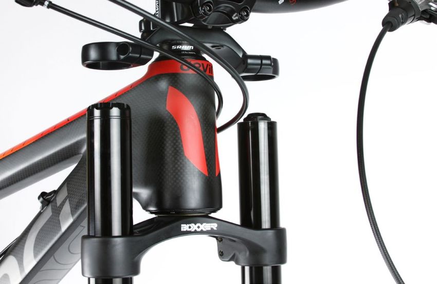
TABLE OF CONTENTS
BOXXER® TEAM EXPLODED VIEW.................................................................................................................................................. 5

ROCKSHOX® SUSPENSION SERVICE.............................................................................................................................................. 6
      PARTS AND TOOLS NEEDED FOR SERVICE............................................................................................................................................................................ 6
      RECORD YOUR SETTINGS.................................................................................................................................................................................................................7
      SERVICE INTERVAL INFORMATION..............................................................................................................................................................................................7
      BOXXER TORQUE CHART..................................................................................................................................................................................................................7
      BOXXER OIL VOLUME.........................................................................................................................................................................................................................7

FORK REMOVAL.................................................................................................................................................................................. 8

LOWER LEG REMOVAL.................................................................................................................................................................... 10
      LOWER LEG SEAL SERVICE............................................................................................................................................................................................................ 13

COIL SPRING SERVICE.................................................................................................................................................................... 16
      COIL SPRING REMOVAL...................................................................................................................................................................................................................16
      COIL SPRING INSTALLATION.........................................................................................................................................................................................................19

CHARGER DAMPER™ SERVICE.......................................................................................................................................................21
      CHARGER DAMPER REMOVAL...................................................................................................................................................................................................... 21

OPTIONAL CHARGER DAMPER RE-TUNE....................................................................................................................................30
      OPTIONAL REBOUND RE-TUNE..................................................................................................................................................................................................30
      OPTIONAL COMPRESSION RE-TUNE........................................................................................................................................................................................ 33

CHARGER DAMPER ASSEMBLY AND BLEED.............................................................................................................................. 37

LOWER LEG ASSEMBLY..................................................................................................................................................................47

FORK INSTALLATION......................................................................................................................................................................49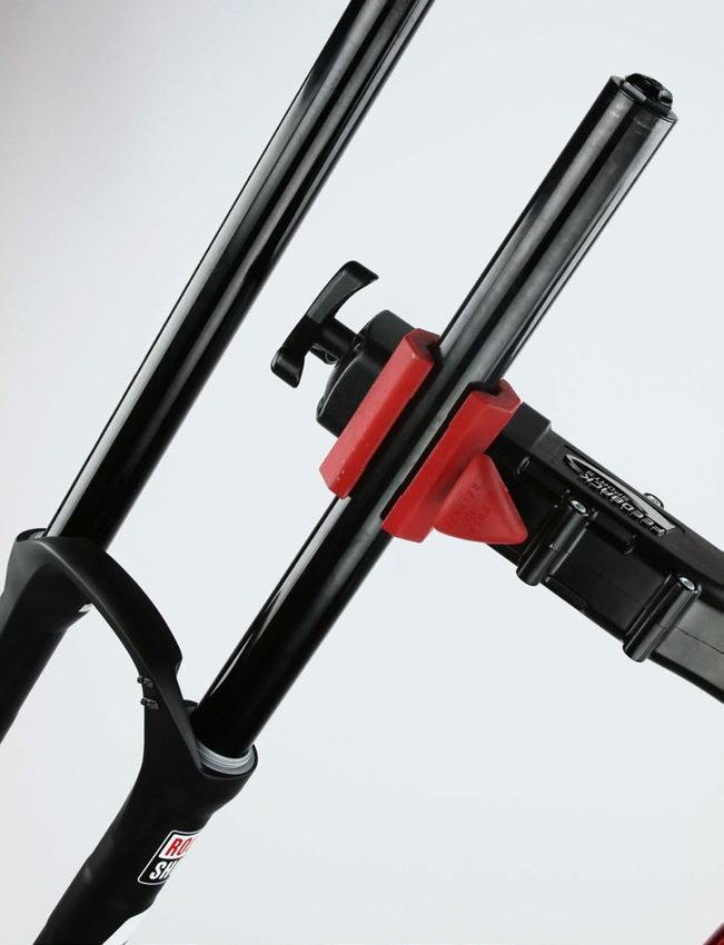
SAFETY FIRST!
We care about YOU. Please, always wear your safety glasses and
    protective gloves when servicing RockShox® products.
           Protect yourself! Wear your safety gear!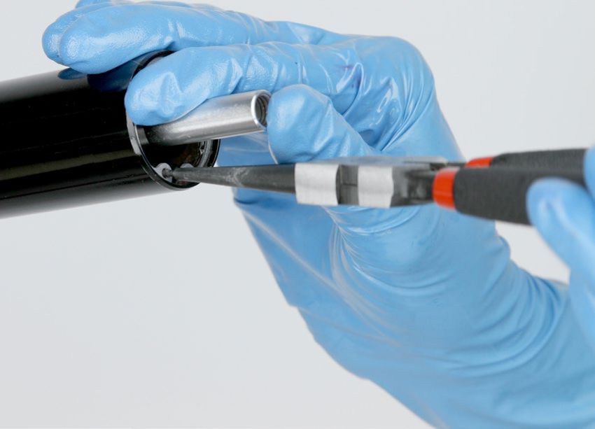
B o X Xe r ® Te a m E x p l o d e d V i e w
                                                                                          Top cap

Knob retaining screw                                                                      Preload spacers (5 maximum)

Low speed compression
adjuster knob                                                                             Upper crown

Retaining nut

                                                                                          Spring isolator
Low speed compression adjuster

Compression top cap

                                                                                                                 Coil spring

Bladder and bladder sleeve                                                                                       Steerer tube

                                                                                                                 Lower crown

Low speed compression needle

Compression piston assembly

Coupler

                                 Cartridge tube

                                 Upper tube

                                 Rebound damper piston assembly

                                                                                                                                   Spring perch
                                 Lower leg
                                                                                                                                   Support washer

                                                                                                                                   Wavy washer

                                 Rebound damper seal head                                                                          Base plate assembly

                                                                                                                                   Spring shaft assembly

                                       Lower seal head
                                                                                                                                   Retaining ring

                                       Bottom out bumper

                                       Retaining ring

                                                                  Rebound damper shaft                                                      Crush washer
                                                                                                                                            Crush washer retainer
                                                                                                                                            Bottom bolt
                                                                  Crush washer

                                                                  Bottom bolt

                                                                  Set screw

                                                                  Rebound adjuster knob

                                                                                                                    BoXXer® Team Exploded View             5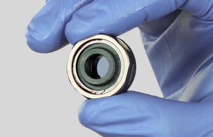
RockShox® Suspension Service
We recommend that you have your RockShox suspension serviced by a qualified bicycle mechanic. Servicing RockShox suspension
requires knowledge of suspension components as well as the special tools and fluids used for service.
For exploded diagram and part number information, please refer to the Spare Parts Catalog available on our website at
www.sram.com/service. For order information, please contact your local SRAM® distributor or dealer.
Information contained in this publication is subject to change at any time without prior notice. For the latest technical information,
please visit our website at www.sram.com/service.
Your product's appearance may differ from the pictures contained in this publication.

P a r t s a n d To o l s N e e d e d f o r S e r v i c e
•   Safety glasses                                                    •   Schrader valve core tool
•   Nitrile gloves                                                    •   21, 23, and 25 mm open end wrenches
•   Apron                                                             •   21, 23, and 25 mm crowfoot wrenches
•   Clean, lint-free rags                                             •   2, 2.5, 4, 5, 6, and 8 mm hex wrenches
•   Oil pan                                                           •   5/8", 2, 2.5, 4, 5, and 6 mm hex bit sockets
•   Isopropyl alcohol                                                 •   6, 10, 15, and 24 mm socket wrenches
•   Bicycle stand                                                     •   Torque wrench
•   Bench vise with aluminum soft jaws                                •   Needle-nose pliers
•   RockShox 3wt suspension fluid                                     •   Large internal snap ring pliers
•   RockShox 0w-30 suspension fluid                                   •   Pick
•   SRAM Butter grease                                                •   Long plastic or wooden dowel
•   Liquid O-Ring® PM600 military grease                              •   RockShox syringe with Charger™ bleed tip
•   Shock pump                                                        •   Loctite® Threadlocker Blue 242™
•   35 mm seal installation tool                                      •   Loctite Threadlocker Red 2760™
•   Downhill tire lever                                               •   Metric calipers (for re-tuning shim stacks)
•   Plastic mallet                                                    •   Ruler
•   Flat head screwdriver                                             •   RockShox Rear Shock Vise Block (for re-tuning shim stacks)
•   Diagonal cutter (26")                                             •   Cable tie (26")
                                                                      •   Heat gun or hair dryer

                                                  SAFETY INSTRUCTIONS
Always wear nitrile gloves when working with suspension fluid and bicycle grease.
Place an oil pan on the floor underneath the area where you will be working on the fork.

                                                                                                      RockShox® Suspension Service       6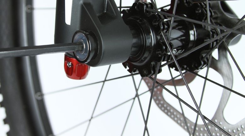
Record your Settings
Use the charts below to record your BoXXer® fork settings to return your fork to its pre-service settings. Record your service date to
track service intervals.

  Service date - helps you keep track of service intervals.

  Dual Crown height - measure the distance from the top of the upper to tube to the top of the
  lower crown (see figure in Step 1).
  Rebound setting - count the number of clicks while turning the rebound adjuster fully
  counter-clockwise.
  Compression setting - count the number of clicks while turning the compression adjuster fully
  counter-clockwise.

Service Interval Information

  Maintenance                                                                                         Interval (hours)
  Clean dirt and debris from upper tubes                                                              Every ride
  Inspect upper tubes for scratches                                                                   Every ride
  Check front suspension fasteners for proper torque                                                  25
  Remove lowers, clean/inspect bushings and change oil bath                                           50
  Clean and lubricate coil spring assembly                                                            100
  Change oil in damping system                                                                        100

B o X X e r To r q u e C h a r t

  Part                                                             Tool                               Torque
  Maxle Lite DH™ (non-drive side)                                   6 mm hex bit socket               3.4 N•m (30 in-lb)
  Maxle Lite DH (drive side)                                        6 mm hex bit socket               5.7 N•m (50 in-lb)
  Crown bolts                                                       4 mm hex bit socket               5 N•m (44 in-lb)
  Bottom bolts                                                      5 mm hex bit socket               7.3 N•m (65 in-lb)
  Top caps                                                          24 mm socket                      7.3 N•m (65 in-lb)

BoXXer Oil Volume

  Part                                                             Oil Weight                         Volume (mL)
  Drive side lower leg                                                                                10
                                                                    0w-30
  Non-drive side lower leg                                                                            20
  Drive side upper tube                                             3wt                               Bleed (varies)
  Non-drive side upper tube                                         Liquid O-Ring® PM600 military grease

                                                                                                               Record your Settings      7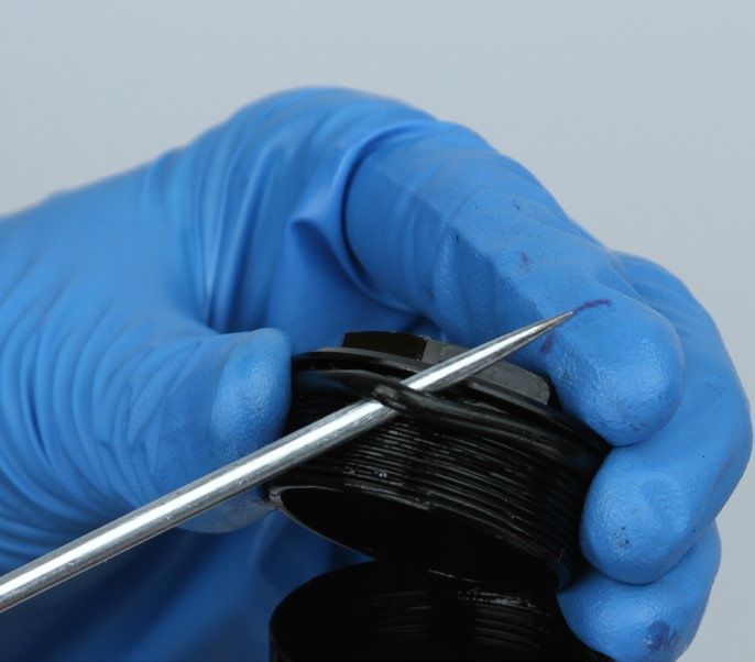
Fork Removal
We recommend the following steps to remove your BoXXer® fork from the bicycle. Removing the fork from the bicycle provides easy
access to internal components and is more convenient than working around a complete bicycle.

     To assist you with post-service assembly, record the distance from
 1   the top of the upper tube to the top of the lower crown.

     Use a 6 mm hex wrench to loosen the non-drive side bolt of the
 2   Maxle Lite DH™ until detent clicks are no longer felt.

                                                                            6 mm

     Use a 6 mm hex wrench to remove the Maxle Lite DH from the
 3   drive side of the fork. Pull the wheel down to remove it from the
     fork.

                                                                            6 mm

     27.5" forks: Use a 2.5 mm hex wrench to remove the brake hose
 4   from the hose brace on the fork arch.
     26" forks: Use a diagonal cutter to cut the cable tie holding the
     brake hose to the fork arch.
     Remove the brake caliper according to the brake manufacturer's
     instructions.

                                                                                                               Fork Removal       8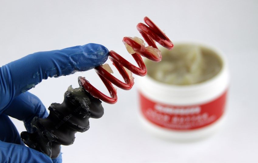
Use a 4 mm hex wrench to loosen the four lower crown and two
5   upper crown pinch bolts clamping the upper tubes.
                                                                                               4 mm    Upper crown

    Do not loosen the steerer tube clamping bolt located on the
    upper crown.

                                                                        4 mm     Lower crown

    Slide the upper tubes down so they clear the upper crown. Leave
6   enough clearance between the upper tube and upper crown to
    remove the frame bumpers.
    Use a 4 mm hex wrench to tighten one of the lower crown bolts
    to temporarily hold the tubes in place while you remove the frame
    bumpers.

                                                                          4 mm

    Use your thumb to pry the thickest section of each frame bumper
7   away from the upper tube. Spray isopropyl alcohol or water
    between each bumper and upper tube. Twist the frame bumpers
    back and forth until they are loose on the upper tubes.
    Remove the frame bumpers from the upper tubes.

    Use a 4 mm hex wrench to loosen the lower crown bolt. Slide
8   the tubes through the lower crown and remove the fork from the
    bicycle.
    Spray isopropyl alcohol on the upper tubes and crown clamping
    surface and clean them with a rag.

                                                                          4 mm

                                                                                                      Fork Removal   9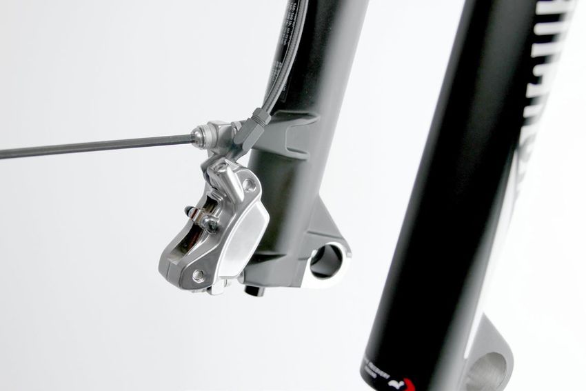
Lower Leg Removal
    Clamp the non-drive side upper tube into a bicycle stand.
1

                                                                                             Non-drive side

    Use a 5 mm hex wrench to loosen the non-drive side bottom bolt
2   3 to 4 turns.

                                                                          5 mm             Loosen 3 to 4 turns

    Place an oil pan beneath the fork to catch any draining fluid. Use
3   a plastic mallet to firmly strike the non-drive side bottom bolt to
                                                                                                      5 mm

    dislodge the spring shaft from the lower leg.
    Use a 5 mm hex wrench to remove the bottom bolt from the lower
    leg.

                                                                          Plastic mallet

    Firmly pull the lower leg downward until fluid begins to drain.
4   Continue pulling downward to remove the lower leg from the
    non-drive side upper tube.
    If the lower leg does not slide off of the upper tube, then the
    press-fit of the shaft to the lower leg may still be engaged.
    Reinstall the bottom bolt 2 to 3 turns and repeat steps 2-4.

                               NOTIC E
    Do not hit the fork arch with any tool when removing the lower leg
    as this could damage the lower leg.

                                                                                                          Lower Leg Removal   10
Clamp the drive side upper tube into a bicycle stand.
5
Drive side
Use a 2.5 mm hex wrench to loosen the set screw and remove the
6 rebound adjuster knob located at the bottom of the drive side
lower leg.
2.5 mm
Use a 5 mm hex wrench to loosen the drive side bottom bolt 3 to
7 4 turns.
5 mm Loosen 3 to 4 turns
Place an oil pan beneath the fork to catch any draining fluid.
8 Use a plastic mallet to firmly strike the drive side bottom bolt to
5 mm
dislodge the rebound damper shaft from the lower leg.
Use a 5 mm hex wrench to remove the bottom bolt from the lower
leg.
Do not dislodge the silver casting plug from the drive side lower
leg.
Plastic mallet
Lower Leg Removal 11Firmly pull the lower leg downward until fluid begins to drain.
9 Continue pulling downward to remove the lower leg from the fork.
If the lower leg does not slide off of the upper tube, then the
press-fit of the shaft to the lower leg may still be engaged.
Reinstall the bottom bolt 2 to 3 turns and repeat steps 7-9.
NOTIC E
Do not hit the fork arch with any tool when removing the lower leg
as this could damage the fork.
Lower Leg Removal 12Lower Leg Seal Service
Place the tip of a downhill tire lever underneath the lower lip of the
1 dust wiper seal.
NOTIC E
If using a flat blade screwdriver, make sure it has a round shaft. A
screwdriver with a square shaft will damage the fork leg.
Stabilize the lower leg on a bench top or on the floor. Press down
2 on the tire lever handle to remove the dust wiper seal.
Repeat on the other side.
NOTIC E
Keep the lower leg assembly stable. Do not allow the lower leg to
twist in opposite directions, compress toward each other, or be
pulled apart. This will damage the lower leg.
Use your fingers to remove and discard the foam rings inside the
3 lower leg.
Soak the new foam rings in RockShox® 0w-30 suspension fluid.
4
Lower Leg Seal Service 13Spray isopropyl alcohol on the inside and outside of the lower leg.
5 Clean the outside of the lower leg with a rag.
Wrap a rag around a long dowel and insert it into each lower leg to
clean the inside of the lower leg.
Reinstall new foam rings on the top bushings in the lower leg.
6
Remove the wire spring from the new dust wiper seal and set it
7 aside.
Insert the narrow end of a new dust wiper seal into the recessed
8 end of the seal installation tool.
Lower Leg Seal Service 14Hold the lower leg steady and use the seal installation tool to press
9 the dust wiper seal evenly into the lower leg until the seal surface
is flush with the top of the lower leg surface.
Reinstall the wire spring onto the dust wiper seal.
Repeat steps 7, 8, and 9 for the other side of the lower leg.
NOTIC E
Only press the dust wiper seal into the lower leg until it is flush
with the top surface of the lower leg. Pressing the dust wiper seal
past the top surface of the lower leg can damage the foam rings.
Lower Leg Seal Service 15Coil Spring Service
Coil Spring Removal
NOTIC E
Inspect each part for scratches. Do not scratch any sealing surfaces when servicing your suspension. Scratches can cause leaks.
When replacing seals and o-rings, use your fingers or a pick to remove the seal or o-ring. Spray isopropyl alcohol on each part and clean
with a rag. Apply SRAM® Butter grease to the new seal or o-ring.
Clamp the non-drive side upper tube into a bicycle stand.
1
Non-drive side
Use a 24 mm socket to remove the top cap.
2
Spray isopropyl alcohol on the upper tube threads and clean the
threads with a rag.
24 mm
Use your fingers or a pick to remove the top cap o-ring. Use your
3 fingers to install a new o-ring.
Coil Spring Service 16Use your fingers to remove the preload spacer(s). Pull the coil
4 spring from the upper tube.
Spray isopropyl alcohol on the preload spacer(s), coil spring, and
upper tube threads and clean them with a rag.
Verify the three isolators are evenly spaced along the coil spring
5 with approximately 50 mm of exposed coil at each end.
To reposition an isolator, thread it along the coil by hand. Use
a heat gun or hair dryer to shrink and secure the isolator in its
position. Gradually heat the isolator until it emits a vapor.
CAUTION - BU RN HAZARD
Do not get the heat gun or hair dryer too close to the isolator.
Failure to do so may result in a burn hole in the isolator. Allow the
isolator to cool down before handling. Failure to do so may result
in burns.
Place the tips of large internal snap ring pliers into the eyelets of
6 the retaining ring. Press firmly on the pliers to push the base plate
into the upper tube enough to compress and remove the retaining
ring.
Slide the retaining ring onto your finger and release the spring
shaft.
Snap ring pliers
Remove the spring shaft assembly from the upper tube.
7
Coil Spring Removal 17Spray isopropyl alcohol on the inside and outside of the upper
8 tube and clean it with a rag.
Wrap a rag around a long dowel and insert it into the upper tube
to clean inside the upper tube.
Remove the base plate assembly, wavy washer and support
9 washer from the spring shaft.
Spray isopropyl alcohol on the spring shaft, spring perch and base
plate assembly and clean them with a rag.
Coil Spring Removal 18Coil Spring Installation
Install a new support washer and a new wavy washer on the spring
1 shaft so that the support washer is closest to the spring perch.
Install the base plate assembly onto the spring shaft so that the
small top out spring is oriented toward the spring perch.
Firmly push the spring shaft assembly into the bottom of the
2 upper tube until the retaining ring groove is visible.
Place the tips of large internal snap ring pliers into the eyelets of
3 the retaining ring and install the retaining ring into the groove.
Check that the retaining ring is properly seated in the retaining
ring groove by using the snap ring pliers to rotate the retaining
ring and seal head back and forth a few times, then firmly pull
down on the spring shaft.
Retaining rings have a sharper-edged side and a rounder-edged
side. Installing retaining rings with the sharper-edged side facing
the tool will allow for easier installation and removal.
Coil Spring Installation 19Apply a generous amount of SRAM® Butter grease to the coil
4 spring.
Use a measuring device to Identify the end of the coil spring with
a smaller diameter.
Install the smaller end of the coil spring into the top of the upper
tube.
SRAM Butter grease only
Small end first
Use a measuring device to measure the distance from the top of
5 the coil spring to the top of the upper tube. The distance should
5 max
be less than 16 mm.
Add up to five preload spacers to achieve a distance of 16 mm or
your desired preload setting.
NOTIC E
Installing more than five preload spacers into the upper tube will
cause damage to your fork.
< 16 mm
Insert the top cap into the top of the upper tube.
6
Use a torque wrench with a 24 mm socket to tighten the top cap
to 7.3 N·m (65 in-lb).
24 mm 7.3 N•m (65 in-lb)
Coil Spring Installation 20Charger Damper™ Service
Charger Damper Removal
NOTIC E
Use aluminum soft jaws to protect the Charger Damper assembly when using a vice.
Inspect each part for scratches. Do not scratch any sealing surfaces when servicing your suspension. Scratches can cause leaks.
When replacing seals and o-rings, use your fingers or a pick to remove the seal or o-ring. Spray isopropyl alcohol on each part and clean
with a rag. Apply SRAM® Butter to the new seal or o-ring.
Clamp the drive side upper tube into a bicycle stand.
1
Drive side
Use your fingers to remove the bottom out bumper from the
2 rebound damper shaft.
Use a 2 mm hex wrench to remove the knob retaining screw.
3 Remove the low speed compression adjuster knob.
2 mm
Charger Damper™ Service 21Use a 24 mm socket to loosen the compression top cap. Remove
4 the Charger Damper™ assembly from the upper tube.
Clean the upper tube threads with a rag.
24 mm
Use a pick or your fingers to remove the compression top cap
5 o-ring. Install a new compression top cap o-ring.
Use large internal snap ring pliers to remove the retaining ring
6 from the bottom of the upper tube.
Snap ring pliers
Insert a long dowel into the top of the upper tube and push the
7 lower seal head out the bottom of the upper tube.
Charger Damper Removal 22Use your fingers to remove the outer o-ring on the lower seal
8 head. Use a pick to pierce and remove the inner scraper seal from
the lower seal head.
Use your fingers to install a new o-ring and scraper seal on the
lower seal head.
Scraper seal orientation
Remove the drive side upper tube from the bicycle stand.
9
Clamp the cartridge tube into a bicycle stand with the rebound
damper oriented upward.
Charger Damper Removal 23Identify the manufacturing date code on your fork by looking on
10 the back side of the crown. The code is broken up into sections:
the first two numbers are the week the fork was made, the letter is
the factory code, the following number is the last digit of the year,
and the rest of the code is the serial number for the fork. Only the
first four digits are important to this step.
Manufacturing date code before 26T5: Place a 21 mm open end
wrench on the wrench flats of the cartridge tube. Place another
21 mm open end wrench on the damper seal head.
Holding the cartridge tube in place, turn the damper seal head
counter-clockwise to loosen and remove the rebound assembly.
21 mm
Manufacturing date code after 26T5: Place a 21 mm open end
wrench on the wrench flats of the cartridge tube. Place a 23 mm
open end wrench on the damper seal head.
Holding the cartridge tube in place, turn the damper seal head
counter-clockwise to loosen and remove the rebound assembly.
NOTIC E
Forks with a manufacturing date code after 26T5 have the most
recent performance upgrades, and it is not necessary to replace
the damper components unless they are damaged or worn.
21 mm 23 mm
Remove the cartridge tube from the bicycle stand and pour the
11 fluid into an oil pan.
Charger Damper Removal 24Remove the rebound damper seal head from the rebound damper
12 shaft.
Use your fingers to remove the glide ring from the rebound
14
13 damper piston.
Use your fingers to install a new glide ring. Set the rebound shaft
assembly aside.
Clamp the wrench flats of the coupler into a vice with the
15 cartridge tube oriented upward.
NOTIC E
Do not clamp the cartridge tube in the vise.
Place a 21 mm open end wrench on the wrench flats of the
16 cartridge tube. Hold the coupler in place with the vise and turn
the wrench counter-clockwise to loosen and remove the cartridge
tube from the coupler.
Set the cartridge tube aside.
21 mm
Charger Damper Removal 25Remove the coupler, bladder, and compression top cap assembly
17 from the vise.
While holding it over an oil pan, use needle-nose pliers to remove
the compression piston assembly.
Fluid will spill from the coupler.
Needle-nose pliers
Pour the fluid into an oil pan.
18
Clamp the wrench flats of the coupler into a vice with the
19 compression top cap oriented upward.
Use a 6 mm socket to remove the retaining nut from the
compression top cap.
6 mm
Use needle-nose pliers to remove the low speed compression
20 adjuster from the compression top cap.
Needle-nose pliers
Charger Damper Removal 26Use your fingers or a pick to remove the o-ring on the low speed
21 compression adjuster.
Use your fingers to install a new o-ring.
Use your fingers or a pick to remove the o-ring from the
22 compression piston.
Use your fingers to install a new o-ring.
Use your fingers or a 2.5 mm hex wrench to remove the low speed
23 compression needle.
2.5 mm
Use your fingers or a pick to remove the o-ring from the low speed
24 compression needle.
Use your fingers to install a new o-ring.
Charger Damper Removal 27Use a 24 mm socket to loosen and remove either the coupler or
25 the compression top cap from the bladder, whichever loosens first.
Remove the assembly from the vise.
24 mm
Clamp a 5/8" hex bit socket into a vise.
26
If the compression top cap came off in step 24, set the bladder on
the hex bit socket with the coupler oriented upward. Use a 25 mm
open end wrench to remove the coupler.
If the coupler came off in step 24, set the bladder on the hex bit
socket with the compression top cap oriented upward. Use a
24 mm socket wrench to remove the compression top cap.
Remove the assembly from the vise.
5/8"
5/8" To remove the top cap 24 mm
5/8" To remove the coupler 25 mm
Charger Damper Removal 28Use a pick or your fingers to remove the o-ring inside the coupler.
27
Use your fingers to install a new o-ring.
Use your fingers to remove the bladder from the bladder sleeve.
28 Inspect it for tears or cracks. If there are any tears or cracks,
replace the bladder.
Spray isopropyl alcohol on the bladder and bladder sleeve and
clean them with a rag.
Charger Damper Removal 29Optional Charger Damper™ Re-tune
The Charger Damper in BoXXer® comes with additional shims installed on the piston to allow the rider to modify the compression
and/or rebound tunes.
If your rebound setting is one or two clicks from open, we recommend changing to a soft tune on the rebound. If your compression
setting is one or two clicks from open, we recommend changing to a soft tune on the compression.
Conversely, if your rebound setting is one or two clicks from closed, we recommend changing to a firm tune on the rebound. If your
compression setting is one or two clicks from closed, we recommend changing to a firm tune on the compression.
All Charger Dampers in BoXXer ship with the Medium Damper Tune installed.
Optional Rebound Re-tune
Clamp the bottom of the rebound damper shaft into a RockShox®
1 Rear Shock Vise Block.
NOTIC E
To prevent damage to the rebound damper shaft, do not clamp
the middle of the shaft in the vise.
Use a 10 mm socket to remove the piston nut. Use your hand to
2 stabilize the rebound damper shaft.
10 mm
Use a small wrench or pick to slide the shims off of the rebound
3 damper piston. Set the shims on a rag in the order they came off
of the piston.
Small wrench
Optional Charger Damper™ Re-tune 30Use the chart below to layout the shim stack for your desired tune
4 on your rebound damper piston. Use a metric caliper to verify the
Shim thickness
shim outer diameter and shim thickness or print the page at 100%
scale to arrange the shim stack using the outlines on the page.
All Charger Dampers™ in BoXXer® ship with the Medium Damper
Tune installed.
100 mm
*Print this page at 100% scale and use the Shim diameter
chart to layout your desired rebound tune.
Soft Rebound Tune Medium Rebound Tune Firm Rebound Tune
(Stock Tune)
1:1* Shim Size 1:1* Shim 1:1* Shim Size 1:1* Shim 1:1* Shim Size 1:1* Shim
Outer Dimension Thickness Outer Dimension Thickness Outer Dimension Thickness
(mm) (mm) (mm) (mm) (mm) (mm)
8 0.3 8 0.3
16 0.1
12 0.1 0.1
14
14 0.1
14 0.1
16 0.1
8 0.2
16 0.1 8 0.3 8 0.2
12 0.1 12 0.1
8 0.2
16 0.1 16 0.1 16 0.1
Piston Face
Bottom of stack 0.2 0.2
16 Hoop 16 Hoop
16 0.1
14 0.1 14 0.1
14 0.1
16 0.1 16 0.1
16 Hoop 0.2 Piston Face Piston Face
Bottom of stack Bottom of stack
If using the soft tune,
16 x 6 x 0.1, 14 x 6 x 0.1, and
16 x 14 x 0.2 are not used.
Save them so they can be
reinstalled if you change
your tune to Medium or
Firm.
Optional Rebound Re-tune 31Install the shims on a small wrench or pick in the order of your
5 desired tune. Slide the shim stack onto the piston face. Use your
Off center hoop shim
fingers to squeeze the stack and center the shims.
NOTIC E
Ensure the hoop shim is centered on the shim stack.
Centered shim stack
Thread the main piston nut onto the rebound damper piston. Use a
6 torque wrench with a 10 mm socket to tighten the nut to
3.7 N•m (33 in-lb).
NOTIC E
Ensure the check shim is centered, and not pinched under the
piston.
Remove the assembly from the vise.
10 mm 3.7 N•m (33 in-lb)
Pinched check shim
Centered check shim
Optional Rebound Re-tune 32Optional Compression Re-tune
Clamp the compression piston shaft into a RockShox® Rear Shock
1 Vise Block.
NOTIC E
To prevent damage to the compression piston, position the shaft in
the vise so that the piston is clear of the vise block.
Use a 10 mm socket to remove the piston bolt.
2
10 mm
Use a small wrench to remove the piston assembly from the
3 compression damper shaft. Set the shims on a rag in the order
they came off of the piston.
Small wrench
Optional Compression Re-tune 33Use the chart below to layout the shim stack for your desired tune
4 on your compression piston. Use a metric caliper to verify the shim
Shim thickness
outer diameter and shim thickness or print the page at 100% scale
to arrange the shim stack using the outlines on the page.
All Charger Dampers™ in BoXXer® ship with the Medium Damper
Tune installed.
100 mm
*Print this page at 100% scale and use the
chart to layout your desired rebound tune.
Shim diameter
Soft Compression Tune Medium CompressionTune Firm CompressionTune
(Stock Tune)
1:1* Shim Size 1:1* Shim 1:1* Shim Size 1:1* Shim 1:1* Shim Size 1:1* Shim
Outer Dimension Thickness Outer Dimension Thickness Outer Dimension Thickness
(mm) (mm) (mm) (mm) (mm) (mm)
16 0.1 16 0.1 16 0.15
18 0.2 18 0.2 18 0.15
8 0.3 8 0.3
18 0.15
8 0.3 8 0.3
8 0.3 8 0.3
8 0.3
8 0.3 8 0.3
8 0.3
8 0.3
18 0.15 18 0.2
8 0.3
18 0.15 18 0.15 18 0.15
18 0.15 18 0.15 18 0.15
18 0.15 18 0.15 18 0.15
18 Hoop 0.3 18 Hoop 0.3 18 Hoop 0.3
16 0.15 16 0.15 16 0.1
18 0.1 18 0.1 18 0.1
Piston Face/Bottom of stack Piston Face/Bottom of stack Piston Face/Bottom of stackApply a small amount of Loctite® Threadlocker Red 2760™ on the
5 compression shaft threads.
NOTIC E
Do not allow the Loctite to come in contact with the shims.
Loctite Threadlocker Red 2760
Install the shims on a small wrench in the order of your desired
6 tune. Install the piston assembly onto the compression damper
shaft. Use your fingers to squeeze the shim stack and center the
shims.
NOTIC E
Ensure the hoop shim is centered on the rest of the shim stack.
Off center hoop shim
Centered shim stackThread the piston bolt onto the compression damper shaft. Use a
7 torque wrench with a 10 mm socket to tighten the nut to
3.7 N•m (33 in-lb).
NOTIC E
Ensure the check shim is centered, and not pinched by the piston
bolt.
Remove the assembly from the vise.
10 mm 3.7 N•m (33 in-lb)
Pinched check shim
Centered check shim
Optional Compression Re-tune 36Charger Damper™ Assembly and Bleed
NOTIC E
Use aluminum soft jaws to protect the Charger Damper assembly when using a vice.
Inspect each part for scratches. Do not scratch any sealing surfaces when servicing your suspension. Scratches can cause leaks.
When replacing seals and o-rings, use your fingers or a pick to remove the seal or o-ring. Spray isopropyl alcohol on each part and clean
with a rag. Apply SRAM® Butter to the new seal or o-ring.
Use your fingers to install the bladder onto the bladder sleeve.
1 Ensure that it is centered between the ends of the sleeve.
Apply a liberal amount of SRAM Butter onto both ends of the
2 bladder.
Thread the compression top cap and coupler into either side of
3 the bladder assembly.
Charger Damper™ Assembly and Bleed 37Clamp the wrench flats on the coupler into a vise with the
4 compression top cap facing up.
Use a torque wrench with a 24 mm socket to tighten the
compression top cap to 4.5-5.5 N•m (40-50 in-lb).
NOTIC E
Ensure the bladder does not twist during installation. If the
bladder starts to twist, unthread the compression top cap and
coupler and repeat steps 1-4.
24 mm 4.5-5.5 N•m (40-50 in-lb)
Spray isopropyl alcohol on the inside and outside of the cartridge
5 tube. Clean the outside of the cartridge tube with a rag.
Wrap a rag around a long dowel and insert it into the cartridge
tube to clean inside the cartridge tube.
Clamp the cartridge tube into a bicycle stand with the threads at
6 the bottom and the wrench flats at the top.
Charger Damper™ Assembly and Bleed 38Install the new seal head assembly onto the rebound damper shaft
7 with the threads oriented toward the piston.
NOTIC E
Failure to replace the old seal head with the new seal head may
result in reduced fork performance.
New Seal Head
Lightly clamp the cartridge tube into a bicycle stand with the
8 threads at the bottom and wrench flats at the top. Thread the
rebound assembly into the cartridge tube by hand.
Place a torque wrench with a 23 mm crowfoot open end wrench
9 on the wrench flats on the rebound damper seal head. Place a
21 mm open end wrench on the wrench flats on the damper
cartridge tube.
While holding the damper cartridge tube in place, turn the
rebound damper seal head clockwise to tighten the rebound
assembly to 9-10 N•m (80-90 in-lb).
Install the crowfoot onto the torque wrench at a 90° angle to the
handle to ensure an accurate torque reading.
23 mm 9-10 N•m (80-90 in-lb) 21 mm
Charger Damper™ Assembly and Bleed 39Insert a 2.5 mm hex wrench into the rebound shaft until it contacts
10 the rebound adjuster screw. Turn the hex wrench
counter-clockwise until it stops. The rebound adjuster is now in the
open position.
2.5 mm
Remove the cartridge tube assembly from the bicycle stand, turn
11 it over, and clamp the cartridge tube assembly in the bicycle stand
so the rebound shaft is oriented downward.
Pull down on the rebound shaft.
Pour RockShox® 3wt suspension fluid into the cartridge tube until
12 it is approximately half full.
3wt
Charger Damper™ Assembly and Bleed 40Use the palm of your hand or a rag to cover the cartridge tube,
13 and cycle the damper rebound shaft a few times to help pre-bleed
air from the damper.
Pour additional RockShox® 3wt suspension fluid into the cartridge
tube until the fluid is level with the top of the tube.
Use your finger to remove any air bubbles from the surface of the
fluid.
CAUTION - E YE HAZARD
Pull the rebound damper shaft down slowly. Failure to do so
can result in fluid ejecting from the cartridge tube. Wear safety
glasses.
3wt
Insert the low speed compression needle into the compression
14 piston assembly. Use your hand or a 2.5 mm hex wrench to turn
the needle clockwise until it stops, and then unthread it a 1/2 turn.
Wrap a rag around the cartridge tube. Insert the compression
piston assembly into the cartridge tube.
NOTIC E
Failure to unthread the needle a 1/2 turn will prevent the fork from
performing properly.
2.5 mm
Spray isopropyl alcohol on the cartridge tube threads and clean
15 the threads with a rag.
Spray isopropyl alcohol on the threads inside the coupler and
clean the threads with a rag.
Charger Damper™ Assembly and Bleed 41Apply a small amount of Loctite® Threadlocker Blue 242™ on the
16 coupler threads.
NOTIC E
Do not allow the Loctite to come in contact with the o-rings or
bladder.
Loctite Threadlocker Blue 242
Thread the coupler onto the cartridge tube by hand.
17
Place a torque wrench with a 25 mm crowfoot open end wrench
on the wrench flats of the coupler. Place a 21 mm open end wrench
on the wrench flats on the damper cartridge tube.
While holding the damper cartridge tube in place, tighten the
coupler to 9-10 N•m (80-90 in-lb).
Install the crowfoot onto the torque wrench at a 90° angle to the
handle to ensure an accurate torque reading.
25 mm 9-10 N•m (80-90 in-lb) 21 mm
Pour RockShox® 3wt suspension fluid into the compression top
18 cap until it is approximately half full.
3wt
Charger Damper™ Assembly and Bleed 42Use the palm of your hand or a rag to cover the compression top
19 cap, and cycle the rebound damper shaft a few times to help
pre-bleed air from the damper.
Pour additional RockShox® 3wt suspension fluid into the top cap
until the fluid is level with the top.
Use your finger to remove any air bubbles from the surface of the
fluid.
CAUTION - E YE HAZARD
Fluid may be ejected from the damper top cap assembly. Wear
safety glasses.
3wt
Fully extend the rebound damper shaft by pulling down on the
20 rebound damper shaft.
Fill the bleed syringe 1/3 full with 3wt suspension fluid and thread
21 the syringe into the compression top cap assembly.
3wt
Charger Damper™ Assembly and Bleed 43Create a vacuum in the damper assembly by pulling up on the
22 syringe handle and simultaneously pushing up on the rebound
damper shaft. This will force bubbles out of the damper assembly.
Pressurize the damper assembly by pushing down on the syringe
handle and simultaneously pulling down on the rebound damper
shaft.
Continue to hold down on the syringe handle and simultaneously
cycle the rebound damper shaft a few times to purge bubbles.
The bladder will expand and contract. This is normal.
Repeat pulling a vacuum and pressurizing the damper assembly
until only very small bubbles emerge from the damper assembly.
Make sure the rebound damper shaft is fully extended by pulling
23 down on the shaft.
Push the syringe handle down and release it. Allow the bladder to
come to its natural resting position by waiting a few moments until
the syringe stops filling.
Use a rag to cover the syringe tip and compression top cap bleed
port, then unthread and remove the syringe.
CAUTION - E YE HAZARD
Fluid may be ejected from the damper top cap assembly if the
bladder is not in its resting position. Wear safety glasses.
Charger Damper™ Assembly and Bleed 44Install the low speed compression adjuster into the compression
24 top cap by hand.
Install the compression top cap retaining nut by hand. Use a
25 torque wrench with a 6 mm socket to tighten to
6 mm 4.8 N•m (42 in-lb)
4.8 N•m (42 in-lb).
Spray isopropyl alcohol on the Charger Damper™ assembly and
26 clean it with a rag.
Insert the Charger Damper assembly into the top of the upper
27 tube that has the BoXXer® graphic printed on it.
24 mm 7.3 N•m (65 in-lb)
Use a torque wrench with a 24 mm socket to tighten the
compression top cap to 7.3 N•m (65 in-lb).
Charger Damper™ Assembly and Bleed 45Apply SRAM® Butter to the scraper in the lower seal head and
28 install it onto the rebound shaft with the flat side of the lower seal
head facing the upper tube. Push the lower seal head into the
bottom of the upper tube.
Push the rebound damper shaft into the upper tube to prevent it
from getting scratched while installing the retaining ring.
NOTIC E
Scratches on the rebound shaft will allow oil to bypass the seal
head into the lower leg, resulting in reduced performance.
Place the tips of large internal snap ring pliers into the eyelets of
the retaining ring and install the retaining ring into the groove.
Check that the retaining ring is properly seated in the retaining
ring groove by using the snap ring pliers to rotate the retaining
ring and seal head back and forth a few times, then firmly pull
down on the rebound shaft.
Retaining rings have a sharper-edged side and a rounder-edged
side. Installing retaining rings with the sharper-edged side facing
the tool will allow for easier installation and removal.
Use your fingers to install the bottom out bumper onto the
29 rebound damper shaft with the smaller end pointed away from the
top.
Install the low speed compression adjuster knob and knob
30 retaining screw. Use a torque wrench with a 2 mm hex bit socket
to tighten the screw to 1-1.5 N•m (8-13 in-lb).
2 mm 1-1.5 N•m (8-13 in-lb)
Charger Damper™ Assembly and Bleed 46Lower Leg Assembly
Spray isopropyl alcohol on the upper tubes and clean them with a
1 rag.
Apply a liberal amount of SRAM® Butter to the inner surfaces of
2 the lower oil seals and dust wiper seals.
Slide the upper tube with the Charger Damper™ into the drive side
3 lower leg just enough to engage the upper bushing with the upper
tube.
Slide the upper tube with the coil spring into the non-drive side
lower leg just enough to engage the upper bushing with the upper
tube.
NOTIC E
Make sure both dust wiper seals slide onto the tubes without
folding the outer lip of either seal.
Clamp the upper tube into a bicycle stand. Position the fork at a
4 slight angle with the lower leg bolt holes oriented upward. Angle
a syringe fitting in each lower leg bolt hole so the fluid will only
contact the inside of the lower leg.
Inject 10 mL of RockShox® 0w-30 suspension fluid into the drive
side lower leg, and 20 mL of RockShox 0w-30 suspension fluid
into the non-drive side lower leg.
NOTIC E
Do not exceed the recommended fluid volume per leg as this can
damage the fork. Do not let fluid fill the rebound shaft.
DS: 10 mL NDS: 20 mL RockShox 0w-30 suspension fluid
Lower Leg Assembly 47Slide the lower leg assembly along the upper tubes until it stops
5 and the spring and damper shafts are visible through the lower leg
bolt holes.
Use a rag to clean the outer surface of the lower leg.
Install a new crush washer retainer and crush washer on the
6 non-drive side and drive side bottom bolts.
Drive side
NOTIC E
Dirty or damaged crush washers can cause leaks.
Non-drive side
Thread the black bottom bolt into the non-drive side shaft of the
7 lower leg. Thread the silver bottom bolt into the drive side shaft of
5 mm 7.3 N·m (65 in-lb)
the lower leg.
Use a torque wrench with a 5 mm hex bit socket to tighten the
bolts to 7.3 N·m (65 in-lb).
5 mm 7.3 N·m (65 in-lb)
Install the rebound adjuster knob onto the drive side bottom bolt.
8 2.5 mm 1.1 N·m (10 in-lb)
Use a torque wrench with a 2.5 mm hex bit socket to tighten the
set screw to 1.1 N·m (10 in-lb).
NOTIC E
Make sure to hold the rebound adjuster knob in place during
installation of the set screw to prevent damage to the bottom bolt.
Spray isopropyl alcohol on the entire fork and clean it with a rag.
9
Lower Leg Assembly 48Fork Installation
Slide each upper tube through the lower crown. Leave enough
10
1 clearance between the upper tube and the upper crown to install
the frame bumpers. Use a 4 mm hex wrench to tighten one of the
lower crown bolts to temporarily hold the tubes in place while you
install the bumper.
4 mm
Spray isopropyl alcohol or water on the inner surfaces of each
2 frame bumper and upper tube. Reinstall the frame bumpers onto
the upper tubes.
Push and twist the upper tubes through the upper crown until
3 both upper tubes extend past the top of the upper crown by an
equal amount and at least 2 mm.
Measure the distance from the top of the upper tube to the top of
the lower crown. This distance must be 156 mm (+/- 2 mm).
156 mm (+/- 2 mm)
Align the BoXXer® logo on the drive side upper tube with the
4 RockShox® logo on the lower leg.
Fork Installation 49Use a torque wrench with a 4 mm hex bit socket to tighten the top
5 bolt on the lower crown to 5 N•m (44 in-lb). Use a 4 mm hex bit
socket to tighten the bottom bolt on the lower crown to
5 N•m (44-lb). Tighten the top bolt to torque once more, and then
tighten the bottom to torque again.
Repeat this tightening procedure for the bolts on the other side of
the lower crown.
4 mm 5 N•m (44 in-lb)
Use a torque wrench with a 4 mm hex bit socket to tighten the
6 two upper crown pinch bolts to 5 N•m (44 in-lb).
4 mm 5 N•m (44 in-lb)
27.5" fork: Use a 2.5 mm hex wrench to install the brake hose in
7 the hose brace on the fork arch.
26.5" fork: Use a cable tie to connect the brake hose to the fork
arch.
Install the brake caliper according to the brake manufacturer's
instructions.
Position the front wheel in the lower leg dropouts so the hub is
8 seated in the dropouts.
NOTIC E
Verify no parts interfere with the lower leg. Consult your brake
manufacturer's instructions if you need to adjust your disc brakes.
Fork Installation 50Install the threaded end of the Maxle Lite DH™ through the drive
9 side of the hub until it engages the threads of the lower leg
dropout.
Use a torque wrench with a 6 mm hex bit socket to tighten the
drive side axle bolt to 5.7 N•m (50 in-lb).
6 mm 5.7 N•m (50 in-lb)
Use a torque wrench with a 6 mm hex bit socket to tighten the
10 non-drive side axle bolt 3.4 N•m (30 in-lb).
6 mm 3.4 N•m (30 in-lb)
Refer to your pre-service recorded settings to adjust the rebound
11 and compression settings on the fork.
Spray isopropyl alcohol on the entire fork and clean it with a rag.
12
This concludes the service for RockShox® BoXXer® front suspension forks.
Fork Installation 51This publication includes trademarks and registered trademarks of the following companies: Liquid-O-Ring® is a registered trademark of Oil Center Research, Inc Loctite® is a registered trademark of Henkel Corporation
www.sram.com

ASIAN HEADQUARTERS                   WORLD HEADQUARTERS                             EUROPEAN HEADQUARTERS
SRAM Taiwan                                 SRAM LLC                                            SRAM Europe
No. 1598-8 Chung Shan Road        1000 W. Fulton Market, 4th Floor                           Paasbosweg 14-16
Shen Kang Hsiang, Taichung City       Chicago, Illinois 60607                                  3862ZS Nijkerk
Taiwan R.O.C.                                  USA                                            The Netherlands
You can also read