G2 RS, G2 R - SERVICE MANUAL - SRAM
←
→
Page content transcription
If your browser does not render page correctly, please read the page content below
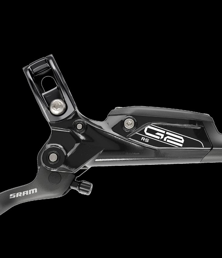
G2 RS, G2 R

SERVICE MANUAL

                 GEN.0000000006205 Rev B © 2021 SRAM, LLC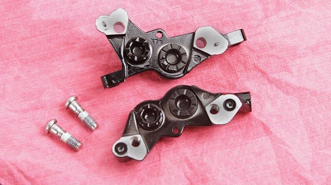
SRAM® LLC WARRANTY
THIS WARRANTY GIVES YOU SPECIFIC LEGAL RIGHTS AGAINST SRAM, LLC. YOU MAY ALSO HAVE OTHER RIGHTS THAT VARY FROM
STATE TO STATE, COUNTRY, OR PROVINCE. THIS WARRANTY DOES NOT AFFECT YOUR STATUTORY RIGHTS. TO THE EXTENT THIS
WARRANTY IS INCONSISTENT WITH THE LOCAL LAW, THIS WARRANTY SHALL BE DEEMED MODIFIED TO BE CONSISTENT WITH SUCH
LAW. FOR A FULL UNDERSTANDING OF YOUR RIGHTS, CONSULT THE LAWS OF YOUR COUNTRY, PROVINCE, OR STATE.
EXTENT OF LIMITED WARRANTY
Except as otherwise set forth herein, SRAM warrants its bicycle components to be free from defects in materials or workmanship for a period of two
(2) years after original purchase of the product.
SRAM warrants all Zipp MOTO Wheels and Rims to be free from defects in materials or workmanship for the lifetime of the product.
SRAM warrants all non-electronic Zipp branded bicycle components, Model Year 2021 or newer, to be free from defects in materials or workmanship
for the lifetime of the product.
GENERAL PROVISIONS
This warranty only applies to the original owner and is not transferable. Claims under this warranty must be made through the retailer where the
bicycle or the SRAM product was purchased or a SRAM authorized service location. Original proof of purchase is required. All SRAM warranty claims
will be evaluated by a SRAM authorized service location whereupon acceptance of the claim the product will be repaired, replaced, or refunded at
SRAM's discretion. To the extent allowed by local law claims under this warranty must be made during the warranty period and within one (1) year
following the date on which any such claim arises.
NO OTHER WARRANTIES
EXCEPT AS DESCRIBED HEREIN, AND TO THE EXTENT ALLOWED BY LOCAL LAW, SRAM MAKES NO OTHER WARRANTIES, GUARANTIES, OR
REPRESENTATIONS OF ANY TYPE (EXPRESS OR IMPLIED), AND ALL WARRANTIES (INCLUDING ANY IMPLIED WARRANTIES OF REASONABLE
CARE, MERCHANTABILITY, OR FITNESS FOR A PARTICULAR PURPOSE) ARE HEREBY DISCLAIMED.
LIMITATIONS OF LIABILITY
EXCEPT AS DESCRIBED HEREIN, AND TO THE EXTENT PERMITTED BY LAW, IN NO EVENT SHALL SRAM OR ITS THIRD PARTY SUPPLIERS BE
LIABLE FOR DIRECT, INDIRECT, SPECIAL, INCIDENTAL, OR CONSEQUENTIAL DAMAGES. SOME STATES (COUNTRIES AND PROVINCES) DO NOT
ALLOW THE EXCLUSION OR LIMITATION OF INCIDENTAL DAMAGES, SO THE ABOVE LIMITATION MAY NOT APPLY TO YOU.
LIMITATIONS OF WARRANTY
This warranty does not apply to products that have been incorrectly installed, adjusted, and/or maintained according to the respective SRAM user
manual. The SRAM user manuals can be found online at sram.com/service.
This warranty does not apply to damage to the product caused by a crash, impact, abuse of the product, non-compliance with manufacturer's
specifications of intended usage, or any other circumstances in which the product has been subjected to forces or loads beyond its design.
This warranty does not apply when the product has been modified, including but not limited to, any attempt to open or repair any electronic and
electronic related components, including the motor, controller, battery packs, wiring harnesses, switches, and chargers.
This warranty does not apply when the serial number or production code has been deliberately altered, defaced, or removed.
SRAM components are designed for use only on bicycles that are pedal powered or pedal assisted (e-Bike/Pedelec).
Notwithstanding anything else set forth herein, the battery pack and charger warranty does not include damage from power surges, use of improper
charger, improper maintenance, or such other misuse.
This warranty shall not cover damages caused by the use of parts of different manufacturers or parts that are not compatible or suitable for use with
SRAM components.
This warranty shall not cover damages resulting from commercial (rental) use.
WEAR AND TEAR
This warranty does not apply to normal wear and tear. Wear and tear parts are subject to damage as a result of normal use, failure to service
according to SRAM recommendations, and/or riding or installation in conditions or applications other than recommended.
WEAR AND TEAR PARTS INCLUDE:
• Aero bar pads            • Chains                                        • Rear shock mounting                 • Stripped threads/bolts (aluminum,
• Air sealing o-rings      • Corrosion                                       hardware and main seals               titanium, magnesium or steel)
• Batteries                • Disc brake rotors                             • Rubber moving parts                 • Tires
• Bearings                 • Dust seals                                    • Shifter and Brake cables            • Tools
• Bottomout pads           • Free hubs, Driver bodies, Pawls                 (inner and outer)                   • Transmission gears
• Brake pads               • Foam rings, Glide rings                       • Shifter grips                       • Upper tubes (stanchions)
• Bushings                 • Handlebar grips                               • Spokes                              • Wheel braking surfaces
• Cassettes                • Jockey wheels                                 • Sprockets
ZIPP IMPACT REPLACEMENT POLICY
Zipp branded products, Model Year 2021 or newer, are covered under a lifetime impact-damage replacement policy. This policy can be used to obtain
a replacement of a product in the event of non-warranty impact damage occurring while riding your bicycle. See www.zipp.com/support for more
information.

                                                                                                                                                       2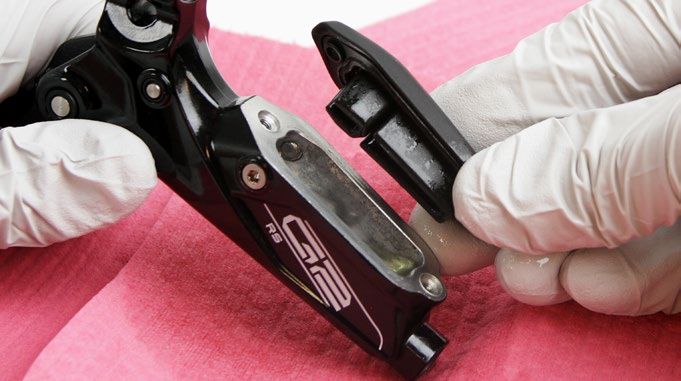
SAFETY FIRST!
We care about YOU. Please, always wear your safety glasses
  and protective gloves when servicing SRAM® products.
          Protect yourself! Wear your safety gear!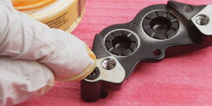
TABLE OF CONTENTS
SRAM G2 BRAKE SYSTEMS SERVICE...............................................................................................................................................................5
       SERVICE PROCEDURES..................................................................................................................................................................................................................................6

TROUBLESHOOTING...........................................................................................................................................................................................7

CALIPER SERVICE..............................................................................................................................................................................................10
       PARTS AND TOOLS NEEDED FOR SERVICE......................................................................................................................................................................................... 10
       CALIPER EXPLODED VIEW.......................................................................................................................................................................................................................... 10
       CALIPER BRAKE PAD REMOVAL................................................................................................................................................................................................................. 11
       CALIPER PISTON REMOVAL........................................................................................................................................................................................................................ 12
       CALIPER PISTON INSTALLATION.............................................................................................................................................................................................................. 16
       CALIPER BRAKE HOSE INSTALLATION................................................................................................................................................................................................... 18

LEVER SERVICE................................................................................................................................................................................................. 20
       PARTS AND TOOLS NEEDED FOR SERVICE........................................................................................................................................................................................ 20
       G2 RS LEVER EXPLODED VIEW................................................................................................................................................................................................................ 20
       G2 R LEVER EXPLODED VIEW................................................................................................................................................................................................................... 20
       LEVER FLUID REMOVAL............................................................................................................................................................................................................................... 21
       LEVER BLADE REMOVAL............................................................................................................................................................................................................................ 24
       PISTON ASSEMBLY REMOVAL.................................................................................................................................................................................................................. 25
       PISTON ASSEMBLY INSTALLATION......................................................................................................................................................................................................... 27
       RS LEVER BLADE INSTALLATION............................................................................................................................................................................................................. 28
       R LEVER BLADE INSTALLATION............................................................................................................................................................................................................... 30
       RESERVOIR CAP INSTALLATION.............................................................................................................................................................................................................. 32
       LEVER BRAKE HOSE INSTALLATION...................................................................................................................................................................................................... 33

DISC BRAKE PAD AND ROTOR BED-IN PROCEDURE................................................................................................................................ 35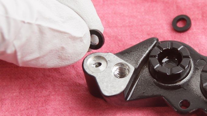
SRAM G2 Brake Systems Service
We recommend that you have your SRAM G2 components serviced by a qualified bicycle mechanic. Servicing SRAM components requires knowledge
of bicycle mechanics as well as the special tools and lubricants/fluids used for service.
SRAM brake systems need to be serviced periodically to optimize braking function. If brake fluid is leaking from any area of the brake there may be
damage or wear and tear to the internal moving parts. If the system has been contaminated with the wrong fluid there may be damage to all rubber
and plastic internal parts. If your brake was damaged in a crash there may be damage to the lever blade, pushrod, and housing assemblies. Inspect
and replace these parts to restore proper brake function.
Visit www.sram.com/service for the latest SRAM Spare Parts catalog and technical information. For order information, please contact your local SRAM
distributor or dealer.
      For recycling and environmental compliance information, please visit www.sram.com/company/environment.
Information contained in this publication is subject to change at any time without prior notice. Your product's appearance may differ from the pictures
contained in this publication.

                                                         SAFETY INSTRUCTIONS
 Do not use mineral oil or DOT 5 fluid.
 If the brake system has been contaminated with mineral oil or DOT 5 fluid, flush all of the parts with soapy water, rinse them with clean water, then
 allow all the parts to dry prior to rebuilding. Install new seals, a new bladder, and replace the hose.
 For best results, use only SRAM High-Performance DOT 5.1 brake fluid. If SRAM brake fluid is not available, only use DOT 5.1 or 4 brake fluid.
 Use only DOT compatible grease.
 Always wear safety glasses and nitrile gloves when working with DOT brake fluid.
 Used DOT brake fluid should be recycled or disposed of in accordance to local and federal regulations.
 Never pour DOT brake fluid down a sewage or drainage system or into the ground or a body of water.
 Do not allow any brake fluid to come in contact with the brake pads. If this occurs, the pads are contaminated and must be replaced.
 Place an oil pan on the floor underneath the area where you will be working on the brake.
 Servicing your brakes removes all of the brake fluid from the system. You must bleed your brakes after you service the brake system. Consult the
 SRAM MTB Disc Brake Hose Shortening and Bleed Manual at www.sram.com/service.

                                                                   ⚠CAUTION
 Do not use mineral oil or DOT 5 fluid. Do not use tools, rags, or syringes that are contaminated with mineral oil or DOT 5 fluid. Using contaminated
 materials will result in permanent damage to the seals and reduce braking performance. Brakes must be replaced if contaminated with mineral oil
 or DOT 5 fluid.

                                                                      NOTICE
 The G2 caliper must be serviced before the lever. The lever must be connected to the caliper and the brakes must still have fluid in them in order to
 advance the pistons and service the caliper. Once the lever has been disconnected and the fluid drained it is not possible to advance the pistons.

                                                                                                                SRAM G2 Brake Systems Service            5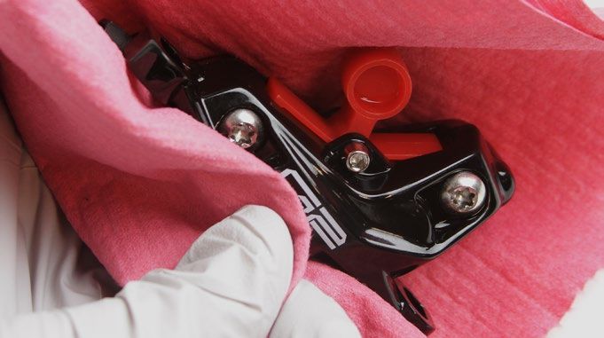
Service Procedures
The following procedures should be performed throughout service, unless otherwise specified.
Clean the part with isopropyl alcohol and a clean, lint-free shop towel.
Clean the sealing surface on the part and inspect it for scratches.

Replace the o-ring or seal with a new one from the service kit. Use your
fingers, a ziptie, or a pick to pierce and remove the old seal or o-ring.
Apply DOT grease to the new seal or o-ring when instructed.

                                  NOTICE
 Do not scratch any sealing surfaces when servicing the product. Scratches
 can cause leaks. Consult the spare parts catalog to replace the damaged
 part.
 Do not apply grease to the caliper piston seals. Grease on the seals will
 reduce the clearance gap between the pads and rotors when the brake is
 released (low pad rollback).

Use aluminum soft jaws when placing a part in a bench vise.
Tighten the part with a torque wrench to the torque value listed in the red bar.
When using a crowfoot socket and torque wrench, install the crowfoot socket
at 90 degrees to the torque wrench.

                                                                                               Specified torque value in N·m (in-lb)

                                                                                                   Service Procedures                  6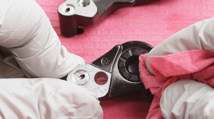
Tr o u b l e s h o o t i n g
                                                                     NOTICE
 Do not apply DOT brake fluid or grease to caliper pistons when performing troubleshooting procedures. Use of DOT brake fluid or grease can
 diminish braking performance and cause rotor rubbing.

If your brakes exhibit excessive lever throw or spongy feel, perform the following steps before bleeding the system:

 1    Clamp the bicycle into a bicycle work stand.
      Remove the wheel from the affected caliper.

 2    Remove the E-clip from the pad retention bolt.
      Remove the pad retention bolt from the caliper.

                                                                                   Needle nose pliers                  2.5 mm

 3    Remove the brake pads and pad H-spring from the caliper.

 4    Insert two brake rotors into the caliper rotor slot.

                                                                                                                                Troubleshooting   7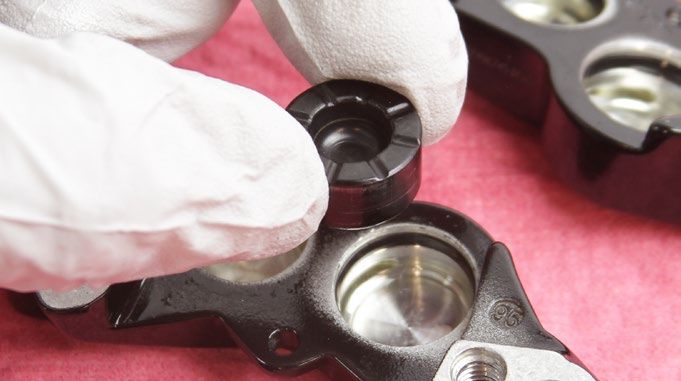
5   Squeeze the brake lever to advance the pistons until they contact the
    rotors.
    Remove the rotors.

6   Use a plastic tire lever to carefully press the pistons back into the
    caliper.
    Repeat steps 4-6 one more time.

7   With the pistons pressed back into the caliper, install the brake pads,
    h-spring, pad retention bolt, and E-clip.

8   Install the wheel.

                                                                              Troubleshooting   8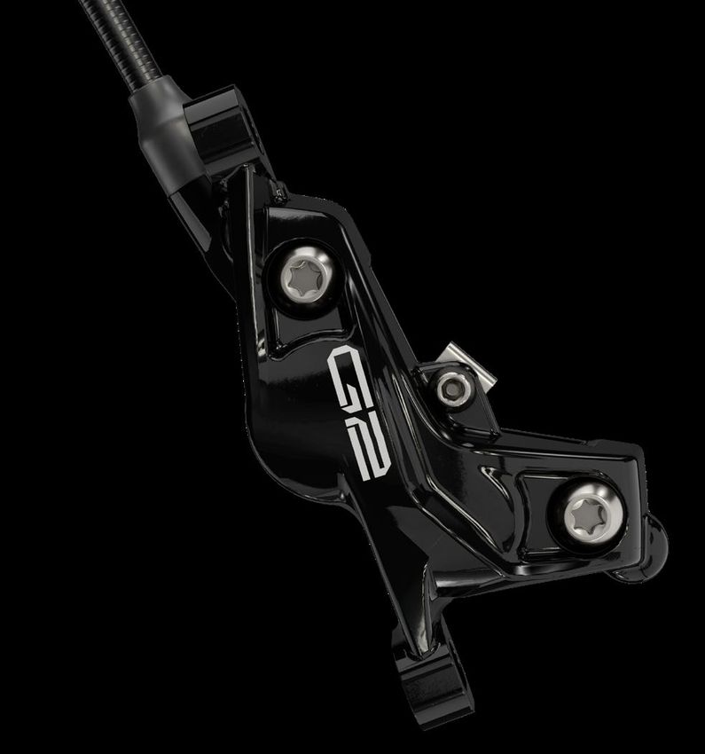
9   Squeeze the brake lever until the contact point is firm and lever throw
    is acceptable.
    Center the caliper on the rotor if necessary.
    Spin the wheel and check the brake function. The pistons should move
    freely and there should not be excessive brake lever throw.
    If there is no improvement in the brake function, perform a brake bleed.

                                                                               Troubleshooting   9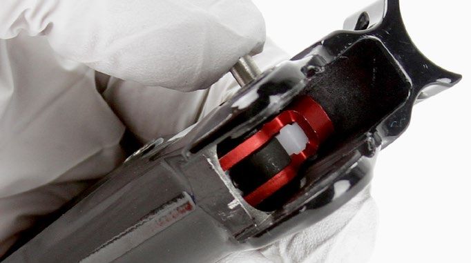
Caliper Service

 P a r t s a n d To o l s N e e d e d f o r S e r v i c e
   Parts                                                                       Common Tools
   • SRAM Guide / G2 Brake Pad Kit                                             • 2.5 mm hex wrench
   • Disc Brake Caliper Piston Kit - (Includes 2-16 mm & 2-14 mm Caliper       • Needle nose pliers
     Pistons, Seals & O-Rings) - Guide R, RS, RSC (A1-B1), G2 RSC/Ultimate
                                                                               • Pick with a 90 degree bent tip
   Safety and Protection Supplies                                              • T25 TORX wrench
   • Safety glasses                                                            • T25 TORX bit socket
   • Nitrile gloves                                                            • Torque wrench
   • Oil pan                                                                   • Digital caliper
   • Clean, lint-free shop towel
                                                                               SRAM Tools
   Lubricants and Fluids                                                       • SRAM Brake Bleed Kit (includes Bleed Block and Bleeding
   • Isopropyl alcohol                                                           Edge Fitting)
   • SRAM High-Performance DOT 5.1 brake fluid. If SRAM fluid is not           • SRAM Hydraulic Hose Cutter
     available, only use DOT 5.1 or 4 brake fluid.                             • Pad Spacer Tool (1.85 mm)
   • SRAM or AVID DOT grease. If SRAM or AVID DOT grease is not
     available only use a DOT compatible grease.

• For piston removal you will need two used brake rotors with a combined total thickness of no more than 3.7 mm.

 Caliper Exploded View

                                                                       Pad retention bolt
                                                                                                             Bleed block (medium)
                  Caliper body bolt (2)        Outboard
                                               caliper body
                                                                                        Pad H-Spring

                                                              Brake pad (2)

                                                                          Caliper pistons              E-clip
                                                                          16 mm (2)
                                                                                                                                    Compression
           Caliper o-ring (2)                                                        Piston seals                                   nut boot
                                                                                     16 mm (2)                              Compression nut
                                                                                                                     Hose
                                                                                                                Hose barb
                                                                                                          Compression fitting

                                   Caliper pistons
 Pad Spacer (1.85 mm)                   14 mm (2)

                                                 Piston seals
                                                    14 mm (2)

                                                                                                             Inboard
                                                                                                             caliper body

                                                                  Bleed screw port                      Bleed port plug (RS only)

                                                                                                                                Caliper Service   10
Caliper Brake Pad Removal
1 Remove the brake caliper from the fork or frame.
Remove the caliper mounting bracket and hardware from the caliper
then set them aside in the order that they were removed.
2 Use needle nose pliers to remove the E-clip from the pad retention
bolt.
Remove the pad retention bolt from the caliper.
Needle nose pliers 2.5 mm
3 Remove the brake pads and pad h-spring from the caliper.
NOTICE
Brake pads must be replaced if the total thickness of the backing
plate and pad friction material is less than 3 mm.
Digital Caliper
Caliper Brake Pad Removal 11NOTICE
Caliper service is only required if the pistons are damaged or if the system has been contaminated with DOT 5 or mineral oil.
If the calipers are operating normally, they do not require disassembly and service. Clean the calipers and install brake pads.
Caliper Piston Removal
NOTICE
DOT brake fluid will damage painted surfaces. If any fluid comes in contact with a painted surface (i.e. your frame) or printing on the brakes, wipe
it off immediately and clean it with isopropyl alcohol or water. Damage to painted and/or printed surfaces by DOT brake fluid is not covered under
warranty.
1 Insert two brake rotors into the caliper and into the rotor slot.
2 Squeeze the brake lever to advance the pistons until they contact the
rotors.
Remove the rotors.
Caliper Piston Removal 123 Install the pad retention bolt.
Insert the pad spacer so that it snaps onto the pad retention bolt.
2.5 mm 1.85 mm pad spacer
4 Squeeze the brake lever to advance the pistons until they contact the
pad spacer.
5 Remove the pad spacer.
Remove the pad retention bolt.
2.5 mm
Caliper Piston Removal 136 Pull the rubber boot from the compression nut.
7 Disconnect the brake hose from the caliper body.
8 mm flare nut wrench
8 Remove each caliper body bolt.
T25
9 Separate the caliper body halves.
Caliper Piston Removal 1410 Remove both of the caliper o-rings from the inboard side of the caliper.
11 Remove the pistons from each caliper body half.
NOTICE
If it is not possible to remove the pistions by hand, soft-jawed pliers
may be used to carefully remove the pistons.
12 Remove the piston seals from each caliper body half. Install new seals
inside each caliper body half.
⚠WARNING
Do not scratch the seal gland with the pick. Scratches could cause
fluid to leak when the brake is applied, which will contaminate the
brake pads and could lead to a brake failure.
NOTICE
Do not apply grease to the caliper piston seals. Grease on the seals
will reduce the clearance between the pads and rotors when the
brake is released (low pad rollback).
Pick
Caliper Piston Removal 15Caliper Piston Installation
NOTICE
DOT brake fluid will damage painted surfaces. If any fluid comes in contact with a painted surface (i.e. your frame) or printing on the brakes, wipe
it off immediately and clean it with isopropyl alcohol or water. Damage to painted and/or printed surfaces by DOT brake fluid is not covered under
warranty.
1 Inspect the caliper pistons for damage and replace the pistons if
necessary.
Apply a small amount of SRAM High-Performance DOT 5.1 brake fluid
to the circumference of each piston and seals. Install the pistons into
each half of the caliper body.
NOTICE
For the best braking performance, use only SRAM High-Performance
DOT 5.1 brake fluid. If SRAM fluid is not available, use only DOT 5.1 or
4 brake fluid. Do not apply grease to the caliper piston seals. Grease
on the seals will reduce the clearance between the pads and rotors
when the brake is released (low pad rollback).
SRAM High-Performance DOT 5.1
brake fluid
2 Spray isopropyl alcohol on the caliper halves and both of your gloves,
and clean them with a shop towel.
3 Apply a small amount of DOT grease to the new caliper o-rings and
install them onto the outboard caliper half.
DOT Grease
4 Align the caliper body halves then thread each body bolt into the
caliper.
Tighten each bolt to 11.5 N·m (101.5 in-lb).
T25 11.5 N·m (101.5 in-lb)
Caliper Piston Installation 165 Insert the bleed block into the caliper.
Bleed block
6 Install the pad retention bolt.
⚠WARNING
You must bleed your brakes before reinstalling the brake pads.
Installing the brake pads prior to bleeding the brakes could
contaminate the brake pads and lead to a brake failure.
2.5 mm
Caliper Piston Installation 17Caliper Brake Hose Installation
1 Slide the lever hose boot and compression nut away from the
compression fitting.
2 At the caliper end of the hose, cut the hose to install a new barb and
compression fitting.
NOTICE
You must install a new hose barb and compression fitting before
connecting the hose to the caliper.
SRAM Hydraulic Hose Cutter
4
3 Apply DOT grease to the hose barb threads. Thread the hose barb into
the hose until it is flush with the end of the hose.
NOTICE
Do not overtighten the hose barb. Overtightening may cause damage
to the hose liner.
T8 T8
5 Thread the compression fitting over the hose barb, counter-clockwise,
until it is flush or slightly lower than the hose barb.
The compression fitting is reverse threaded.
Apply DOT grease to the outside of the compression fitting and the
threads of the compression nut.
DOT grease
Caliper Brake Hose Installation 186 Insert the compression fitting and hose into the caliper.
Tighten the compression nut.
8 mm flare nut wrench 8 N·m (71 in-lb)
7 Install the rubber boot onto the compression nut.
8 Spray isopropyl alcohol on the caliper and clean it with a shop towel.
⚠CAUTION
Servicing your brakes removes all of the fluid from the system. You must bleed the brakes after you service the brake caliper and/or lever.
For brake bleed and brake hose shortening instructions, visit www.sram.com/service.
Caliper Brake Hose Installation 19Lever Service
P a r t s a n d To o l s N e e d e d f o r S e r v i c e
Parts Common Tools
• Lever Internals Guide™ RS or Lever Internals Guide R/RE / DB5™ / • Needle nose pliers
Code™ R
• Pick with a 90 degree bent tip
Safety and Protection Supplies • Internal snap ring pliers
• Safety glasses • T8, T10, & T25 TORX wrench
• Nitrile gloves • T10 TORX bit socket
• Oil pan • 8 mm flare nut crowfoot wrench
• Clean, lint-free shop towels • 2.5, 3, 4, & 6 mm hex wrenches
Lubricants and Fluids • 6 mm socket
• Isopropyl alcohol • Torque wrench
• SRAM High-Performance DOT 5.1 brake fluid. If SRAM fluid is not • Hammer
available, only use DOT 5.1 or 4 brake fluid.
SRAM Tools
• SRAM or AVID DOT grease. If SRAM or AVID DOT grease is not
available only use a DOT compatible grease. • SRAM Hydraulic Hose Cutter
G2 RS Lever Exploded View
Reservoir bolts (2)
SwingLink bushings (2) SwingLink push rod
SwingLink pivot pin SwingLink
Reservoir cap
Lever bias spring
Bladder
Hose Hose barb
Lever body Cam bushing
Main pivot clip
Hose boot
Bleed Lever
Compression nut assembly
port (2) Piston assembly
Compression fitting
SwingLink Lever
pivot hole pivot hole Washer Lever pivot pin
Bleed port screw o-ring (2) Snap ring
Bleed port screw (2) Lever pivot bushings (2)
G2 R Lever Exploded View
Reservoir bolts (2)
Lever bias spring
Reservoir cap
Pushrod
Bladder
Hose Hose barb
Lever body Cam bushing
Main pivot clip
Hose boot
Bleed Lever
Compression nut assembly
port (2) Piston assembly
Compression fitting
Lever
pivot hole Washer Lever pivot pin
Bleed port screw o-ring (2) Snap ring
Bleed port screw (2) Lever pivot bushings (2)
Lever Service 20Lever Fluid Removal
NOTICE
DOT brake fluid will damage painted surfaces. If any fluid comes in contact with a painted surface (i.e. your frame) or printing on the brakes, wipe
it off immediately and clean it with isopropyl alcohol or water. Damage to painted and/or printed surfaces by DOT brake fluid is not covered under
warranty.
1 Use a T25 TORX wrench or a 4 mm hex wrench to remove the brake
clamp bolt from the discrete clamp, MMX, or XLoc (XLoc requires
removal of the shifter) and remove the brake lever from the handlebar.
2 Pull the hose boot off the compression nut and slide it down the hose.
3 Remove the hose compression nut.
Pull the brake hose and compression fitting from the brake lever body.
8 mm
4 Pour the brake fluid into an oil pan. Squeeze the lever blade to pump
out the excess brake fluid from inside the lever body.
NOTICE
If the system has been contaminated with mineral oil or DOT 5 fluid,
flush all the parts with soapy water, rinse, and allow all parts to dry
prior to rebuilding. Install new seals and a new hose.
For best results, use only SRAM High-Performance DOT 5.1 brake
fluid. If SRAM fluid is not available, only use DOT 5.1 or 4 brake fluid.
Lever Fluid Removal 215 Remove the reservoir cap bolts.
T10 T10
6 Remove the reservoir cover and bladder from the lever body.
7 Pour the fluid from the brake lever body into a pan.
8 Remove the two bleed screws.
Install new o-rings and install the bleed screws into the lever body.
T10
Lever Fluid Removal 229 Separate the bladder from the reservoir cover.
Spray isopropyl alcohol on the bladder and the reservoir cover and
clean them with a shop towel.
NOTICE
All components must be completely dry before reinstalling them.
Moisture residue from cleaning the bladder can leak out of the
bladder as it dries, which can be misinterpreted as a system leak.
Lever Fluid Removal 23Lever Blade Removal
1 Place the lever pivot on top of a 6 mm socket. Tap a 4 mm hex wrench
with a hammer to remove the pivot pin.
4 mm 6 mm socket 4 mm
2 Remove the lever blade.
The lever assembly will separate into four pieces when removed from
the lever body: SwingLink cam, lever bias spring, main pivot clip, and
blade assembly.
G2 RS G2 RS
G2 R G2 R
3 Remove the pivot bushings. Clean the bushings and install them into
the lever body.
6 mm
Lever Blade Removal 24Piston Assembly Removal
1 Push the SwingLink pivot pin out of the lever body.
3 mm
2 Remove the SwingLink.
RS
3 Remove the SwingLink bushings.
4 mm
4 Use long-tipped internal snap ring pliers to apply downward pressure
to the lever body and remove the snap ring.
Turn the lever body upside down to allow the washer to fall out of the
body.
⚠CAUTION - EYE HAZARD
Wear safety glasses. Do not look directly into the lever body while
performing this step. The internal piston/spring assembly is preloaded
and will come out of the lever body quickly, which can result in injury.
internal snap ring pliers
Piston Assembly Removal 255 Use needle nose pliers to remove the piston assembly.
Needle nose pliers
Piston Assembly Removal 26Piston Assembly Installation
NOTICE
DOT brake fluid will damage painted surfaces. If any fluid comes in contact with a painted surface (i.e. your frame) or printing on the brakes, wipe
it off immediately and clean it with isopropyl alcohol or water. Damage to painted and/or printed surfaces by DOT brake fluid is not covered under
warranty.
1 Submerge the new piston assembly in SRAM High-Performance
DOT 5.1 brake fluid.
You can also use SRAM DOT Assembly Grease, or DOT 5.1 or 4
compatible grease, as a lubricant.
SRAM High-Performance DOT 5.1 brake fluid
2 Install the new lubricated piston assembly into the lever body.
3 lnstall the washer on the piston assembly.
Use long-tipped internal snap ring pliers to push the piston assembly
into the lever body, and secure the snap ring in its groove. Orient the
snap ring eyelets opposite the opening in the lever body.
internal snap ring pliers
Piston Assembly Installation 27RS Lever Blade Installation
1 Use needle nose pliers to install the SwingLink bushings.
If the SwingLink bushings fall out easily, apply a small amount of DOT
grease to the bushings to help hold them in place.
Needle nose pliers
2 Place the SwingLink pushrod into the piston.
RS
3 Line up the hole in the SwingLink with the hole in the bushings, then
push the pivot pin into the hole until it stops.
RS Lever Blade Installation 284 Hold the spring and main pivot clip in place while installing the lever
blade. Insert the reach adjust screw pin into the cam hole.
5 Line up the cam and lever blade with the holes in the lever body, then
press the pivot pin through the holes.
Use a hammer to gently tap the pivot pin into the pivot hole.
Hammer
Make sure the lever bias spring is seated properly in the lever. The
outboard end of the spring must press against the lever blade, while
the inboard end of the spring must press against the lever body. If the
return spring is not seated properly, you will not be able to adjust the
reach of the lever blade.
RS Lever Blade Installation 29R Lever Blade Installation
1 Hold the spring and main pivot clip in place while installing the lever
blade. Insert the Reach Adjust Screw pin into the cam hole.
2 Insert the pushrod into the piston.
R Lever Blade Installation 303 Line up the cam and lever blade with the holes in the lever body, then
press the pivot pin through the holes.
Use a hammer to gently tap the pivot pin into the pivot hole.
Hammer
Make sure the lever return spring is seated properly in the lever. The
outboard end of the spring must press against the lever blade, while
the inboard end of the spring must press against the lever body. If the
return spring is not seated properly, you will not be able to adjust the
reach of the lever blade.
R Lever Blade Installation 31Reservoir Cap Installation
1 Press the bladder into the reservoir cap, make sure the bladder is
properly seated into the reservoir cap. The bladder should be flush
with the cap.
2 Insert the reservoir cap/bladder assembly onto the lever body.
3 Use a torque wrench and a T10 TORX bit socket to tighten each
reservoir cap bolt to 1.2 N·m (10.5 in-lb).
T10 1.2 N•m (10.5 in-lb)
Reservoir Cap Installation 32Lever Brake Hose Installation
1 Slide the lever hose boot and compression nut away from the
compression fitting.
2 Cut the hose to install a new barb and compression fitting.
NOTICE
You must install a new hose barb and compression fitting before
connecting the hose to the brake lever.
SRAM Hydraulic Hose Cutter
5
4
3 Apply DOT grease to the hose barb threads. Thread the hose barb into
the hose until it is flush with the end of the hose.
NOTICE
Do not overtighten the hose barb. Overtightening may cause damage
to the hose liner.
T8 T8
6 Thread the compression fitting over the hose barb, counter-clockwise,
until it is flush or slightly lower than the hose barb.
The compression fitting is reverse threaded.
Apply DOT grease to the outside of the compression fitting and the
threads of the compression nut.Install the compression fitting and nut
into the lever.
DOT grease
Lever Brake Hose Installation 337 Use a flare nut crowfoot with a torque wrench to tighten the
compression nut to 8 N·m (71 in-lb).
Spray isopropyl alcohol on the lever body and clean it with a shop
towel.
Slide the hose boot onto the lever.
8 mm flare nut wrench 8 N·m (71 in-lb)
⚠CAUTION
Servicing your brakes removes all of the fluid from the system. You must bleed the brakes after you service the brake caliper and/or lever.
For brake bleed, brake hose shortening, and brake pad replacement instructions, visit www.sram.com/service.
Lever Brake Hose Installation 34Disc Brake Pad and Rotor Bed-in Procedure
All new brake pads and rotors should be put through a wear-in process called 'bed-in'. The bed-in procedure, which should be performed prior to your
first ride, ensures the most consistent and powerful braking feel along with the quietest braking in most riding conditions. The bed-in process heats
up the brake pads and rotors, which deposits an even layer of brake pad material (transfer layer) to the braking surface of the rotor. This transfer layer
optimizes braking performance. To watch a video of the bed-in procedure, visit www.sram.com/service.
⚠WARNING- CRASH HAZARD
The bed-in process requires you to perform heavy braking. You must be familiar with the power and operation of disc brakes. Braking heavily
when not familiar with the power and operation of disc brakes could cause you to crash, which could lead to serious injury and/or death. If you are
unfamiliar with the power and operation of disc brakes, you should have the bed-in process performed by a qualified bicycle mechanic.
To safely achieve optimal results, remain seated on the bike during the entire bed-in procedure. Do not lock up the wheels at any point during the
bed-in procedure.
• Accelerate the bike to a moderate speed, then firmly apply the brakes until you are at walking speed. Repeat approximately twenty times.
• Accelerate the bike to a faster speed, then very firmly apply the brakes until you are at walking speed. Repeat approximately ten times.
• Allow the brakes to cool prior to any additional riding.
• After the bed-in procedure has been performed, the caliper may need to be re-centered.
Disc Brake Pad and Rotor Bed-in Procedure 35These are registered trademarks of SRAM, LLC: 1:1®, Accuwatt®, Avid®, AXS®, Bar®, Blackbox®, BoXXer®, DoubleTap®, Elita®, eTap®, Firecrest®, Firex®, Grip Shift®, GXP®, Hammerschmidt®, Holzfeller®, Hussefelt®, i‑Motion®, Judy®, Know Your Powers®, NSW®, Omnium®, Pike®, PowerCal®, PowerLock®, PowerTap®, Qollector®, Quarq®, RacerMate®, Reba®, Rock Shox®, Ruktion®, Service Course®, ShockWiz®, SID®, Single Digit®, Speed Dial®, Speed Weaponry®, Spinscan®, SRAM®, SRAM APEX®, SRAM EAGLE®, SRAM FORCE®, SRAM RED®, SRAM RIVAL®, SRAM VIA®, Stylo®, Torpedo®, Truvativ®, TyreWiz®, Varicrank®, Velotron®, X0®, X01®, X‑SYNC®, XX1®, Zed tech®, Zipp® These are registered logos of SRAM, LLC: These are trademarks of SRAM, LLC: 10K™, 1X™, 202™, 30™, 35™, 302™, 303™, 404™, 454™, 808™, 858™, 3ZERO MOTO™ , ABLC™, AeroGlide™, AeroBalance™, AeroLink™, Airea™, Air Guides™, AKA™, AL‑7050‑TV™, Automatic Drive™, Automatix™, AxCad™, Axial Clutch™, BB5™, BB7™, BB30™, Bleeding Edge™, Blipbox™, BlipClamp™, BlipGrip™, Blips™, Bluto™, Bottomless Tokens™, Cage Lock™, Carbon Bridge™, Centera™, Charger 2™, Charger™, Charger Race Day™, Clickbox Technology™, Clics™, Code™, Cognition™, Connectamajig™, Counter Measure™, DD3™, DD3 Pulse™, DebonAir™, Deluxe™, Deluxe Re:Aktiv™, Descendant™, DFour™, DFour91™, Dig Valve™, DirectLink™, Direct Route™, DOT 5.1™, Double Decker™, Double Time™, Dual Flow Adjust™, Dual Position Air™, DUB™, DZero™, E300™, E400™, Eagle™, E‑Connect4™, E‑matic™, ErgoBlade™, ErgoDynamics™, ESP™, EX1™, Exact Actuation™, Exogram™, Flow Link™, FR‑5™, Full Pin™, Gnar Dog™, Guide™, GX™, Hard Chrome™, Hexfin™, HollowPin™, Howitzer™, HRD™, Hybrid Drive™, Hyperfoil™, i‑3™, Impress™, Jaws ™, Jet™, Kage™, Komfy™, Level™, Lyrik™, MatchMaker™, Maxle™, Maxle 360™, Maxle DH™, Maxle Lite™, Maxle Lite DH™, Maxle Stealth™, Maxle Ultimate™, Micro Gear System™, Mini Block™, Mini Cluster™, Monarch™, Monarch Plus™, Motion Control™, Motion Control DNA™, MRX™, Noir™, NX™, OCT™, OmniCal™, OneLoc™, Paragon™, PC‑1031™, PC‑1110 ™, PC‑1170™, PG‑1130™, PG‑1050™, PG‑1170™, Piggyback™, Poploc™, Power Balance™, Power Bulge™, PowerChain™, PowerDomeX™, Powered by SRAM™, PowerGlide™, PowerLink™, Power Pack™, Power Spline™, Predictive Steering™, Pressfit™, Pressfit 30™, Prime™, Qalvin™, R2C™, RAIL™, Rapid Recovery™, Re:Aktiv ThruShaft™, Recon™, Reverb™, Revelation™, Riken™, Rise™, ROAM™, Roller Bearing Clutch™, RS‑1™, Sag Gradients™, Sawtooth™, SCT ‑ Smart Coasterbrake Technology, Seeker™, Sektor™, SHIFT™, ShiftGuide™, Shorty™, Showstopper™, SIDLuxe™, Side Swap™, Signal Gear Technology™, SL™, SL‑70™, SL‑70 Aero™, SL‑70 Ergo™, SL‑80™, Sl‑88™, SLC2™, SL SPEED™, SL Sprint™, Smart Connect™, Solo Air™, Solo Spoke™, SpeedBall™, Speed Metal™, SRAM APEX 1™, SRAM Force 1™, SRAM RIVAL 1™, S‑series™, Stealth‑a‑majig ™, StealthRing™, Super‑9™, Supercork™, Super Deluxe™, Super Deluxe Coil™, SwingLink™, TaperCore™, Timing Port Closure™, Tool‑free Reach Adjust™, Top Loading Pads™, Torque Caps™, TRX™, Turnkey™, TwistLoc™, VCLC™, Vivid™, Vivid Air™, Vuka Aero™, Vuka Alumina™, Vuka Bull™, Vuka Clip™, Vuka Fit™, Wide Angle™, WiFLi™, X1™, X5™, X7™, X9™, X‑Actuation™, XC™, X‑Dome™, XD™, XD Driver Body™, XDR™, XG‑1150™, XG‑1175™, XG‑1180™, XG‑1190™, X‑Glide™, X‑GlideR™, X‑Horizon™, XLoc Sprint™, XX™, Yari™, ZEB™, Zero Loss™ Specifications and colors subject to change without prior notice. © 2021 SRAM, LLC This publication includes trademarks and registered trademarks of the following companies: TORX® is a registered trademark of Acument Intellectual Properties, LLC
ASIAN HEADQUARTERS                WORLD HEADQUARTERS                 EUROPEAN HEADQUARTERS
SRAM Taiwan                       SRAM LLC                           SRAM Europe
No. 1598-8 Chung Shan Road        1000 W. Fulton Market, 4th Floor   Paasbosweg 14-16
Shen Kang Hsiang, Taichung City   Chicago, Illinois 60607            3862ZS Nijkerk
Taiwan R.O.C.                     U.S.A.                             The Netherlands
You can also read