BIG BRAKE KIT INSTALLATION INSTRUCTIONS - Apollo-4 (100 Series)
←
→
Page content transcription
If your browser does not render page correctly, please read the page content below
BIG BRAKE KIT
INSTALLATION INSTRUCTIONS
Apollo-4 (100 Series)
BIG BRAKE KIT INSTALLATION
                                                           INSTRUCTIONS - Apollo-4 (100 Series)

Contents
1.  DISCLAIMER AND WARRANTY ................................................................................................. 2
2.  GENERAL AND SAFETY INFORMATION ....................................................................................... 4
3.  WHEEL CLEARANCE CHECK .................................................................................................... 5
4.  WHAT IS INCLUDED IN YOUR BIG BRAKE KIT? ............................................................................ 5
5.  GENERAL SYSTEM INFORMATION AND MAINTENANCE ................................................................. 5
6.  REMOVE FRONT BRAKING COMPONENTS.................................................................................. 5
7.  INSTALLATION OF NEW FRONT COMPONENTS............................................................................ 6
  7.1. Install Caliper Bracket. ............................................................................................. 6
  7.2. Install Disc and Bell Sub-assemblies......................................................................... 6
  7.3. Use a DTI gauge to measure disc run out. ............................................................... 6
  7.4. Install Front Brake Calipers ...................................................................................... 6
  7.5. Install front brake pads. ........................................................................................... 8
  7.6. Install front brake lines. ........................................................................................... 8
8. INSTALLATION OF NEW REAR COMPONENTS.............................................................................. 8
9. BRAKE BLEEDING PROCEDURE ................................................................................................ 9
10. LEAK TEST PROCEDURE ...................................................................................................... 9
11. MAIN BEDDING-IN PROCEDURE ........................................................................................ 10
12. ADDITIONAL INFORMATION .............................................................................................. 11
  12.1. Brake Pad Replacement ...................................................................................... 11
  12.2. Disc Replacement ............................................................................................... 11
  12.3. Cleaning of Calipers ............................................................................................ 11
  12.4. Brake Fluid .......................................................................................................... 11
  12.5. Assistance ........................................................................................................... 11

                                                                                                                    1|Page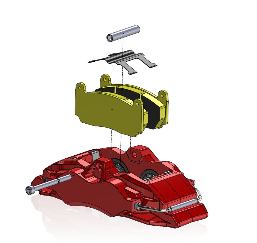
BIG BRAKE KIT INSTALLATION
                                                           INSTRUCTIONS - Apollo-4 (100 Series)

1. Disclaimer and Warranty

                                  WARNINGS AND DISCLAIMER
Although EBC Brakes Racing rigorously tests every product and makes every effort to ensure the supplied brake kit is
suitable for the vehicle for which it is listed, vehicle manufacturers can change the specification without warning and other
aftermarket modifications may prevent this brake kit from performing as intended*. For this reason, EBC Brakes and its
affiliates make no guarantees, either stated or implied, that the supplied parts are suitable for the vehicle to which they
are to be fitted. The purchaser expressly acknowledges, understands and agrees that they alone bear the full responsibility
for ensuring that the chosen product is suitable for their individual application and is fit for purpose.

Your vehicle’s brakes are a SAFETY CRITICAL system. Failure to install this product correctly could lead to poor braking
performance or potentially complete brake system failure, which may result in serious harm or death to yourself and
other persons.

The technical guidance set out in this instruction manual is intended to serve as a guide only and may not be an
exhaustive list of all the steps and considerations required to achieve a fully functioning and safe brake system. The
technical guidance set out in this instruction manual is intended to inform professional brake technicians who possess a
high level of competency in the installation of performance brake systems and adhere to safe general working practices
whilst working on vehicle brake systems. By proceeding to install or have installed the products contained herewith you
expressly acknowledge and agree to the aforementioned warnings and assume full liability for ensuring that the products
contained herewith are installed safely and are fit for purpose. EBC Brakes and its affiliates accept no liability for any
damages resulting from failure to observe any of the aforementioned warnings.

If you require further assistance and/or technical advice, please contact EBC Brakes directly and NOT the original reseller
who you purchased the product from. EBC Brakes have a dedicated technical team to assist you, however we ask that
allow up to 24 hours for a reply to account for global time zones. You can contact EBC technical by e-mailing:
kits@ebcbrakes.com

*The components supplied as part of this brake kit and the achieved brake bias has been carefully calculated to match with
the vehicles original master cylinder, original rear brake calipers and original rear brake discs. If you have modified your
vehicle significantly, e.g. fitted larger rear brake discs or a master cylinder with a different bore diameter, these
modifications may affect the brake bias and overall brake system performance. If in doubt contact EBC for further advice.

                                                                                                                 2|Page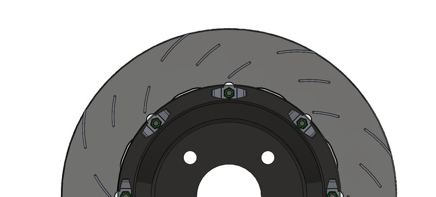
BIG BRAKE KIT INSTALLATION
                                                            INSTRUCTIONS - Apollo-4 (100 Series)

                                    DISCLAIMER OF WARRANTY
Freeman Automotive (UK) Limited t/a EBC Brakes Racing (“Manufacturer”) warrants to the original user that this Product
complies with our Manufacturer’s published specifications and is free from manufacturing defects in materials and
workmanship (a “Covered Defect”). EBC Brakes Racing offers the enclosed brake calipers with a Two (2) year warranty
against corrosion of metal components and against corrosion of the hard anodised aluminium caliper body. This 2 year
warranty does not apply to the coloured paint top coat. Take care not to collide with the caliper when removing/replacing
wheels to avoid chipping off the painted finish. This warranty is limited in duration to Two (2) years from the date of
purchase or such longer period required by law. In the event that a Covered Defect is claimed, a claim under this Limited
Warranty must be made in writing within sixty (60) days from its discovery or the date on which it ought to have been
discovered and within Two (2) years from the date of purchase, or within such longer period required by law. If the Product
is found to have a Covered Defect, the Product will be, in the Manufacturer’s sole judgment, either repaired or replaced by
a new or rebuilt Product.

For products sold in the U.S., some states do not allow the exclusion or limitation of incidental or consequential damages,
so one or more of the above limitations or exclusions may not apply to you. This Limited Warranty gives you specific legal
rights, and you may have other legal rights which vary from state to state. All claims under this Two-year Limited Warranty
must be made in writing within sixty (60) days following the discovery of the alleged Covered Defect and the claimed
defective Product or defective part(s) must be returned to Freeman Automotive (UK) Limited - EBC Brakes World
Headquarters, Upton Valley Way E, Upton, Pineham NN4 9EF through the distribution chain and transport prepaid, within
the Two-year warranty period, or within such longer period required by law. A statement of the defect must be included
with the Product or parts returned, and proof of purchase by the original user identifying the Product and date of purchase
(whether purchased at retail or sold by a dealer as part of the installation of the Product) must also be included.

This Limited Warranty does not apply to:
     •    Any damage to the Product caused in whole or in part by abuse, accident, fire, chemical corrosion, use for other
          than its intended purposes, unlawful use, use in a model for which it was not designed, faulty installation,
          installation contrary to the Manufacturer’s published instructions, or failure to maintain the Product in
          accordance with the Manufacturer’s published instructions.
     •    Any damage resulting from any type of motorsport/race use. Although this product has been tested and
          developed for moderate track use as well as on the public road, there is no warranty covering damage from the
          extreme variations/conditions in race disciplines.
     •    Claims relating to comfort, noise, vibration, or harsh operating characteristics.
     •    Claims made when repairs alterations or modifications have been made to the Product without the
          Manufacturer’s consent. This Limited Warranty sets forth the sole liability of Manufacturer hereunder, and it may
          not be changed by any employee, dealer, distributor of EBC Brakes Racing or any other person.

Although this product has been designed and manufactured for the specific model and application indicated in EBC Brakes
Racing catalogues or website (ebcbrakes.com), EBC Brakes Racing makes every effort to ensure the supplied brake kit is
suitable for the vehicle for which it is listed. Vehicle manufacturers can change the specification without warning and other
aftermarket modifications may prevent this brake kit from performing as intended*. For this reason, EBC Brakes and its
affiliates make no guarantees, either stated or implied, that the supplied parts are suitable for the vehicle to which they
are to be fitted. The purchaser expressly acknowledges, understands and agrees that they alone bear the full responsibility
for ensuring that the chosen product is suitable for their individual application, and is fit for purpose. The Product shall be
used in compliance with laws and rules in effect in the states and/or countries in which the vehicle in which the Product is
installed will be operated, including but not limited to compliance with the applicable traffic rules and obtaining any prior
necessary authorization/homologation, approval, or licence in such states and/or countries. The Manufacturer is relieved
of any and all damages, claims and liabilities in case the use of the Product does not comply with such applicable laws and
regulations.

By installing and using the Product the original user is deemed to have accepted the terms and conditions of this Limited
Warranty. This Limited Warranty shall be governed, construed, and interpreted in accordance with the laws of England.

**THIS LIMITED WARRANTY IS THE SOLE EXPRESS WARRANTY MADE WITH REGARD TO THIS PRODUCT SO FAR AS THE LAW
ALLOWS AND IS MADE IN LIEU OF ALL OTHER WARRANTIES WHETHER ORAL OR WRITTEN. ALL IMPLIED WARRANTIES,
INCLUDING, WITHOUT LIMITATION, WARRANTIES, OF MERCHANTABILITY OR FITNESS FOR A PARTICULAR PURPOSE, SHALL
BE LIMITED IN DURATION TO THE DURATION OF THIS WARRANTY. MANUFACTURER SHALL HAVE NO LIABILITY FOR
INCIDENTAL, OR CONSEQUENTIAL DAMAGES WHATSOEVER AND IN NO EVENT SHALL MANUFACTURER BE LIABLE FOR ANY
DAMAGES IN EXCESS OF CLAIMANT’S PURCHASE PRICE FOR THE PRODUCT.

                                                                                                                   3|Page
BIG BRAKE KIT INSTALLATION
INSTRUCTIONS - Apollo-4 (100 Series)
2. General and Safety Information
“DANGER!” means procedures which, if not observed, have a high degree of probability that they will cause
serious injury or even death.
“WARNING!” means procedures which, if not observed, could possibly cause injury.
“CAUTION!” means procedures which, if not observed, could result in damage to the vehicle.
• DANGER! This product is vital to the safe operation of the vehicle on which it is installed, and it is intended to be
installed only by a skilled, qualified individual EBC Brakes Racing shall not be liable for any damage or injury
caused to or by any person operating a vehicle on which a replacement product has been improperly installed. If
you require further assistance and/or technical advice, please contact EBC Brakes directly and NOT the original
reseller who you purchased the product from. EBC Brakes have a dedicated technical team to assist you, however
we ask that allow up to 24 hours for a reply to account for global time zones. You can contact EBC Brakes Racing
by e-mailing: kits@ebcbrakes.com
• WARNING! In the course of replacing the product, and related items such as brake fluid, brake pads, brake
shoes, and the like, the installer will be exposed to fluids and parts that may be deemed to be “hazardous waste”
under applicable laws, rules and regulations. All such wastes must be handled, recycled and/or disposed if in
accordance with all applicable laws, rules, and regulations. The failure to do so can subject the generator of the
hazardous waste to penalties under environmental laws and could result in bodily injury or property damage to
the generator or others.
• DANGER! Always check that the brake fluid level in the reservoir is between the minimum and maximum levels
indicated on the reservoir. An incorrect level can cause brake fluid leaks or reduced brake system efficiency. Too
much or too little brake fluid in the reservoir could cause the brakes not to perform properly, and personal injury,
including death, could result.
• CAUTION! To avoid creating a faulty installation, avoid sharply striking and/or damaging the product, its parts
and its components especially rubber components, as this can impair their efficiency and may cause them to
malfunction. If necessary, replace and damaged part or component.
• WARNING! To avoid injury: - Always wear gloves during disassembly and assembly of components with sharp
edges. - Do not allow skin surfaces to make direct contact between the pad and shoe linings since this could
cause abrasions. - Avoid direct contact with brake fluid as it can cause irritation to the skin and eyes. In the event
of contact, clean thoroughly in accordance with the vehicle or brake fluid manufacturer’s instructions. - Ensure
correct connection of any electrical contacts.
• DANGER! Avoid contact of grease and other lubricants with the braking surfaces of the discs, and pads as this
could affect the efficiency of the braking system and cause serious physical damage.
WARNING! The brake system is a safety device; personnel executing any replacement or maintenance
operations must be competent and certified. Your vehicle’s brakes are a SAFETY CRITICAL system. Failure to
install this product correctly could lead to poor braking performance or potentially complete brake system
failure, which may result in serious harm or death to yourself and other persons.
*The components supplied as part of this brake kit and the achieved brake bias has been carefully calculated to match with
the vehicles original master cylinder, original rear brake calipers and original rear brake discs. If you have modified your
vehicle significantly, e.g. fitted larger rear brake discs or a master cylinder with a different bore diameter, these
modifications may affect the brake bias and overall brake system performance. If in doubt, contact EBC for further advice.
** Pay great attention when installing a Big Brake Kit, in particular on second hand vehicles. Even if the bearings, all parts
of the suspension, bushes, heads, axles shaft, rims, tyres etc. Are not disproportionately worn after limited use, they must
be checked in accordance with the vehicle manufacturers manual and, if necessary, replace before installing a Big Brake Kit.
If the worn parts are not checked and replaced, the discs could be permanently damaged, with a consequential reduction in
performance and vibration on the steering wheel and/or on the brake pedal even only a short distance after installation.
4|PageBIG BRAKE KIT INSTALLATION
INSTRUCTIONS - Apollo-4 (100 Series)
3. Wheel Clearance Check
Before starting the installation of our kit make sure the brake upgrade is suitable for the make and model of
the vehicle. The fitment of brake upgrade kits can often lead to an increase in disc diameter and caliper width,
create wheel clearance issues. This clearance can be checked by using our detailed Wheel Clearance
Templates which are available from https://ebcbrakes.com/ebc-brakes-racing_downloads/
or by contacting EBC Brakes Racing.
BEFORE ATTEMPTING THIS INSTALL locate the wheel template, cut around it and then revolve it in your wheel
rim to check whether the upgraded brake system is likely to fit within your wheels. A minimum clearance of
3.0mm is mandatory. If the clearance is insufficient then the use or different wheels will be required as EBC
Brake Racing does not recommend the use of separate wheel spacers.
4. What is included in your Big Brake Kit?
- 2 x Apollo-4 (100 Series) Brake Calipers
- 2 x Fully Floating 2-piece brake discs (Marked L&R)
- 2 x EBC caliper brackets CNC machined from aerospace grade aluminum for high strength and are
then anodized to prevent against corrosion.
- 1 x Performance Brake Pads (Front axle set)
- 1 x Performance Brake Pads (Rear axle set)
- 4 x Stainless braided brake lines including: Front & Rear.
- 1 x 1 litre of BF307+ super DOT 4 brake fluid
- 1 x Vehicle specific upgrade package includes everything you need to fit the kit, including brackets,
bolts, washers, nuts, and spacers.
If there are any components missing from your kit that are listed above, please contact EBC Brakes Racing for
assistance.
5. General System Information and Maintenance
In addition to the usual components supplied typically in front axle big brake kits (calipers/discs/pads/lines),
EBC’s balanced big brake kits also include brake pads and brake lines for the rear axle to fit the original rear
brake caliper. By controlling the components fitted to both the front and rear axle an optimum brake balance
is achieved which leads to increased brake system performance and shorter overall stopping distances.
NOTE: Failure to install the rear axle components supplied as part of this kit may degrade system performance.
Allow between 3-5 hours for the install. Changing both the front and rear brake components will take longer
than a front axle only big brake kit. Do not rush the installation and follow the guidance set out in this
document carefully.
6. Remove Front Braking Components
6.1. Crack off front wheel nuts.
6.2. Jack up the vehicle and place securely on axle stands.
6.3. Remove front wheels.
6.4. Depress and wedge brake pedal fully down.
6.5. Detach mid-line bracket on flexi brake line*
6.6. Detach flexi brake line where it meets vehicle hardline*
6.7. Remove brake caliper*
6.8. Remove brake disc.
6.9. Remove/modify dust shield.
6.10. CLEAN UP THE HUB (Remove all rust from the hub using a wire brush or a light abrasive)
6.11. Clean bracket lugs
CAUTION! * Brake fluid will damage any painted surface. If brake fluid is spilled on any painted surface clean
with warm soapy water.
5|PageBIG BRAKE KIT INSTALLATION
INSTRUCTIONS - Apollo-4 (100 Series)
7. Installation of New Front Components
7.1. Install Caliper Bracket.
(Using the supplied M12 bolts and washers) Torque bolts to 100 Nm (74 Ft-lb)
* Mount the bracket to the same mount up face used by the original caliper. The bracket must be orientated
facing away from you.
7.2. Install Disc and Bell Sub-assemblies.
* Clean discs thoroughly with soapy water or brake cleaner prior to installation to remove anti-corrosion oil
from manufacture.
IMPORTANT: Check the brake disc rotation is correct to the image shown below.
Direction of Rotation
WARNING! DO NOT REMOVE THE BRAKE DISC FROM THE BELL. For composite discs, the bells are also
subject to wear, therefore replacement of a worn floating disc involves complete replacement of the assembly
and not only the disc.
7.3. Use a DTI gauge to measure disc run out.
* Rotate the disc through one complete revolution, writing down the minimum and maximum value and then
calculating the difference between them. The installed disc run-out must not exceed 0.08mm.
*DTI Gauge measuring kits can be purchased from the EBC Brake Direct website should you require one*
7.4. Install Front Brake Calipers - Torque the M10 bolts to 60 Nm (44 ft-lb)
*Install the brake caliper, it will positively locate on the studs protruding from the bracket. Locate the M10
bolts, place a spring lock washer onto the bolt followed by a flat washer then thread into the bracket. The
bleed nipples should always point up.
WARNING! DO NOT DISASSEMBLE THE CALIPERS. Do not attempt to loosen or tighten the bolts that hold the
caliper halves together or secure shims or tie-rods to the caliper body, unless specifically required by this
manual, and if so, only for the operations indicated.
IMPORTANT: After fitment of the brake disc and caliper, check the caliper is centralized to +/-0.5mm. If the
caliper is not centralized over the disc. Double check, there is at least 1.5mm of clearance between the front
and back face of the brake disc and the brake caliper using a 1.5mm feeler gauge. Shims may be required.
6|PageBIG BRAKE KIT INSTALLATION
INSTRUCTIONS - Apollo-4 (100 Series)
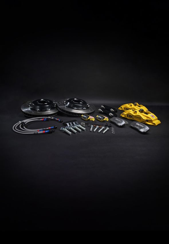
7.5. Exploded Diagram with Torque Specifications
60Nm (44 ft-lb)
Bleed Nipple
17Nm (12.5 ft-lb)
Banjo Bolt
20Nm (15 ft-lb)
100Nm (74 ft-lb)
7|PageBIG BRAKE KIT INSTALLATION
INSTRUCTIONS - Apollo-4 (100 Series)
7.6. Install Front Brake Pads.
* Insert the brake pads, position the pad spring clip, and then apply pressure to compress the spring using the
bolt collar till the M8 bolt can be re-inserted. Torque the M8 bolt to 13 Nm (10 ft-lb).
13Nm (10 ft-lb)
7.7. Install Front Brake Lines.
* Torque the banjo bolt to 25 Nm (18 ft-lb) [14mm hex socket] ensuring the line does not shift orientation.
Torque the hardline fitting to the torque specified in the vehicle manufacturer’s handbook.
Failure to use a copper washer on either side of the banjo fitting can result in a leak and loss of brake system
pressure under braking.
Front Axle install is now complete, now on to the Rear.
8. Installation of New Rear Components
8.1. Crack off rear wheel nuts.
8.2. Jack up the vehicle and place securely on axle stands.
8.3. Remove rear wheels.
8.4. Install rear brake lines.
8.5. Remove rear caliper from bracket.
8.6. Install new rear brake pads.
8.7. Re-fit rear brake caliper - Torque to manufacturers specifications
8|PageBIG BRAKE KIT INSTALLATION
INSTRUCTIONS - Apollo-4 (100 Series)
Front & Rear Installation complete, now to bleed the system.
9. Brake Bleeding Procedure
WARNING! Use caution to ensure that the Brake Fluid does not come in contact with any painted surfaces. If
Brake Fluid should contact these surfaces, wash them immediately with warm soapy water, or damage could
result.
9.1. If upgrading from regular DOT 4 or DOT 5.1 fluid to EBC BF307+, use a syringe to first remove as
much of the old brake fluid from the reservoir as possible.
9.2. Top the now empty reservoir up to ‘max’ with fresh/new BF307+ brake fluid. Check the reservoir
fluid level often throughout the bleed procedure to ensure it never runs dry.
9.3. Begin with 1 person in the driving seat and the second person at the caliper bleed nipple furthest
away from the master cylinder (usually a rear caliper).
9.4. Pump the pedal slowly and smoothly 3 times to fill the master cylinder, then on the third depress of
the pedal hold firm pressure.
9.5. The second person then opens the nipple, allowing the pressurised fluid to flow out into a container.
You may see some bubbles of air in the expelled fluid, good, as you must get all those air bubbles out
of the system. You may also see the fluid lighten in colour as the new fluid gets pulled through. As
soon as the pressurised fluid has stopped flowing close the nipple. The brake pedal must not be
released until the bleed nipple is closed otherwise air may get sucked back into the system.
9.6. Repeat steps 4-to-5 till no more air bubbles are visible in the expelled brake fluid.
9.7. Move to the second furthest caliper from the master cylinder, repeating the above process till the
caliper is bled of air. Keep repeating this process getting closer to the master cylinder each time, until
all calipers have been bled. (If the caliper to be bled has 2 bleed nipples, open the outer most bleed
nipple first and then bleed the inboard side of the caliper second).
9.8. Now go back to the furthest caliper from the master cylinder and re-bleed each caliper in sequence
to make sure no air remains in the brake system.
9.9. Once the system has been bled, re-tighten the bleed nipples to the manufacturer specified torque.
EBC calipers all have a bleed nipple tightening torque of 17Nm (13 ft-lb).
10. Leak Test Procedure
After the brakes have been bled, start the vehicles engine then firmly depress the brake pedal. Hold the
pressure for at least 30 seconds. Check the pedal is firm and does not sink under sustained pressure. Look
underneath the car and carefully inspect all hydraulic connections for any signs of leaks.
9|PageBIG BRAKE KIT INSTALLATION
INSTRUCTIONS - Apollo-4 (100 Series)
11. Main Bedding-In Procedure
The new brake calipers, discs and pads must all be bed-in properly to prevent damage and maximise
performance. DO NOT go racing or drive hard immediately after installing the new brake components
without following the bedding-in procedure detailed below.
Once 200 miles of gentle driving has been completed the pads should have deposited a dull grey transfer layer onto the
discs. The transfer layer is a thin layer of pad material on the disc surface which is critical to brake system performance.
Check the discs have an even dull grey appearance around the entire swept area, any splodges or un-evenness signifies the
pad has not yet fully bed into the disc which may lead to vibration due to ‘uneven friction deposits’ if the brake system is
pushed hard. In the event that the discs do not have an even dull grey appearance, continue to drive the vehicle gently until
an even transfer layer has been established. Now that the discs have an even dull grey appearance it’s time to thermally
condition the brake system by conducting the following bedding-in procedure on a quiet and safe stretch of road:
11.1. DRIVE 1 – Perform 15 medium pressure stops from 50 mph down to 20 mph (25-30% pedal effort
approx.)
COOL DOWN – After Drive 1 has been completed, drive the car at 50 mph for at least 5 miles with minimal
brake usage to allow the brakes to cool. Park the vehicle for at least 60 minutes or overnight to allow the
brakes to cool fully before Drive 2.
11.2. DRIVE 2 – Perform 20 higher intensity stops from 60 mph down to 10 mph (50% pedal effort, or half
the decel of an emergency stop)
COOL DOWN – After Drive 1 has been completed, drive the car at 50 mph for at least 5 miles with minimal
brake usage to allow the brakes to cool. Park the vehicle for at least 60 minutes or overnight to allow the
brakes to cool fully before Drive 3.
11.3. DRIVE 3 – Perform 15 hard stops from 60 mph down to 10 mph (75-80% pedal effort approx.). You
should smell the brakes and you may get some brake fade during this drive; this is known as ‘green
fade’ or ‘early life fade’ and Is perfectly normal and signifies any volatiles left over from manufacture
of the pads are being burnt off. Once you have pushed the pads through this green fade period the
pads will be conditioned for harder braking.
COOL DOWN – Drive the car at 50 mph for at least 8 miles with minimal brake usage to allow the brakes to cool fully before
coming to a halt.
NEVER COME TO A COMPLETE STOP WITH VERY HOT BRAKES. After a period of hard driving and whilst the
brakes are still hot it is critical not to come to a complete halt and leave your foot on the brake pedal. Doing so
will force the pads onto the disc, leading to hot spots whilst also causing excessive heat soak into the brake
caliper. After a spirited drive, always cool the brakes before coming to a halt. TIP: for automatic vehicles
coming to a stop with extremely hot brakes, put the vehicle into park and remove your foot from the brake
pedal so the brakes are disengaged.
NOTE: New brake calipers, or freshly resealed calipers can take up to 300 miles (480 km) to fully bed-in.
Immediately following the installation of new calipers the brake pedal may start off feeling slightly ‘long’,
however the brake pedal will continually improve throughout the caliper bed-in period as the seals settle into
their final position. If the brake pedal feels spongy after 300 miles, re-bleed the brakes.
DO NOT SKIP THIS STEP – After 1,000 miles lift the car, remove the wheels, and carefully inspect all brake
system components and connections for rub marks or damage. Pay particular attention to the brake line and
whether it shows any signs of rubbing or leaking.
THE ABOVE BED-IN PROCEDURE MUST ALSO BE REPEATED FOLLOWING THE
INSTALLATION OF: NEW SEALS, NEW PADS OR NEW DISCS.
10 | P a g eBIG BRAKE KIT INSTALLATION
INSTRUCTIONS - Apollo-4 (100 Series)
12. Additional Information
12.1. Brake Pad Replacement
PADS SHOULD ALWAYS BE REPLACED BEFORE THEY REACH THE LAST 2mm OF FRICTION MATERIAL. Never
wear pads down to the backing plate.
Always push the caliper pistons all the way back during a pad change. There should be at least 0.5mm gap
between the piston and pad following insertion of new pads, this gap is critical to enable some initial piston
movement to energise the fluid seals.
12.2. Disc Replacement
EBC Brakes Racing recommends replacing discs when the thickness becomes 2mm thinner overall (1mm on
each face) than when the disc was new. For example, if the new thickness of the disc is 28mm the minimum
thickness will be 26mm.
IMPORTANT *Discs must be regularly and frequently inspected for excessive heat crazing and cracking.
DANGER! **Discs with cracks arising from mounting holes / slots, inside diameter, or outside diameter should
be changed immediately.
DANGER! ***After heavy and prolonged use some surface crazing will often be evident. If this turns into
prominent surface cracks which are radiating towards the inside or outside diameter the disc MUST be
changed.
IMPORTANT: Always replace discs in axle sets, DO NOT only replace one disc.
12.3. Cleaning of Calipers
If the caliper uses an inner bore wiper seal, rather than a full dust boot type seal, ensure the sides of the piston
are clean by first cleaning with soapy water to remove the bulk of the dirt then wiping with isopropyl alcohol
before pushing the pistons all the way back.
CAUTION! *DO NOT USE ABRASIVES TO SCRUB THE PISTON OUTER DIAMETER.
12.4. Brake Fluid
EBC Brakes Racing supplies BF307+ high performance Super DOT 4 brake fluid with all Brake Kits, this fluid has
been specially formulated to provide outstanding performance for braking systems routinely operated at
extreme temperatures making this fluid ideal for fast street use, track days and racing. Do not mix BF307+
brake fluid with other brake fluids or its high performance may be compromised.
CAUTION! *NOT SUITABLE FOR USE WITH MINERAL OIL SYSTEMS. If in doubt consult vehicle handbook.
CAUTION! **Glycol fluid is highly corrosive and contact with paintwork by fingers contaminated with brake
fluids can cause severe paint damage. Ensuring that you do not touch paintwork and cleaning hands is
essential when working with glycol.
12.5. Assistance
EBC Brakes Racing has a dedicated technical support team to guide you in your pad selection, please contact
us and a member of our team will be happy to steer you towards the right material for your application:
kits@ebcbrakes.com
11 | P a g eYou can also read