2016-2020 Level Ultimate, TLM, & TL - SERVICE MANUAL - SRAM Service
←
→
Page content transcription
If your browser does not render page correctly, please read the page content below
2016-2020
Level Ultimate, TLM, & TL

SERVICE MANUAL

                            GEN.0000000006035 Rev B © 2019 SRAM, LLC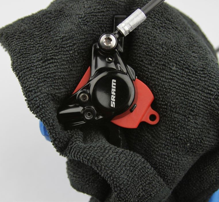
SRAM® LLC WARRANTY
EXTENT OF LIMITED WARRANTY
Except as otherwise set forth herein, SRAM warrants (i) Zipp® MOTO™ Rims to be free from defects in materials or workmanship for the lifetime of the
product, and (ii) its other products to be free from defects in materials or workmanship for a period of two years after original purchase. This warranty
only applies to the original owner and is not transferable. Claims under this warranty must be made through the retailer where the bicycle or the
SRAM component was purchased. Original proof of purchase is required. Except as described herein, SRAM makes no other warranties, guaranties,
or representations of any type (express or implied), and all warranties (including any implied warranties of reasonable care, merchantibility, or
fitness for a particular purpose) are hereby disclaimed.
LOCAL LAW
This warranty statement gives the customer specific legal rights. The customer may also have other rights which vary from state to state (USA), from
province to province (Canada), and from country to country elsewhere in the world.
To the extent that this warranty statement is inconsistent with the local law, this warranty shall be deemed modified to be consistent with such law,
under such local law, certain disclaimers and limitations of this warranty statement may apply to the customer. For example, some states in the United
States of America, as well as some governments outside of the United States (including provinces in Canada) may:
  a. Preclude the disclaimers and limitations of this warranty statement from limiting the statutory rights of the consumer
     (e.g. United Kingdom).
  b. Otherwise restrict the ability of a manufacturer to enforce such disclaimers or limitations.
FOR AUSTRALIAN CUSTOMERS:
This SRAM limited warranty is provided in Australia by SRAM LLC, 1000 W. Fulton Market, 4th Floor, Chicago, IL, 60607, USA. To make a warranty claim
please contact the retailer from whom you purchased this SRAM product. Alternatively, you may make a claim by contacting SRAM Australia, 6 Marco
Court, Rowville 3178, Australia. For valid claims SRAM will, at its option, either repair or replace your SRAM product. Any expenses incurred in making
the warranty claim are your responsibility. The benefits given by this warranty are additional to other rights and remedies that you may have under
laws relating to our products. Our goods come with guarantees that cannot be excluded under the Australian Consumer Law. You are entitled to a
replacement or refund for a major failure and for compensation for any other reasonably foreseeable loss or damage. You are also entitled to have
the goods repaired or replaced if the goods fail to be of acceptable quality and the failure does not amount to a major failure.

LIMITATIONS OF LIABILITY
To the extent allowed by local law, except for the obligations specifically set forth in this warranty statement, in no event shall SRAM or its third party
suppliers be liable for direct, indirect, special, incidental, or consequential damages.

LIMITATIONS OF WARRANTY
This warranty does not apply to products that have been incorrectly installed, adjusted, and/or maintained according to the respective SRAM user
manual. The SRAM user manuals can be found online at sram.com, quarq.com, or zipp.com.
This warranty does not apply to damage to the product caused by a crash, impact, abuse of the product, non-compliance with manufacturers
specifications of usage or any other circumstances in which the product has been subjected to forces or loads beyond its design.
This warranty does not apply when the product has been modified, including, but not limited to any attempt to open or repair any electronic and
electronic related components, including the motor, controller, battery packs, wiring harnesses, switches, and chargers.
This warranty does not apply when the serial number or production code has been deliberately altered, defaced or removed.
This warranty does not apply to damage to Zipp MOTO Rims outside of intended use (Trail/Enduro) situations or incurred in connection with Downhill/
Dual Crown biycles.
All Zipp MOTO Rim warranty claims will be evaluated by a SRAM/Zipp Authorized Service Location.
This warranty does not apply to normal wear and tear. Wear and tear parts are subject to damage as a result of normal use, failure to service
according to SRAM recommendations and/or riding or installation in conditions or applications other than recommended.
WEAR AND TEAR PARTS ARE IDENTIFIED AS:
• Dust seals                           • Stripped threads/bolts (aluminium,   • Handlebar grips                       • Transmission gears
• Bushings                               titanium, magnesium or steel)        • Shifter grips                         • Spokes
• Air sealing o-rings                  • Brake sleeves                        • Jockey wheels                         • Free hubs
• Glide rings                          • Brake pads                           • Disc brake rotors                     • Aero bar pads
• Rubber moving parts                  • Chains                               • Wheel braking surfaces                • Corrosion
• Foam rings                           • Sprockets                            • Bottomout pads                        • Tools
• Rear shock mounting                  • Cassettes                            • Bearings                              • Motors
  hardware and main seals              • Shifter and brake cables             • Bearing races                         • Batteries
• Upper tubes (stanchions)               (inner and outer)                    • Pawls                                 • Driver Bodies

Notwithstanding anything else set forth herein, the battery pack and charger warranty does not include damage from power surges, use of improper
charger, improper maintenance, or such other misuse.
This warranty shall not cover damages caused by the use of parts of different manufacturers.
This warranty shall not cover damages caused by the use of parts that are not compatible, suitable and/or authorised by SRAM for use with SRAM
components.
This warranty shall not cover damages resulting from commercial (rental) use.

                                                                                                                                                             2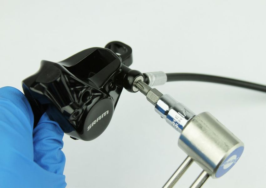
SAFETY FIRST!
We care about YOU. Please, always wear your safety glasses and
       protective gloves when servicing SRAM products.
            Protect yourself! Wear your safety gear!

                                                                    3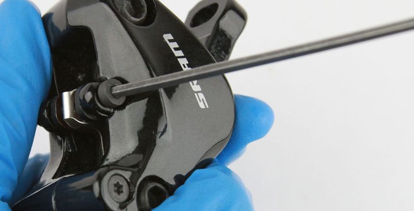
TABLE OF CONTENTS
SRAM LEVEL BRAKE SYSTEMS SERVICE........................................................................................................................................................5
       SERVICE PROCEDURES..................................................................................................................................................................................................................................6

TROUBLESHOOTING...........................................................................................................................................................................................7
       DISC BRAKE PAD ADVANCEMENT PROCEDURE.................................................................................................................................................................................. 7
       DISC BRAKE PAD GAP RESET - MONOBLOCK CALIPER ONLY......................................................................................................................................................... 7
       DISC BRAKE PAD RETRACTION RESET - MONOBLOCK CALIPER ONLY.......................................................................................................................................8

SRAM LEVEL ULTIMATE & TLM CALIPER SERVICE........................................................................................................................................9
       PARTS AND TOOLS NEEDED FOR SERVICE...........................................................................................................................................................................................9
       LEVEL CALIPER EXPLODED VIEW - 2 PIECE CALIPER.........................................................................................................................................................................9
       LEVEL CALIPER EXPLODED VIEW - MONOBLOCK CALIPER........................................................................................................................................................... 10
       CALIPER BRAKE PAD REMOVAL................................................................................................................................................................................................................. 11
       CALIPER PISTON REMOVAL........................................................................................................................................................................................................................ 12
       CALIPER PISTON INSTALLATION.............................................................................................................................................................................................................. 18

SRAM LEVEL TL CALIPER SERVICE............................................................................................................................................................... 22
       PARTS AND TOOLS NEEDED FOR SERVICE........................................................................................................................................................................................ 22
       SRAM LEVEL TL CALIPER EXPLODED VIEW........................................................................................................................................................................................ 22
       CALIPER BRAKE PAD REMOVAL............................................................................................................................................................................................................... 23
       CALIPER PISTON REMOVAL....................................................................................................................................................................................................................... 24
       CALIPER PISTON INSTALLATION............................................................................................................................................................................................................. 27

LEVER SERVICE................................................................................................................................................................................................. 30
       PARTS AND TOOLS NEEDED FOR SERVICE........................................................................................................................................................................................ 30
       LEVEL ULTIMATE LEVER EXPLODED VIEW.......................................................................................................................................................................................... 30
       LEVEL TLM & TL LEVER EXPLODED VIEW............................................................................................................................................................................................. 31
       LEVER BLADE REMOVAL............................................................................................................................................................................................................................ 32
       PISTON ASSEMBLY REMOVAL.................................................................................................................................................................................................................. 36
       PISTON ASSEMBLY INSTALLATION..........................................................................................................................................................................................................37
       LEVER BLADE INSTALLATION................................................................................................................................................................................................................... 38

DISC BRAKE PAD AND ROTOR BED-IN PROCEDURE................................................................................................................................ 43

LEVEL ULTIMATE LEVER BEARING REPLACEMENT................................................................................................................................... 44

                                                                                                                                                                                                                  Table of Contents                      4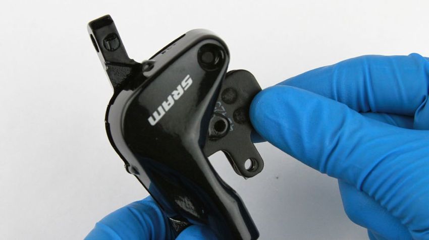
SRAM Level Brake Systems Service
We recommend that you have your SRAM Level components serviced by a qualified bicycle mechanic. Servicing SRAM components requires
knowledge of bicycle mechanics as well as the special tools and lubricants/fluids used for service.
SRAM brake systems need to be serviced periodically to optimize braking function. If brake fluid is leaking from any area of the brake there may be
damage or wear and tear to the internal moving parts. If the system has been contaminated with the wrong fluid there may be damage to all rubber
and plastic internal parts. If your brake was damaged in a crash there may be damage to the lever blade, pushrod, and housing assemblies. Inspect
and replace these parts to restore proper brake function.
Visit www.sram.com/service for the latest SRAM Spare Parts catalog and technical information. For order information, please contact your local SRAM
distributor or dealer.
      For recycling and environmental compliance information, please visit www.sram.com/company/environment.
Information contained in this publication is subject to change at any time without prior notice. Your product's appearance may differ from the pictures
contained in this publication.

                                                         SAFETY INSTRUCTIONS
 Do not use mineral oil or DOT 5 fluid.
 If the brake system has been contaminated with mineral oil or DOT 5 fluid, flush all of the parts with soapy water, rinse them with clean water, then
 allow all the parts to dry prior to rebuilding. Install new seals, a new bladder, and replace the hose.
 For best results, use only SRAM High-Performance DOT 5.1 brake fluid. If SRAM brake fluid is not available, only use DOT 5.1 or 4 brake fluid.
 Use only DOT compatible grease.
 Always wear safety glasses and nitrile gloves when working with DOT brake fluid.
 Used DOT brake fluid should be recycled or disposed of in accordance to local and federal regulations.
 Never pour DOT brake fluid down a sewage or drainage system or into the ground or a body of water.
 Do not allow any brake fluid to come in contact with the brake pads. If this occurs, the pads are contaminated and must be replaced.
 Place an oil pan on the floor underneath the area where you will be working on the brake.
 Servicing your brakes removes all of the brake fluid from the system. You must bleed your brakes after you service the brake system. Consult the
 SRAM MTB Disc Brake Hose Shortening and Bleed Manual at www.sram.com/service.

                                                                   ⚠ CAUTION
 Do not use mineral oil or DOT 5 fluid. Do not use tools, rags, or syringes that are contaminated with mineral oil or DOT 5 fluid. Using contaminated
 materials will result in permanent damage to the seals and reduce braking performance. Brakes must be replaced if contaiminated with mineral oil
 or DOT 5 fluid.

                                                                                                             SRAM Level Brake Systems Service             5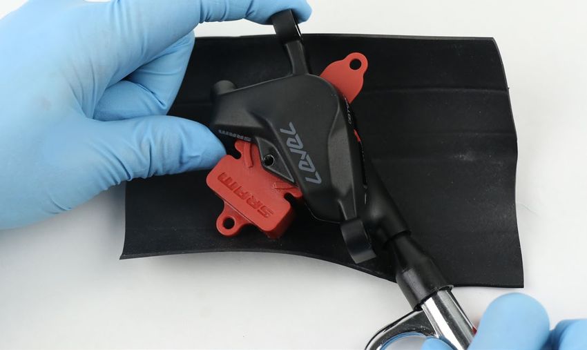
Service Procedures
The following procedures should be performed throughout service, unless otherwise specified.

Clean the part with isopropyl alcohol and a clean, lint-free rag.
Clean the sealing surface on the part and inspect it for scratches.

Replace the o-ring or seal with a new one from the service kit.
Use your fingers, a ziptie, or a pick to pierce and remove the old seal or o-ring.
Apply DOT grease to the new seal or o-ring when instructed.

                                  NOTICE
 Do not scratch any sealing surfaces when servicing the product. Scratches
 can cause leaks. Consult the spare parts catalog to replace the damaged
 part.

Use aluminum soft jaws when placing a part in a bench vise.                                    Specified torque value in N·m (in-lb)
Tighten the part with a torque wrench to the torque value listed in the red bar.
When using a crowfoot socket and torque wrench, install the crowfoot socket
at 90 degrees to the torque wrench.

                                                                                                       Service Procedures              6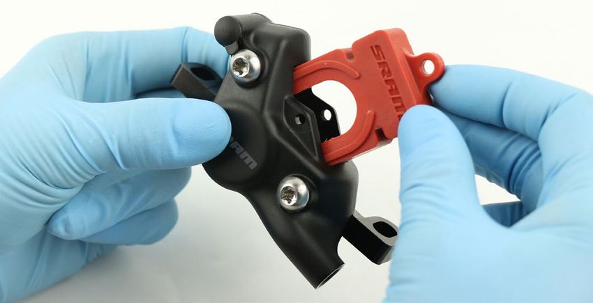
Tr o u b l e s h o o t i n g
 Disc Brake Pad Advancement Procedure
If your brakes exhibit excessive lever throw or spongy feel, perform the following steps before bleeding the system:
      Clamp the bicycle into a bicycle work stand.
 1
      Remove the wheel from the affected caliper.
 2
      Remove the brake pads.
 3
      Install the pad spacer.
 4
      Squeeze the brake lever several times until both pistons have advanced and contact the pad spacer. One piston may move faster than the
 5    other; continue to squeeze the lever until the second piston touches the spacer.

      Remove the pad spacer.
 6
      Use a plastic tire lever to push the pistons back into the caliper bores.
 7
      Repeat steps 4-7 until both pistons are move freely.
 8
      Install the brake pads and the wheel.
 9
      Loosen the caliper bolts.
10
      Lightly squeeze (approx. 4 lbs) the brake lever several times to position the brake pads to the proper distance from the rotor.
 11
      Center the caliper on the rotor, and tighten the caliper bolts.
12
      Spin the wheel and check the brake function. The pistons should move freely and there should not be excessive brake lever throw. If there is no
13    improvement in the brake function, proceed to the service manual for your caliper.

 Disc Brake Pad Gap Reset - Monoblock caliper only
If the brake lever was squeezed without a pad spacer or rotor installed in the caliper, the pad gap may have been reduced. If this happens the rotor
might not have enough clearance in the caliper without rubbing. Perform this procedure to reset the pad gap:
      Remove the wheel from the affected caliper.
  1
      Install the 2.8 mm side of a Monoblock pad spacer between the brake
 2    pads.
      Squeeze the brake lever hard 5 times (approximately 22 lbs).
 3
      Remove the spacer from the caliper, and install the 2.4 mm side of the
4     SRAM spacer between the brake pads.
      Squeeze the brake lever lightly 5 times (approximately 4 lbs or less).
5
      Remove the pad spacer.
6                                                                                      2.4 mm side          Monoblock pad spacer           2.8 mm side

      Re-install the wheel, and re-center the caliper.
 7

                                                                                                                                   Troubleshooting       7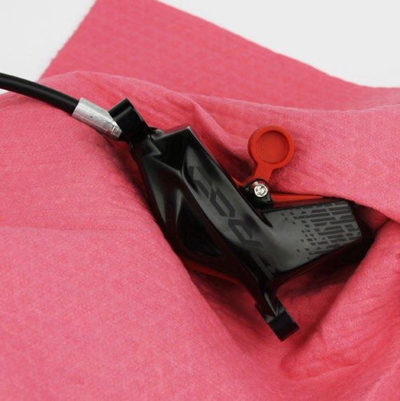
Disc Brake Pad Retraction Reset - Monoblock caliper only
If there is still insufficient clearance between the brake pads and rotor after performing the pad gap reset procedure, perform this overnight procedure
to reset the retraction distance between the caliper pistons:
      Remove the wheel from the affected caliper.
  1
      Install the 2.8 mm side of a Monoblock pad spacer between the brake
 2    pads and remove it without squeezing the brake lever.
      Install the 2.4 mm side of the Monoblock pad spacer between the
3     brake pads.
      Squeeze the brake lever lightly 5 times (approximately 4 lbs or less).
4
      Allow the system to sit, untouched, for 12-24 hours.
5
      Remove the pad spacer.
6                                                                                      2.4 mm side         Monoblock pad spacer           2.8 mm side

      Re-install the wheel, and re-center the caliper.
 7

                                                                                      Disc Brake Pad Retraction Reset - Monoblock caliper only          8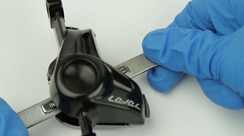
SRAM Level Ultimate & TLM Caliper Service

P a r t s a n d To o l s N e e d e d f o r S e r v i c e

Parts                                                                          Common Tools
• Caliper Piston Kit - Level Ultimate/TLM Monoblock (Monoblock                 • 2.5 & 5 mm hex wrench
  calipers)
                                                                               • T25 TORX wrenchs
• Caliper Piston Kit - Level Ultimate/TLM Phen. B1 (2 piece calipers)
                                                                               • T25 TORX bit socket
Safety and Protection Supplies
                                                                               • Digital caliper
• Apron
                                                                               • Needle nose pliers
• Clean, lint-free shop towels
                                                                               • Pick with a 90 degree bent tip
• Nitrile gloves
                                                                               • Air compressor with rubber-tipped air chuck nozzle
• Oil pan
                                                                               • Soft rubber or piece of inner tube
• Safety glasses
                                                                               • Torque wrench
Lubricants and Fluids
                                                                               SRAM Tools
• Isopropyl alcohol
                                                                               • SRAM Brake Bleed Kit (includes: Bleed Block and Bleeding
• SRAM High-Performance DOT 5.1 brake fluid. If SRAM brake fluid is not          Edge Fitting)
  available, only use DOT 5.1 or 4 brake fluid.
                                                                               • HRD Bleed Block (2 piece calipers)
• SRAM DOT assembly grease
                                                                               • Monoblock Bleed Block (Monoblock calipers)
                                                                               • Monoblock caliper 21 mm piston removal tool
                                                                               • Level/AXS Caliper Piston Removal Tool
                                                                               • Level pad spreader tool
                                                                               • Level piston plug

Level Caliper Exploded View - 2 piece caliper

                                                                                                                                 Hose
          Pad retention bolt
                      H-Spring
                                 Brake pads                                                                                      Hose Boot
                                                                        Caliper body
                                        Caliper piston                  seal

                                                      Piston seal                                                                Compression Nut

                                                                                       Caliper half                              Compression Fitting

                                                                                                                      Cross-body
                                                                                                                      bolt

                                                Caliper
                                                body seal                                                                   Piston seal

                                                                                                                                      Caliper piston
                                                                              Caliper half
                                                                                                                                                E-clip
                                                                                                       Cross-body
                                                                                                       bolt

                                                                                                      SRAM Level Ultimate & TLM Caliper Service          9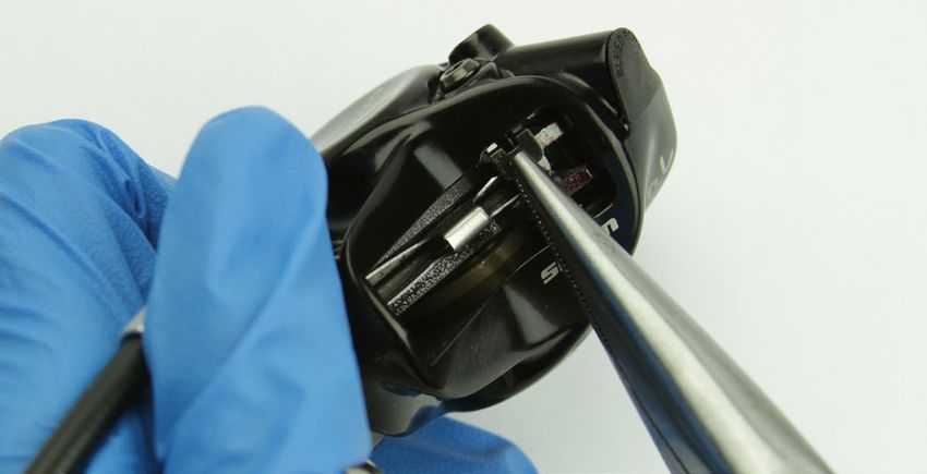
Level Caliper Exploded View - Monoblock caliper

                            Piston seal

                                                     Brake pads
  E-clip                                                                                                  Hose
                                                                         Caliper
                                                                                           Banjo

           Caliper piston                                                                                         Banjo
                                                                                                                  bolt
                                                                                                       Banjo
                                                                                                       o-ring

                                                                                                   Piston seal

                                          H-spring
                                                                                                                 Caliper piston

                                                            Bleed port

                                                     Bleed port plug
                                                                                              Pad retention bolt

                                                                            Level Caliper Exploded View - Monoblock caliper       10
Caliper Brake Pad Removal
Remove the caliper from the frame, then remove the mounting bracket
1 and the hardware from the caliper. Set them aside in the order that they
were removed.
Remove the E-clip from the pad retention bolt, then remove the pad
2 retention bolt from the caliper.
Needle nose pliers Monoblock caliper
Needle nose pliers 2 piece caliper
2.5 mm Monoblock caliper
2.5 mm 2 piece caliper
Remove the brake pads from the caliper.
3 Monoblock Caliper
NOTICE
Brake pads must be replaced if the total thickness of the backing
plate and pad friction material is less than 3 mm.
2 piece caliper
Digital caliper
Caliper Brake Pad Removal 11Caliper Piston Removal
NOTICE
DOT brake fluid will damage painted surfaces. If any fluid comes in contact with a painted surface (i.e. your frame) or printing on the brakes, wipe
it off immediately and clean it with isopropyl alcohol or water. Damage to painted and/or printed surfaces by DOT brake fluid is not covered under
warranty.
2 Piece caliper: Remove the compression nut and hose.
1 T25 Monoblock caliper
Monoblock caliper: Remove the banjo bolt and hose.
NOTICE
Fluid will drip. Place an oil pan and/or shop towel under the hose.
8 mm flare wrench 2 piece caliper
2 piece calipers: Insert the Level / AXS Caliper Piston Removal Tool.
2
Piston removal tool 2 piece caliper
Monoblock caliper: Insert the SRAM Monoblock caliper 21 mm piston 2.5 mm Monoblock caliper
removal tool, then install the pad retention bolt into the caliper.
⚠ CAUTION
Monoblock caliper: The pad retention bolt must be installed. If the
pad retention bolt is not installed the SRAM piston removal tool may
dislodge rapidly from the caliper, which can lead to bodily injury or
damage to the parts.
Piston removal tool Monoblock caliper
Caliper Piston Removal 12Firmly press a rubber-tipped air chuck nozzle into the banjo port. Hold
3 the caliper securely against a rubber surface and force air into the
banjo port to dislodge the piston from the caliper.
⚠ CAUTION - EYE HAZARD
Wear safety glasses.
The caliper piston may dislodge rapidly from the caliper, which can
lead to bodily injury or damage to the parts. Point the caliper piston
toward a rubber surface to prevent the piston from becoming a
projectile.
Rubber-tipped air chuck nozzle 2 piece caliper
Rubber-tipped air chuck nozzle Monoblock caliper
Monoblock caliper: Remove the pad retainer bolt.
4
2.5 mm Monoblock caliper
Remove the piston and the piston removal tool from the caliper.
5 Piston removal tool Monoblock caliper
Piston removal tool 2 piece caliper
Piston removal tool Monoblock caliper
Piston removal tool 2 piece caliper
Caliper Piston Removal 13Insert the Level piston plug so that it fits snugly into the empty piston
6 bore and is flush with the inside of the caliper.
Piston plug Monoblock caliper
Piston plug 2 piece caliper
Insert the Level / AXS Caliper Piston Removal Tool (2 piece caliper) or
7 the Monoblock Caliper 21 mm Piston Removal Tool (Monoblock caliper)
so that it will capture the still-installed piston. Make sure the horse-shoe
opening is aligned with the tab on the piston plug.
Piston removal tool 2 piece caliper
Monoblock caliper: Use a 2.5 mm hex wrench to install the pad 2.5 mm Monoblock caliper
retention bolt in order to hold the piston removal tool in place.
⚠ CAUTION
The pad retention bolt must be installed. If the pad retention bolt is
not installed the SRAM piston removal tool may dislodge rapidly from
the caliper, which can lead to bodily injury or damage to the parts.
Piston plug 2 piece caliper
Caliper Piston Removal 14Firmly press a rubber-tipped air chuck nozzle into the banjo port. Hold
8 the caliper securely against a rubber surface and force air into the
banjo port to dislodge the piston from the caliper.
⚠ CAUTION - EYE HAZARD
Wear safety glasses. The caliper piston may dislodge rapidly from the
caliper, which can lead to bodily injury or damage to the parts. Point
the caliper piston toward a rubber surface to prevent the piston from
becoming a projectile.
Rubber-tipped air chuck nozzle 2 piece caliper
Rubber-tipped air chuck nozzle Monoblock caliper
Monoblock caliper: Remove the retention bolt.
9
2.5 mm Monoblock caliper
Caliper Piston Removal 15Remove the piston removal tool, the piston, and the piston plug from
10 the caliper.
Piston removal tool Monoblock caliper
Piston removal tool 2 piece caliper
Piston removal tool Monoblock caliper
Piston removal tool 2 piece caliper
Piston plug Monoblock caliper
Piston plug 2 piece caliper
2 piece caliper: Remove the cross-body bolts from the caliper.
11
Remove the body seals from the caliper body.
T25 2 piece caliper
Caliper Piston Removal 16Use a pick to remove the piston seals from each piston bore.
12 Pick Monoblock caliper
⚠ CAUTION
Do not scratch the seal gland with the pick. Scratches could cause
fluid to leak when the brake is applied, which will contaminate the
brake pads and could lead to a brake failure.
Pick 2 piece caliper
Spray isopropyl alcohol inside each piston bore, the inside and the
13 outside of the caliper, and all of the removed parts and clean them with
Monoblock caliper
a shop towel.
NOTICE
If the system has been contaminated with mineral oil or DOT 5 fluid,
flush all of the parts with soapy water, rinse them with clean water,
then allow all of the parts to dry prior to rebuilding. Install all new
seals and a new brake hose.
For the best braking performance, use only SRAM DOT 5.1 brake fluid.
If SRAM fluid is not available, use only DOT 5.1 or 4 brake fluid.
2 piece caliper
Caliper Piston Removal 17Caliper Piston Installation
NOTICE
DOT brake fluid will damage painted surfaces. If any fluid comes in contact with a painted surface (i.e. your frame) or printing on the brakes, wipe
it off immediately and clean it with isopropyl alcohol or water. Damage to painted and/or printed surfaces by DOT brake fluid is not covered under
warranty.
Apply a small amount of SRAM 5.1 DOT brake fluid to new piston seals
1 and install the piston seals into each piston bore.
Monoblock caliper
2 piece caliper
Inspect the caliper pistons for damage and replace the pistons if
2 necessary.
Use your gloved finger to apply a small amount of SRAM DOT 5.1 brake
fluid to each piston, then install each piston into each piston bore.
NOTICE
For the best braking performance, use only SRAM DOT 5.1 brake
fluid. If SRAM brake fluid is not available, use only DOT 5.1 or 4
brake fluid. Do not use grease. Grease will prevent the pistons
from fully retracting into the caliper bores which will reduce braking
performance.
SRAM DOT 5.1 brake fluid
Monoblock caliper
2 piece caliper
Tip: If a piston is difficult to install into a piston bore, lay the caliper on
a flat surface. Slide a thin wrench through the caliper, then gently and
evenly press the piston into the bore.
Caliper Piston Installation 182 piece caliper: Install new body seals into the caliper body.
3 T25 11 N·m (97 in-lb)
Install the cross-body bolts into the caliper body, then tighten.
2 piece caliper
2 piece caliper: Install the hose boot onto the new hose. Apply DOT
4 grease to the hose barb threads. Thread the hose barb into the hose
until it is flush with the end of the hose.
NOTICE
Do not overtighten the hose barb. Overtightening may cause damage
to the hose liner.
2 piece caliper
T8
T8 DOT grease 2 piece
2 piece caliper: Install the compression nut onto the hose.
2 piece caliper
Caliper Piston Installation 192 piece caliper: Thread the compression fitting over the hose barb, DOT grease 2 piece caliper
counter-clockwise, until it is flush or slightly lower than the hose barb.
The compression fitting is reverse threaded.
Apply DOT grease to the outside of the compression fitting and the
threads of the compression nut.
2 piece caliper
2 piece caliper: Install the hose into the caliper while threading the 2 piece caliper
compression nut into the caliper by hand. Tighten the compression nut.
Install the hose boot over the compression nut.
8 mm 5 N·m (44 in-lb) 2 piece
Monoblock caliper: Remove the o-ring from the banjo bolt. DOT grease
Install the new o-rings and apply a thin layer of grease. Install the banjo
bolt into the banjo boot.
Monoblock caliper: Tighten the banjo bolt with the banjo boot at the
desired angle.
T25 5 N·m (44 in-lb) Monoblock caliper
Caliper Piston Installation 202 piece caliper: Install the HRD bleed block into the caliper.
5
HRD bleed block 2 piece caliper
Monoblock caliper: Insert the Monoblock bleed block into the caliper, 2.5 mm
then install the pad retention bolt.
Monoblock bleed block 20 mm or 15 mm Thru Axle
⚠ CAUTION
You must bleed your brakes before reinstalling the brake pads. Installing the brake pads prior to bleeding the brakes could contaminate the brake
pads and could lead to brake failure.
Spray isopropyl alcohol on the caliper and clean it with a shop towel.
6 Monoblock caliper
2 piece caliper
Visually check your work. If any of the o-rings protrude from the banjo fitting or banjo bolt, remove and replace the o-ring, then repeat the installation
process.
⚠ CAUTION
Servicing your brakes removes all of the fluid from the system. You must bleed the brakes after you service the brake caliper and/or lever. For brake
bleed, brake hose shortening, and brake pad replacement instructions, visit www.sram.com/service.
Caliper Piston Installation 21SRAM Level TL Caliper Service
P a r t s a n d To o l s N e e d e d f o r S e r v i c e
Parts Common Tools
• Caliper Piston Kit - Level TL/T • 2.5 mm and 5 mm hex wrenches
Safety and Protection Supplies • 5 mm hex bit socket
• Safety glasses • 8 mm flare nut wrench
• Nitrile gloves • 8 mm open end wrench and crowfoot
• Oil pan • Needle nose pliers
• Clean, lint-free shop towel • Digital caliper
Lubricants and Fluids • Pick with a 90 degree bent tip
• Isopropyl alcohol • Torque wrench
• SRAM DOT 5.1 brake fluid • Air compressor with a rubber-tipped chuck nozzle
If SRAM fluid is not available, only use DOT 5.1 or 4 fluid
• Soft rubber or piece of inner tube
SRAM Tools
• SRAM Brake Bleed Kit (includes: Bleed Block and Bleeding Edge
Fitting)
SRAM Level TL Caliper Exploded View
Crimped hose fitting
Caliper body bolt
Bleed screw
Caliper o-ring
H-spring Piston seal
Caliper hose
Caliper
port
piston
Pad pin
Piston seal
Caliper piston Brake pad E-clip
Outboard caliper body Inboard caliper body
SRAM Level TL Caliper Service 22Caliper Brake Pad Removal
Remove the brake caliper from the fork or frame.
1
Remove the caliper mounting bracket and hardware from the caliper
then set the bracket and hardware aside in the order they were
removed.
Use needle nose pliers to remove the E-clip from the pad pin.
2 2.5 mm hex wrench
Use a 2.5 mm hex wrench to remove the pad pin from the caliper.
Needle nose pliers 20 mm or 15 mm Thru Axle
3 Pull the brake pads out of the caliper.
NOTICE
Brake pads must be replaced if the total thickness of the backing
plate and pad friction material is less than 3 mm.
Digital caliper
Caliper Brake Pad Removal 23Caliper Piston Removal
NOTICE
DOT brake fluid will damage painted surfaces. If any fluid comes in contact with a painted surface (i.e. your frame) or printing on the brakes, wipe
it off immediately and clean it with isopropyl alcohol or water. Damage to painted and/or printed surfaces by DOT brake fluid is not covered under
warranty.
Use an 8 mm flare nut wrench to remove the crimped hose fitting.
1
Pull the brake hose and crimped hose fitting from the caliper hose port.
Brake fluid will leak, so hold the caliper over a container to catch the
fluid.
8 mm flare nut wrench
Use a 5 mm hex wrench to remove the caliper body bolts.
2
5 mm hex wrench
Separate the caliper body halves.
3
Use a T10 TORX wrench to remove the bleed screw.
4
T10 TORX wrench
Caliper Piston Removal 24Place the inboard caliper half, piston side down, on a soft rubber mat or
5 a small section of inner tube on a flat surface.
Insert a rubber-tipped air chuck nozzle into the caliper hose port.
⚠ CAUTION - EYE HAZARD
Wear safety glasses.
The caliper piston may dislodge rapidly from the caliper, which can
lead to bodily injury or damage to the parts. Point the caliper piston
toward a rubber surface before forcing air into the caliper.
Rubber Rubber-tipped air chuck nozzle 22 m
While firmly pushing against the caliper half and chuck nozzle, squeeze
the air chuck to force air into the caliper hose port and dislodge the
piston from the caliper.
Continue to force air into the caliper until the piston is dislodged.
Remove the piston from the caliper.
Place the outboard caliper body half, piston side down, on a soft rubber
6 mat or a small section of inner tube on a flat surface.
Insert a rubber-tipped air chuck nozzle into the bleed screw opening.
⚠ CAUTION - EYE HAZARD
Wear safety glasses.
The caliper piston may dislodge rapidly from the caliper, which can
lead to bodily injury or damage to the parts. Point the caliper piston
toward a rubber surface before forcing air into the caliper.
Rubber Rubber-tipped air chuck nozzle 22 m
While firmly pushing against the caliper half and chuck nozzle, squeeze
the air chuck to force air into the bleed screw opening and dislodge
the piston from the caliper.
Continue to force air into the caliper until the piston is dislodged.
Remove the piston from the caliper.
Use a T10 TORX wrench to remove the bleed screw. 25Use a pick to remove the piston seal from inside both the inboard and
7 outboard half of the caliper body.
Spray isopropyl alcohol into the caliper piston bores, and clean them
with a shop towel, then install a new seal inside each caliper body half.
NOTICE
Do not scratch the seal gland with a pick. It could result in a slow fluid
leak when the brake is applied.
Use a T10 TORX wrench to remove the bleed screw. 26Caliper Piston Installation
NOTICE
DOT brake fluid will damage painted surfaces. If any fluid comes in contact with a painted surface (i.e. your frame) or printing on the brakes, wipe
it off immediately and clean it with isopropyl alcohol or water. Damage to painted and/or printed surfaces by DOT brake fluid is not covered under
warranty.
Inspect the caliper pistons for damage and replace the pistons if
1 necessary.
SRAM DOT 5.1 brake fluid
Use your gloved finger to apply a small amount of SRAM DOT 5.1 brake
fluid to each piston, then install each piston into each piston bore.
NOTICE
For the best braking performance, use only SRAM DOT 5.1 brake fluid.
If SRAM fluid is not available, use only DOT 5.1 or 4 brake fluid. Do not
use grease. Grease will prevent the pistons from fully retracting into
the caliper bores, which will reduce braking performance.
Spray isopropyl alcohol on the caliper halves and both of your gloves,
2 and clean them with a shop towel.
Use a pick to remove the caliper o-ring from the inboard caliper half
3 and install a new o-ring.
Caliper Piston Installation 27Use a pick to remove the o-ring from the crimped hose fitting.
4
Apply a small amount of DOT 5.1 fluid to the new o-ring and
install it.
Align the caliper body halves together, then thread the caliper body
5 bolts into the caliper by hand.
Use a torque wrench with a 5 mm hex bit socket to tighten each bolt to
6 11 N·m (97 in-lb).
5 mm hex 11 N·m (97 in-lb) T25 TO
Use a T10 TORX wrench to install the bleed screw.
7
T10 TORX wrench
Caliper Piston Installation 28Use a torque wrench with an 8 mm flare nut crowfoot socket to tighten
8 the crimped hose fitting into the caliper hose port to
11 N.m (97 in-lb).
8 mm flare nut crowfoot socket 11 Nm (97 in-lb) T25 TO
Insert the bleed block into the caliper.
9
⚠ CAUTION
You must bleed your brakes before reinstalling the brake pads.
Installing the brake pads prior to bleeding the brakes could
contaminate the brake pads and could lead to a brake failure.
Bleed block
Spray isopropyl alcohol on the caliper and clean it with a shop towel.
10
Visually check your work. If an o-ring protrudes from the crimped hose fitting, remove and replace the o-ring, then repeat the installation process.
⚠ CAUTION
Overhauling the caliper removes all of the fluid from the caliper. You must bleed the brakes for optimal performance. For brake bleed, brake hose
shortening, and brake pad replacement instructions, visit www.sram.com/service.
Caliper Piston Installation 29Lever Service
P a r t s a n d To o l s N e e d e d f o r S e r v i c e
Parts Common Tools
• Lever Internals Kit - Level Ultimate/TLM/TL • T8, T10, & T25 TORX wrench
Safety and Protection Supplies • T10 TORX bit socket
• Safety glasses • 8 mm flare nut wrench
• Nitrile gloves • 8 mm open end wrench and crowfoot
• Oil pan • Long-tipped snap ring pliers
• Clean, lint-free shop towel • Pick with a 90 degree bent tip
Lubricants and Fluids • Rubber mallet
• Isopropyl alcohol • Torque wrench
• SRAM DOT 5.1 brake fluid SRAM Tools
If SRAM fluid is not available, only use DOT 5.1 or 4 fluid
• SRAM Brake Bleed Kit (includes: Bleed Block and Bleeding Edge
Fitting)
• SRAM lever pivot tool
• SRAM hydraulic hose cutter
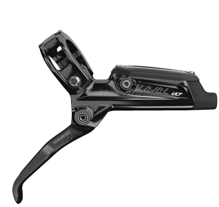
Level Ultimate Lever Exploded View
Reservoir bolts (2)
Reservoir cap
Hose boot
Bladder
Hose
Hose barb
Piston assembly
Compression nut SwingLink
push rod
Washer
Compression fitting Reach
adjuster
Bleed port screws (2)
Lever body
Lever pivot bolts (2) Snap ring
Piston assembly
(Stealth-a-majig- OEM)
Lever blade
Lever Service 30Level TLM & TL Lever Exploded View
Reservoir bolts (2)
Hose boot Reservoir cap
Hose
Bladder Lever blade bushings (2)
Hose barb
Compression nut Piston assembly
Compression fitting
Washer SwingLink
Spring push rod
Bleed port screws (2) bushing
Lever body
Piston assembly Snap ring
(Stealth-a-majig- OEM)
Pivot pin
Inboard spring
Lever blade
Level TLM & TL Lever Exploded View 31Lever Blade Removal
NOTICE
DOT brake fluid will damage painted surfaces. If any fluid comes in contact with a painted surface (i.e. your frame) or printing on the brakes, wipe
it off immediately and clean it with isopropyl alcohol or water. Damage to painted and/or printed surfaces by DOT brake fluid is not covered under
warranty.
Use a T25 TORX wrench or a 4 mm hex wrench to remove the brake
1 clamp bolt from the discrete clamp, MMX, or XLoc (XLoc requires
removal of the shifter) and remove the brake lever from the handlebar.
Pull the hose boot away from the brake body to expose the
2 compression nut, then slide the boot down the brake hose.
Use an 8 mm flare nut wrench to unthread the hose compression nut,
3 then pull the brake hose and compression fitting from the brake lever
body.
8 mm flare nut wrench
Use a T10 TORX wrench to remove the reservoir cap bolts from the
4 reservoir cap.
T10 TORX wrench
Lever Blade Removal 32Remove the reservoir cover and bladder from the lever body.
5
Pour the remaining brake fluid into an oil pan. Squeeze the lever blade
6 to force any remaining brake fluid out of the lever body.
NOTICE
If the system has been contaminated with mineral oil or DOT 5 fluid,
flush all of the parts with soapy water, rinse with clean water, then
allow all of the parts to dry prior to rebuilding.
Install all new seals and a new brake hose.
For the best braking performance, use only SRAM DOT 5.1 brake fluid.
If SRAM fluid is not available, use only DOT 5.1 or 4 brake fluid.
Separate the bladder from the reservoir cover.
7
Spray isopropyl alcohol on the bladder and the reservoir cover, then
clean them with a shop towel.
NOTICE
All components must be completely dry before reinstalling them.
Moisture residue from cleaning the bladder can leak out of the
bladder as it dries, which can be misinterpreted as a system leak,
when it is not.
Lever Blade Removal 33Ultimate: Use a T10 TORX wrench to remove each lever pivot bolt.
8
T10 TORX wrench
TLM/TL: Use a 2 mm hex wrench to rotate the reach adjust counter-
clockwise and set the reach adjust position to the minimum setting.
2 mm hex wrench
TLM/TL: Place the lever body on the edge of a table, allowing the
pivot pin to hang off of the side of the table, then insert the SRAM
aftermarket lever pivot tool into the pivot pin slot.
SRAM lever pivot tool
TLM/TL: Use a plastic mallet to tap the pivot pin until it dislodges from
the lever body completely.
Plastic mallet
Remove the inboard spring from the spring hole.
9
Lever Blade Removal 34Remove the lever blade from the lever body.
10
TLM/TL: The spring and spring bushing will separate from the lever
blade. Insert a new spring bushing into the spring.
TLM/TL: Remove the lever blade bushings from the lever body and
11 replace with new lever blade bushings.
Pick
Lever Blade Removal 35Piston Assembly Removal
Use long-tipped internal snap ring pliers to compress the piston
1 assembly into the lever body as you remove the snap ring.
Internal snap ring pliers 20 mm or 15 mm Thru Axle
Remove the washer located beneath the snap ring.
2
Remove the piston assembly.
3
Spray isopropyl alcohol on and in the lever body, the lever blade, and
4 both of your gloves, then clean them with a shop towel.
Piston Assembly Removal 36Piston Assembly Installation
NOTICE
DOT brake fluid will damage painted surfaces. If any fluid comes in contact with a painted surface (i.e. your frame) or printing on the brakes, wipe
it off immediately and clean it with isopropyl alcohol or water. Damage to painted and/or printed surfaces by DOT brake fluid is not covered under
warranty.
Submerge the new piston assembly in SRAM DOT 5.1 brake fluid.
1
If SRAM fluid is not available, only use DOT 5.1 or 4 brake fluid.
SRAM DOT 5.1 brake fluid
Insert the piston assembly into the lever body.
2
Spray isopropyl alcohol on the lever body and both of your gloves,
then clean them with a shop towel.
lnstall the washer on the piston assembly.
3
Use long-tipped internal snap ring pliers to push the piston assembly
into the lever body, and secure the snap ring in the lever body.
Piston Assembly Installation 37Lever Blade Installation
TLM/TL: Insert the lever spring and bushing into the lever blade so that
1 one end of the spring is braced against the lever blade and the other
extended beyond the blade.
Hold the spring and bushing in place throughout the lever installation
process.
Insert the push rod into the piston that is inside the lever body.
2
Insert the hooked end of the spring into the spring hole in the lever
3 body.
Lever Blade Installation 38Ultimate: Make sure the holes in the spring, bushing, and lever blade
4 align with the pivot bolt hols in the lever body.
Use a T10 TORX wrench to thread each new pivot bolt into the
bearings on each side of the lever body until they are hand tight.
T10 TORX wrench
TLM/TL: Insert the pin on the SRAM Lever Pivot tool through the lever
body bushings, lever spring, and the spring bushing.
Insert the pin on the SRAM Lever Pivot tool onto the pivot pin.
SRAM lever pivot tool 20 mm or 15 mm Thru Axle
Push the pivot pin through the lever body so that it is flush with the
lever body on both sides.
Remove the pivot pin tool.
Ultimate: Use a torque wrench and a T10 TORX bit socket to tighten
5 each pivot bolt to 1.2 N·m (11 in-lb).
T10 TORX bit 1.2 N•m (11 in-lb) 22 m
Lever Blade Installation 39Press the bladder into the reservoir cap. The bladder must be flush
6 with the edge of the cap to be properly installed.
Place the reservoir cap/bladder assembly onto the lever body.
7
Use a torque wrench and a T10 TORX bit socket to tighten each
8 reservoir cap bolt to 1.2 N·m (11 in-lb).
T10 TORX bit 1.2 N•m (11 in-lb) 22 m
Spray isopropyl alcohol on the lever body and clean it with a
9 shop towel.
Lever Blade Installation 40Cut the hose to install a new barb and compression fitting.
10
NOTICE
You must install a new hose barb and compression fitting before
reconnecting the brake lever to the hose.
SRAM hydraulic hose cutter
Apply DOT grease to the hose barb threads. Thread the hose barb into
11 the hose until it is flush with the end of the hose.
T8
NOTICE
Do not overtighten the hose barb. Overtightening may cause damage
to the hose liner.
T8 DOT grease
Install the compression nut onto the hose.
12
Thread the compression fitting over the hose barb, counter-clockwise,
13 until it is flush or slightly lower than the hose barb.
DOT Grease
The compression fitting is reverse threaded.
Apply DOT grease to the outside of the compression fitting and the
threads of the compression nut.
Lever Blade Installation 41Install the compression fitting and nut into the lever.
14
Tighten the compression nut.
15
Clean the lever.
Slide the hose boot onto the compression nut.
8 mm flare nut crowfoot 8 N·m (71 in-lbs)
⚠ CAUTION
Servicing your brakes removes all of the fluid from the system. You must bleed the brakes after you service the brake caliper and/or lever.
For brake bleed, brake hose shortening, and brake pad replacement instructions, visit www.sram.com/service.
Lever Blade Installation 42Disc Brake Pad and Rotor Bed-in Procedure
All new brake pads and rotors should be put through a wear-in process called 'bed-in'. The bed-in procedure, which should be performed prior to your
first ride, ensures the most consistent and powerful braking feel along with the quietest braking in most riding conditions. The bed-in process heats
up the brake pads and rotors, which deposits an even layer of brake pad material (transfer layer) to the braking surface of the rotor. This transfer layer
optimizes braking performance.
⚠ WARNING - CRASH HAZARD
The bed-in process requires you to perform heavy braking. You must be familiar with the power and operation of disc brakes. Braking heavily
when not familiar with the power and operation of disc brakes could cause you to crash, which could lead to serious injury and/or death. If you are
unfamiliar with the power and operation of disc brakes, you should have the bed-in process performed by a qualified bicycle mechanic.
To safely achieve optimal results, remain seated on the bike during the entire bed-in procedure. Do not lock up the wheels at any point during the
bed-in procedure.
Accelerate the bike to a moderate speed, then firmly apply the brakes until you are at walking speed. Repeat approximately twenty times.
Accelerate the bike to a faster speed. Then firmly apply the brakes until you are at walking speed. Repeat approximately ten times.
Allow the brakes to cool prior to any additional riding.
Disc Brake Pad and Rotor Bed-in Procedure 43Level Ultimate Lever Bearing Replacement
This service requires the Lever Pivot Bearing Press Tool
Install the threaded bearing press into the lever body with the recessed
1 face of the press facing the bearing to be removed.
Install the bearing press onto the bearing press bolt and thread into the
2 threaded bearing press.
Tighten the bearing press bolt until the bearing is pressed through the
3 lever body and into the threaded bearing press tool recess.
Unthread the bearing press bolt to remove the tools and old bearing.
Discard the bearing.
Repeat steps 1-3 to remove the other bearing.
2.5 20 mm or 15 mm Thru Axle
Clean the lever body bearing bores.
4
Level Ultimate Lever Bearing Replacement 44To install a new bearing insert the threaded bearing press into the lever
5 body with the flat face toward the bearing bore.
Place a new bearing into the bearing bore.
6
Install the bearing press onto the bearing press bolt and thread into the
threaded bearing press.
Do not reuse bearings that have been removed.
Tighten the bearing press bolt until the bearing is pressed into the
7 lever body.
Unthread the bearing press bolt to remove the tools from the lever
body.
Repeat steps 5-7 to install the other new bearing.
2.5 20 mm or 15 mm Thru Axle
To continue with lever service, go to Piston Assembly Removal, page 36.
If you do not need to service your lever internals, go to Lever Blade Installation, page 38 to assemble the brake lever.
Level Ultimate Lever Bearing Replacement 45These are registered trademarks of SRAM, LLC: 1:1®, Accuwatt®, Avid®, Bar®, Blackbox®, BoXXer®, DoubleTap®, Elita®, eTap®, Firecrest®, Firex®, Grip Shift®, GXP®, Hammerschmidt®, Holzfeller®, Hussefelt®, i-Motion®, Judy®, Know Your Powers®, NSW®, Omnium®, Pike®, PowerLock®, Quarq®, Qollector®, RacerMate®, Reba®, Rock Shox®, Ruktion®, Service Course®, ShockWiz®, SID®, Single Digit®, Speed Dial®, Speed Weaponry®, Spinscan®, SRAM®, SRAM APEX®, SRAM EAGLE®, SRAM FORCE®, SRAM RED®, SRAM RIVAL®, SRAM VIA®, Stylo®, Torpedo®, The Power of Bicycles®, Truvativ®, Varicrank®, Velotron®, World Bicycle Relief®, X0®, X01®, X-SYNC®, XX1®, Zed tech®, ZIPP® These are registered logos of SRAM, LLC: These are trademarks of SRAM, LLC: 10K™, 1X™, 202™, 30™, 302™, 303™, 404™, 454™, 808™, 858™, ABLC™, AeroGlide™, AeroBalance™, AeroLink™, Airea™, Air Guides™, AKA™, AL-7050-TV™, Automatic Drive™, Automatix™, AxCad™, Axial Clutch™, AXS™, BB5™, BB7™, BB30™, Bleeding Edge™, Blipbox™, BlipClamp™, BlipGrip™, Blips™, Bluto™, Bottomless Tokens™, Cage Lock™, Carbon Bridge™, Centera™, Charger 2™, Charger™, Clickbox Technology™, Clics™, Code™, Cognition™, Connectamajig™, Counter Measure™, DD3™, DD3 Pulse™, DebonAir™, Deluxe™, Deluxe Re:Aktiv™, Descendant™, DFour™, DFour91™, Dig Valve™, DirectLink™, Direct Route™, DOT 5.1™, Double Decker™, Double Time™, Dual Flow Adjust™, Dual Position Air™, DUB™, DZero™, E300™, E400™, Eagle™, E-Connect4™, E-matic™, ErgoBlade™, ErgoDynamics™, ESP™, EX1™, Exact Actuation™, Exogram™, Flow Link™, FR-5™, Full Pin™, Guide™, GX™, Hard Chrome™, Hexfin™, HollowPin™, Howitzer™, HRD™, Hybrid Drive™, Hyperfoil™, i-3™, Impress™, Jaws™, Jet™, Kage™, Komfy™, Level™, Lyrik™, MatchMaker™, Maxle™, Maxle 360™, Maxle DH™, Maxle Lite™, Maxle Lite DH™, Maxle Stealth™, Maxle Ultimate™, Micro Gear System™, Mini Block™, Mini Cluster™, Monarch™, Motion Control™, Motion Control DNA™, MRX™, Noir™, NX™, OCT™, OmniCal™, OneLoc™, Paragon™, PC-1031™, PC-1110™, PC-1170™, PG-1130™, PG-1050™, PG- 1170™, Piggyback™, Poploc™, Power Balance™, Power Bulge™, PowerChain™, PowerDomeX™, Powered by SRAM™, PowerGlide™, PowerLink™, Power Pack™, Power Spline™, Predictive Steering™, Pressfit™, Pressfit 30™, Prime™, Qalvin™, R2C™, RAIL™, Rapid Recovery™, Re:Aktiv ThruShaft™, Recon™, Reverb™, Revelation™, Riken™, Rise™, ROAM™, Roller Bearing Clutch™, RS-1™, Sag Gradients™, Sawtooth™, SCT - Smart Coasterbrake Technology, Seeker™, Sektor™, SHIFT™, ShiftGuide™, Shorty™, Showstopper™, Side Swap™, Signal Gear Technology™, SL™, SL-70™, SL-70 Aero™, SL-70 Ergo™, SL-80™, Sl-88™, SLC2™, SL SPEED™, SL Sprint™, Smart Connect™, Solo Air™, Solo Spoke™, SpeedBall™, Speed Metal™, SRAM APEX 1™, SRAM Force 1™, SRAM RIVAL 1™, S-series™, Stealth-a-majig™, StealthRing™, Super-9™, Supercork™, Super Deluxe™, Super Deluxe Coil™, SwingLink™, TaperCore™, Timing Port Closure™, Tool-free Reach Adjust™, Top Loading Pads™, Torque Caps™, TRX™, Turnkey™, TwistLoc™, Tyrewiz™, VCLC™, Vivid™, Vivid Air™, Vuka Aero™, Vuka Alumina™, VukaBull™, Vuka Clip™, Vuka Fit™, Wide Angle™, WiFLi™, X1™, X5™, X7™, X9™, X-Actuation™, XC™, X-Dome™, XD™, XD Driver Body™, XDR™, XG-1150™, XG-1175™, XG-1180™, XG-1190™, X-Glide™, X-GlideR™, X-Horizon™, XLoc Sprint™, XX™, Yari™, Zero Loss™ Specifications and colors subject to change without prior notice. © 2019 SRAM, LLC This publication includes trademarks and registered trademarks of the following companies: TORX® is a registered trademark of Acument Intellectual Properties, LLC
ASIAN HEADQUARTERS                WORLD HEADQUARTERS                 EUROPEAN HEADQUARTERS
SRAM Taiwan                       SRAM LLC                           SRAM Europe
No. 1598-8 Chung Shan Road        1000 W. Fulton Market, 4th Floor   Paasbosweg 14-16
Shen Kang Hsiang, Taichung City   Chicago, Illinois 60607            3862ZS Nijkerk
Taiwan R.O.C.                     U.S.A.                             The Netherlands
You can also read