TIMEMACHINE Assembly Manual - EN
←
→
Page content transcription
If your browser does not render page correctly, please read the page content below
TIMEMACHINE Assembly Manual
TIMEMACHINE
                    Assembly Instruction Manual

The new Timemachine 01 represents the pinnacle of functional integration,
aerodynamic form and rider-focused fit. By patiently following these guidelines,
the assembly process will lead to properly fitting and functioning equipment
with a high-performance, Swiss Engineered aesthetic.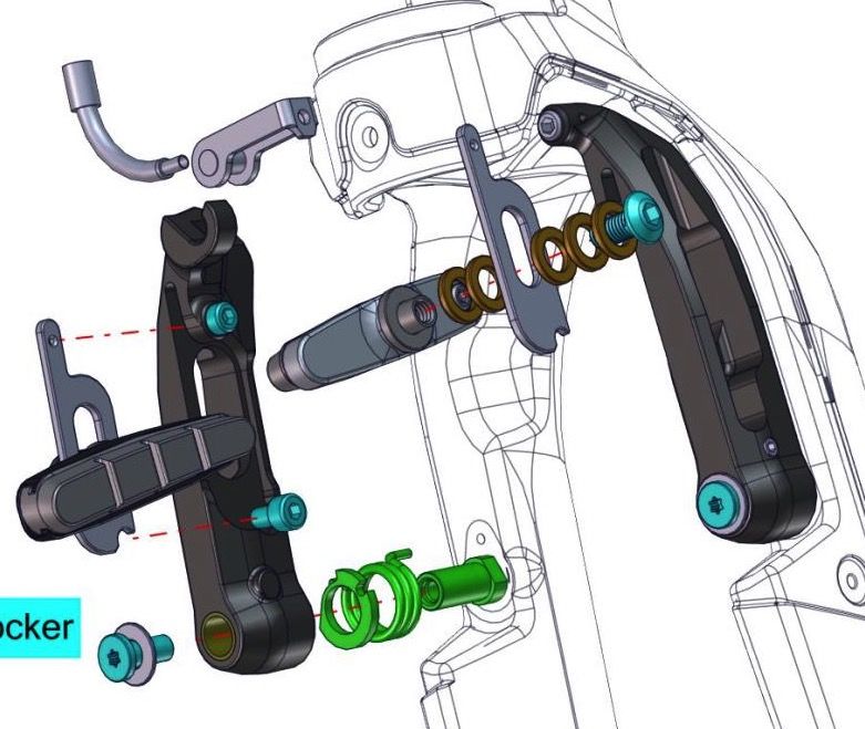
Contents
                                       General Notes and Warnings
                                       Tools
               General Assembly        Sizing and Fit
                                       P2P Configurations
                                       Headset Assembly
                                       V-Cockpit Pre-Assembly
           Cockpit-Specific Assembly
                                       Flat-Cockpit Pre-Assembly
                                       Brake Assembly & Installation
               Brake Assembly          Brake Booster Assembly & Brake Setup
                                       Right hand front brake assembly
                                       V-Cockpit Final Assembly
                                       Flat-Cockpit Final Assembly
              Finishing Assembly
                                       Seatpost and Extensions
                                       Frame Dropout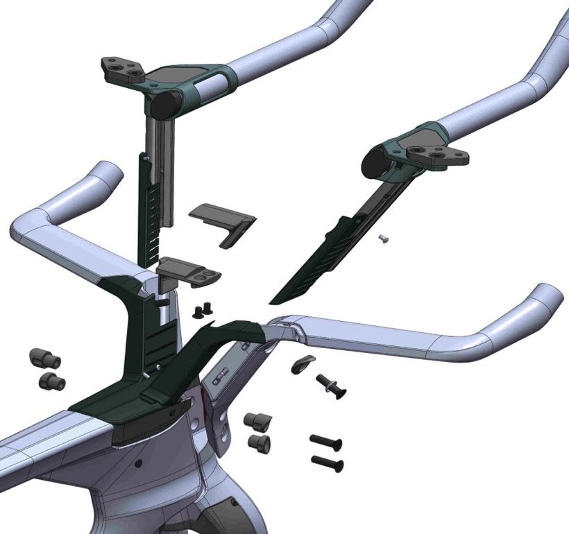
General Assembly Notes and Warnings

Due to the high level of integration of the Timemachine 01, proper assembly requires specialized tools and
a high degree of mechanical skill. It is critical that the assembly and maintenance is performed by a
qualified professional equipped with proper tools.
In order to successfully assemble the Timemachine 01, it is important to follow the order of operations
outlined in this guide. Failure to follow the outlined procedure can result in an assembly process that is
more difficult than necessary and an end product that performs less than ideal.

WARNING: The Timemachine is assembled using proprietary components that cannot be substituted with
non-specified equipment. Substitution of any of these components can compromise the integrity of the
entire system and should under no circumstances be substituted. Failure to follow this warning can result
in serious injury or death.
Tools and materials
  §   Allen keys: 2, 2.5, 3, 4, 5, 6, 10mm
  §   Torx keys: T10, T15, T25, T27
  §   Spanner wrench: 10,13mm
  §   High quality grease
  §   Carbon paste
  §   Torque wrench
  §   Carbon fiber cutting blade
  §   PF-86 BB Installation tool
  §   Shimano BB tool TL-UN66
  §   Dropout-style clamping work stand
  §   Zip ties
Sizing & Fit
Prioritize your performance

The new BMC Timemachine 01 has been designed with two unique and complimentary
integrated cockpits and two different seatpost mounting options - offering the widest range of
cockpit adjustment for a triathlon-specific bike.

It is strongly recommended that a final cockpit position is established prior to beginning the
assembly of your new Timemachine 01. We encourage the assistance of a qualified bike fit
specialist utilizing a fit bike, or the use of a pre-existing and functional position.

With a known “Armpad Stack and Reach”, BMC retailers can provide the proper assembly
procedure to ensure an end result that is integrated and functional.
Find your cockpit dimensions
                                                 Pad measurement

                        PR
                                       Horizontal: rear edge    Vertical: pad surface

              SH             PS              Seat height measurement

                                  HS

         BR
                                                 Vertical: top of saddle
                   BS                         Horizontal: fore/aft mid-point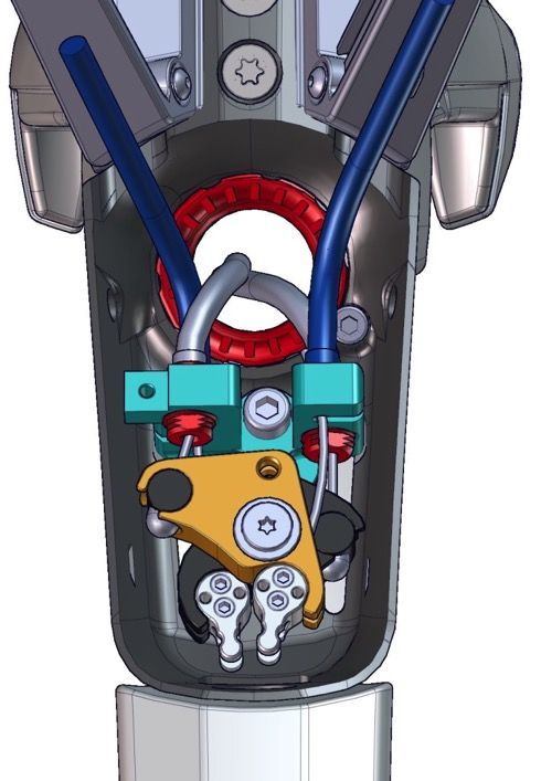
Find your cockpit dimensions

                                       Pad Stack & Reach
                        PR             Pad Stack = PS – BS
                                       Pad Stack =_________mm

                                       Pad Reach = PR – BR
              SH             PS        Pad Reach =________mm

                                  HS   Hand Stack = HS – BS
                                       Hand Stack =________mm
         BR
                                       Seat height =______mm
                   BS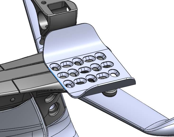
Find your cockpit dimensions
BMC Retailers are equipped with an online sizing resource to determine the ideal frame size,
cockpit suggestions, and assembly guidelines.

Sizing tool - https://b2b.bmc-switzerland.com/tools/timemachine-sizing

                 V-Cockpit                            Flat-Cockpit

     Examples of the BMC Dealer B2B online fit tool
P2P Configurations
Triathlon front-mount seatpost + storage box

           V-Cockpit                           Flat-Cockpit
Time trial rear-mount seatpost (no storage box)
V-Cockpit Flat-Cockpit
Due to the forward orientation, the V-Cockpit might exceed
UCI regulations for allowable cockpit lengthV-Cockpit vs Flat Cocpkit
V-Cockpit WHY: The V-Cockpit (spec on all complete bikes - frameset
optional) offers optimal aerodynamic performance for taller pad
stack dimensions, while the forward-offset promotes vertical
compliance – a state-of-the-art blend of high-performance and
comfort.
Note: For Time Trial athletes subject to UCI rules and regulations, the V-Cockpit
may exceed standard cockpit measurement guidelines.
Flat-Cockpit
WHY: The Flat-Cockpit offers maximal aerodynamic
advantage, allowing riders the lowest possible pad
stack configurations.Flat-Cockpit Configuration
The Flat-Cockpit can be mounted in 2 positions, pointing downward or upward. The
driving parameter to choose your position is the base bar altitude - depending on the
combination of your discipline, riding style and pad height. Orientation of the base
bar affects pad stack height by 10mm.
80mm
Note: the difference on base bar altitude is 80mm between the 2 positions.Seatpost Configuration
The seatpost has 2 mounting positions (patent pending), with multiple hardware
mounts – totaling 124mm of possible fore-aft adjustment.
71.5 ° – 80.8° Effective Seattube
(M-S @ 770mm)
4 mounting holes
62mm adjustment per post
The forward mounting option 120mm of range with overlap
enables the use of a storage box.Frame Assembly
Rear Seatpost Configuration

                 1

                             1   Seatpost

                             2   Cover – forward mount

                     2       3   Seatpost Clamp Cylinder (x2)
                         3   4   Seatpost Counterclamp Bolt & Washer
         4
                             5   Seatpost Clamp (Rear) & Bolts (x4)

         5                   6   Seatpost Counterclamp

             6               7   Seatpost ‘Play-Killer’ & Bolt

     7
Front Seatpost Configuration
1 1 Seatpost
2
2 Storage Box Cover
3 Rubber Link
3
4 Storage Box (optional)
5 Seatpost Clamp Nut (x2)
6 Seatpost Clamp Bracket & Bolts (x4)
4
5 7 Storage Box Fixation Mount & Bolt
Riders electing to not use the storage box can install an
optional cover in the vacant rear seatpost mounting hole.
6
7Electronic Junctions, Wires & Battery
Note: The Di2 Battery is installed in the rear seatpost mounting location – properly sized
foam will position the battery properly.
SM-EW90-B
SM-BCR2
SM-JC41Headset / Fork Components
1
2 1 Stopper Bolt
3 2 Headset Bolt
4
3 Fixation Bolts (x2: Front – Long / Rear – Short)
5 4 Brake Booster Box
11
6
12 5 Wavy Washer
7
13 6 Conical Compression Ring
7 Headset Bearing - Upper
8 8 Fork Bumper
9 Headset Bearing - Lower
9
10 Bearing Race
10
11 Multitool
12 Fixation Bolt
13 Di2 Junction BracketFork Installation
Step 1
1. Mount the Lower Conical Ring on the fork – slot pointing forwards.
2. Place the Lower Bearing into the frame – grease on all contact points Step 2
3. Insert the fork into the frame Step 3
4. Place the Upper Bearing into the frame – grease on all contact points Step 4Headset Assembly
5. Pre-assemble the Brake Booster Box:
a. Insert the Headset Bolt until the top of the Headset Bolt is 5mm Step a
from the bottom of the Brake Booster Box 5mm
b. Place the Wavy Washer over the Headset Bolt (from below) Steps
b&c
c. Place the Conical Compression Ring on the Wavy WasherHeadset Assembly
6. Install the assembled Brake Booster Box in to the Upper
Headset Bearing
Steps
6&7
7. Insert the Fixation Bolts (x2:
Front – Long / Rear – Short) to 12NmHeadset Assembly
8. Tighten the Headset Bolt to 8Nm using a Shimano Spline BB Tool
a. Check for play in the headset assembly
b. Tighten as necessary
Step 9
9. Install the Stopper Bolt 2 complete rotations
10. Rotate the Headset Bolt clockwise until closest indent aligns with Step 10
Stopper Bolt
11. Tighten Stopper Bolt to 4Nm Step 11Headset Assembly 12. Install Fork Bumper Step 12 Final check – test fore-aft play and ease of turning to verify headset is properly installed and adjusted.
Headset Adjustment
Each bike or frame is delivered with one Headset
Adjustment Tool, enabling adjustment of the Headset       Headset Bolt
                                                         Adjustment Tool
Bolt on an assembled bike (when cockpit/ cables are                        10mm Allen Key

mounted).

To adjust headset:
1. Unscrew the Stopper Bolt until clear of the Headset bolt
2. Insert the Headset Bolt Adjustment Tool
3. Turn clockwise (using a 10mm allen key in the tool)
4. Align Headset Bolt indent with the Stopper Bolt
5. Tighten the Stopper bolt to 4Nm
Brake Assembly & Installation
Brake Components
                                             1    Cable pipe
        1                3
            2                    4           2    Pipe holder
                                     5
                                             3    Quick pad holder
                                         6   4    Quick pad spacers (x5)

                                             5    Brake cartridge bolt
   12
                                             6    Brake arm (L & R)

                                             7    Brake boss

                                             8    Return spring
                11
                             7               9    Tension plate

                                             10   Mounting bolts

  10                     8                   11   Quick pad fixing bolt - lower
                     9
                                             12   Quick pad fixing bolt - upper
Brake Installation
1. Mount the Brake Bosses to the fork and the bottom of the
chainstays using thread locker and tighten to 6Nm
2. Mount the pre-assembled Brake Arms (L & R) to their
front/rear-specific locations using grease Step 2
3. Tighten Mounting Bolt to 6Nm grease
Mounting Bolt & washer > Brake Arm > Tension Plate > Return Spring > Brake BossV-Cockpit Assembly
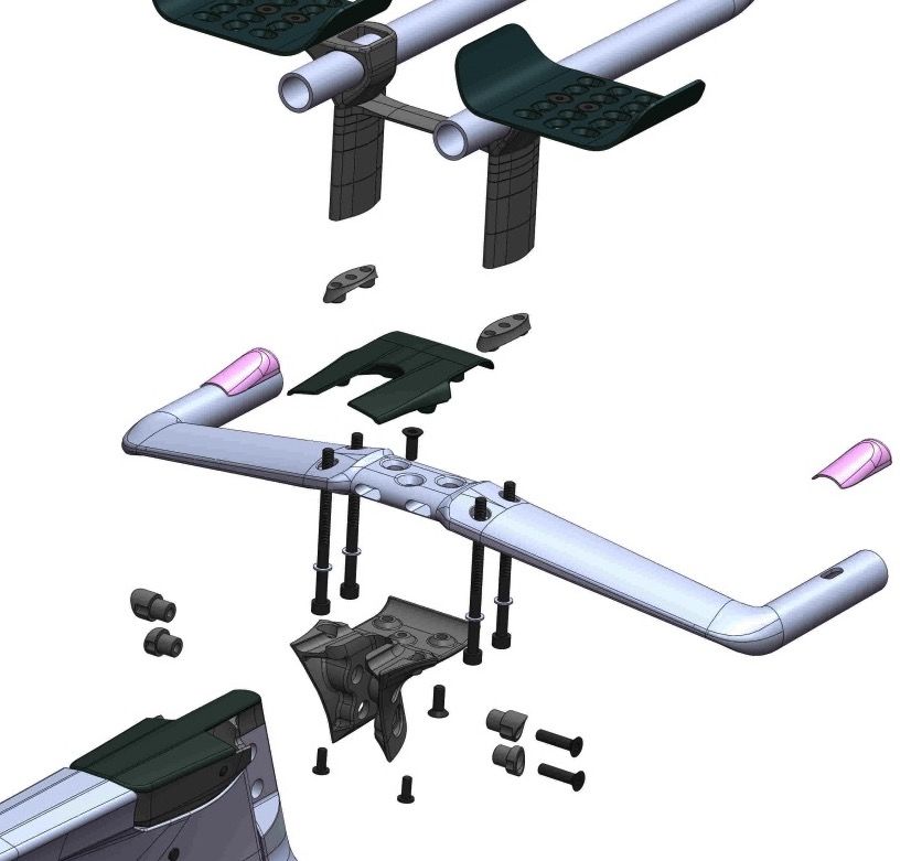
V-Cockpit Components
                                                 1   V-Covers (L&R)
                                                 2   Bridge (L&R)
                           Slider sub-assembly
                                                 3   Bridge fixation bolts (x2)
                                                 4   V-Covers (L&R)
                   1                             5   Slider fixing bolt - bolt washer & frame mount
                                                 6   Lateral fixing nuts (threaded) – Upper & Lower
           2                                                                         Upper nut - deep
                                                                                  Lower nut - shallow
               3
       4                                         7   Lateral fixing nut (non-threaded)
                                                                                     Upper nut - deep
   6                              5
                                                                                  Lower nut - shallow
                       7                         8   Lateral fixing bolts (x2)
                                      8
                                                                                     Upper bolt – long
                                                                                    Lower bolt – short
V-Cockpit Components
Slider sub-assembly (right)
2 1 Extension
2 Reach plate fixing bolts
3 5
1 3 Reach plate (optional)
4 4 Cover plate
5 Slider fixing bolts
6 Extension bracket
6
7 Extension clamp
9
7
8 Extension clamp bolt
8 9 End plug Dimension Stack range
SHORT: 90mm 0 – 22mm
10 Slider - short (x2) & long (x2) LONG: 124mm 29 – 50mm
10
Use the optional reach plate (3) for 22-29mm of altitude range.V-Cockpit Assembly – Extension Brackets
1. Insert the Extension Clamp into the Bracket (once installed, Step 1
the slider will hold the Extension Clamp in place)
2. Install the Slider into the Bracket and insert the Slider Fixation
Bolts Steps
2&3
3. Tighten up to 12 NmV-Cockpit Assembly – Extension Brackets
4. Remove the adhesive protection from the Cover Plate and put it in its
dedicated recess onto the Extension Bracket (Right/Left-specific) Step 4
5. Install the Extension Clamp Bolt into the Slider only
2 complete rotations
Step 5
6. Repeat steps 1-5 for the other side
The Carbon Extensions are now ready to be installed in later stepsV-Cockpit Assembly – Base Bar
Prepare the Base Bar (R & L) by pre-mounting:
1. Di2 wires (b)
2. Brake cable housing
Note: Failure to install Di2 wires before brake housing significantly
increases the difficulty of this process
Pre-cutting the cable housings:
Pre-cut length (mm)
Orientation
Shimano SRAM
EU: Rear Brake (R) 390 380
EU: Front Brake (L) 400 390 (a)
Right hand front brake assembly AUS / NZL / GB ect. (see page 50/51)
Rear Brake (L) 410 400
Front Brake (R) 420 410V-Cockpit Assembly – Base Bar
1. Install Sliders into the corresponding Base Bar (R & L)
2. Place the Spherical and V Washers onto the Slider
Fixation Bolts (x2) 1
4
3. Insert the Slider Fixation Bolts through the Base Bar
holes and the Slider longholes
4. Install the Slider Fixing Bolts into the corresponding 2
bridge parts (R & L) and pre-tighten them slightly (just 3
ensure the parts do not slide anymore)V-Cockpit Assembly – Base Bar 5. Assemble the Base Bar assemblies (R & L) together via the Bridge connection and the Bridge Fixation Bolts (x2) Note: Only tighten the Bridge Bolts enough to allow a small amount of play in Base Bars
Brake Booster
Assembly & Brake
     Setup
Brake Booster – What is it?
The Brake Booster (patent pending) is a proprietary system to
enhance Timemachine 01 brake performance.
Functions
1. Increase Lever Pull : Free Stroke ratio
Why: prevent unwanted brake pad rub during wheel flexing
moments
2. Enable the brake cables to be disconnected
Why: allows athletes to disconnect the cockpit from the frame
for traveling/packingBrake Booster Components
Brake Boosters will come pre-assembled on the Support (10) on all complete bikes and framesets.
1 1 Upper bolt
2
2 Washer
3
3 Cable interface
4
13 5
4 Brake Booster – Upper (R)
12 5 Main Socket Bolt
11 3
13 6 Brake Booster – Lower (F)
6
12 7 7 Housing boss (x2)
11
8 Brake Booster Box
10
9 Countersunk Bolt
10 Support
11 Bushing
8 12 Cable Stopper (x2)
9
13 Cable Stop Nuts (x2 per stopper)Brake housing & Cable Installation
Temporarily removing the Brake Booster Box will provide service
technicians more space to work!
1. Remove the Main Socket Bolt (M5)
2. Rotate the fork to expose the bottom of the Brake Booster Box
Steps
3. Remove the Countersunk Bolt from below. 1-3Brake housing & Cable Installation
Pre-cut brake housing lengths:
Frame Brake Casing Length
Size Front Brake Rear Brake
S 120mm 710mm
M-S 135mm 740mm
M-L 135mm 770mm
L 175mm 840mm
Failure to follow these prescribed lengths will significantly increase
the difficulty of achieving proper brake function and smooth feel.Brake Housing & Cable Installation
1. Starting at the Brake Booster Box, route the brake housing through the Step 1
Headset Bolt using the supplied routing liner.
2. Pass the front brake housing directly through the head tube to the
mounted brake caliper
Step 2
3. Pass the rear brake housing in to the frame at the downtube junction
and pass it underneath the bottom bracket area to the mounted brake
caliper. Step 3Brake Housing & Cable Installation
Brake Booster Brake Calipers
1. Prepare the Brake Booster for the next steps by centering the
position of the Housing Boss (same distance front and back) Step 1
2. Mount the brake cables at the Brake Booster to the brakes Cable Interface
using Cable Interfaces.
Step 2Brake Housing & Cable Installation
Brake Lever Brake Booster
1. Install brake cables at the brake levers and pass cable
Housing
completely through the housing
2. Install Stoppers on the cable ends exactly 32mm from the end Ferrule
of the ferrule (ensure the brake cable is taut for accurate
measurement)
32mm
3. Tighten the Stopper Bolts to 3Nm
4. Trim remaining cable StopperBrake Housing & Cable Installation
1. Mount the pre-assembled V-Cockpit or Flat-Cockpit to the
fork by sliding the cockpit downward and rearward. Step 1
2. When mounting the cockpit to the fork, it is critical to properly
align the Lateral Fixing Nuts with the corresponding notch in
the cockpit - as indicated in the image. Steps
2&3
3. Tighten the Lateral Fixing Bolts to 8NmBrake Housing & Cable Installation
3. Attach all brake cables to corresponding Brake Booster
locations Step 3
a. Upper assembly = Rear brake
b. Lower assembly = Front brake
4. Route brake cables to brake calipers (if not already done)
5. Install the Support on the Brake Booster Box using the Main Step 5
Socket Bolt and the Countersunk Bolt (from below)Brake Caliper Setup 6. Set the Brake Booster to ‘zero’ by aligning the upper and lower arms such that there is a visible hole alignment. Insert a 3mm allen key through the holes to hold their neutral position (as seen in subset image) Step 6 7. Begin brake caliper setup Right hand front brake assembly AUS / NZL / GB ect. see page 50/51
Right hand front brake assembly
Routing the front break on the right side of the TM01 is possible.

The following pages demonstrate how to change the brake cable
routing to assemble the front brake for right-handed shifting.

                                                 The differences in the cable routing exist
                                                 only between the brake lever and the brake
                                                 booster (in blue).

                                                 The rest of the cable routing (in green)
                                                 between the brake lever and the brake
                                                 caliper, needs no modification.

       In green the standard routing from
       the brake booster to the brake caliper.
       In blue the new routing.
Right-hand front brake assembly
Housing length: The cables housings have to be cut at the correct lengths (see page
36).
Cables routing: The cables can be routed in the brake booster like on the standard
assembly (see page 39-57). Temporary removing the brake booster mechanism from the
converter box will provide more space to work.
Pay attention to cross the housing correctly, the correct paths of the housing is shown
below.
The distance from end of casing to brake stoppers have to be
32mm (see page 46).
Reinstall the brake booster in the converter box.
The correct routing of the housing in converter box:
Red front brake / Blue rear brake
Green standard assemblyBrake Caliper Setup
8. With Brake Calipers installed, set the caliper to
a pre-defined spacing, as follows: 20
Step 8
22
Front Rear
20mm 22mm FRONT REAR
One objective of this step is to align the brake caliper and frame, as seen in the
frame & caliper
image – small adjustments of provided measurements might be necessary.
(Following this guideline will help ensure the Front Caliper Cover does not
interfere with the caliper function.)
alignmentQuick Pad – What is it?
The Quick Pad feature (patent pending) is an easily removable brake pad
cartridge system available only on Timemachine 01.
Function
1. Increased adaptability
Why: allows multiple wheelsets to have pre-assembled brake pad
components, regardless of rim width or brake track height
2. Decrease service complexity
Why: by providing each bike with 2 pair of Quick Pad cartridges,
riders can set up properly spaced cartridges for 2 wheelsets (racing
& training) with minimal effortBrake Housing & Cable Installation
Quick-Pad assembly guideline
Brakeset washer assembly
Rim Width Brake Inboard (A) Outboard (B) Pad nut
F 1 5 12mm
28mm
R 0* 5 10mm**
F 2 4 12mm
26mm
R 0 5 10mm**
F 3 3 12mm
24mm
R 1 4 10mm**
F 4 2 12mm
22mm
R 2 3 10mm**
F 5 1 12mm
20mm
R 3 2 10mm
F 6 0 12mm
18mm
R 4 1 10mm
* Use narrow brake pads (ZIPP Tangente Platinum Pro Evo, SwissStop Flash EVO Black Prince )
** Depending on small chainring size, it might be needed to install the 7.5mm nut and remove some washers from the outboard side
to avoid collisionBrake Housing & Cable Installation
9. With the caliper arm spacing set up as described previously,
arrange the spacers on the Quick Pad unit Step 9
10. Mount the Quick Pad unit on to the Brake Caliper using the Quick
Mount Fixing Bolts (upper & lower)
Step 10
11. Adjust pads as usual and verify the proper amount of free stroke
at the brake lever.Brake Housing & Cable Installation
Repeat Steps 9 & 10 for alternate wheelset
Note: always maintain the full number of spacers
(x6 front / x5 rear) to ensure proper thread
Note
engagement of the cartridge – only the orientation
of the spacers changes.
~4mmBrake Housing & Cable Installation 10. Install Brake Caliper Cover (front) Step 10
Finishing Assembly – V-Cockpit Extensions

1. Install uncut extensions in your chosen cockpit.
2. Determine your preferred position of extension.                  Step 3

3. Mark extension at rear edge of clamp, as seen in image right.

4. Cut extension to proper length using the included cutting tool   Step 4
   – cutting tool will ensure proper angled cut.
Finishing Assembly – V-Cockpit Extensions
1. Install properly cut extension in to Extension Clamp

2. Tighten Extension Bolt to 4Nm                                    Step 2

3. Install Extension End Caps (end caps have a slotted bottom for
   passing electronic wires)                                        Step 3
Finishing Assembly – V-Cockpit
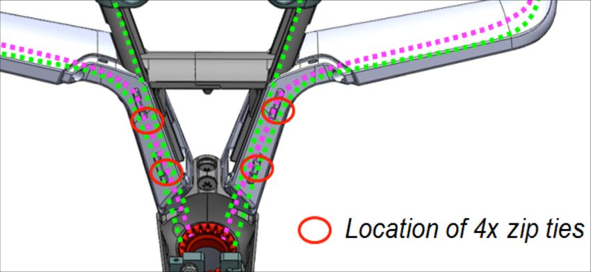
4. Secure Di2 wires and brake housing with (x4) zip ties Step 4
on to the vertical arms
5. Cut Slider Covers to match the slider extension length
Steps
5&6
6. Fix Slider Covers with small M3 bolt
cutFinishing Assembly – V-Cockpit
6. Secure Lower Covers at (x5) mounting points –
identified in image right Step 6
Step 7
7. Secure Lower Covers using an M3 boltFinishing Assembly – V-Cockpit
8. Install optional Reach Plate as required for desired Step 6
position
60mm
Note: The optional Reach Plate can be positioned in multiple Note
configurations and also offers 7mm of vertical “stack” to 25mm
complete ideal “pad stack & reach”Finishing Assembly – V-Cockpit 9. Install Armrests as required for proper Reach
Flat-Cockpit
 Assembly
Flat-Cockpit Components
                                    1    Stack spacers

                                    2    Spacer interface

                                    3    Flat-Cockpit cover
                            1
                                    4    Central bolt

                                    5    Cover front bolts (x2)
    13                  2
                                    6    Upper nut
                    3
                4                   7    Lower nut
   12
                                    8    Lateral fixing bolts (x2)
    11
                                    9    Cover rear bolts
   10                               10   Upper and lower threaded nut
                            5
                                6   11   Flat bar base adapter

                                    12   Bracket bolts and washers (x4)
                                8
                    7               13   Hand stopper (x2)
           9
Flat-Cockpit Assembly – Base Bar
Prepare the Base Bar (R & L) by pre-mounting:
1. Di2 wires
2. Brake cable housing
Note: Failure to install Di2 wires before brake housing
significantly increases difficulty of this process
Pre-cutting the cable housings:
Pre-cut length (mm)
Orientation
Shimano SRAM
EU: Rear Brake (R) 390 380
EU: Front Brake (L) 400 390
Right hand front brake assembly AUS / NZL / GB ect. (see page 50/51)
Rear Brake (L) 410 400
Front Brake (R) 420 410Finishing Assembly – Flat-Cockpit Extensions
1. Determine necessary “pad stack” height and create required
spacer and bolt length combination
Spacer Altitude (mm) Bolt Length (mm) Bridge Required?
70 95
65 90
60 85
YES
55 80 Bridge
50 75
45 70
40 65
35 60
30 55
25 50
20 45 NO
15 40
10 35
5 30
0 25Finishing Assembly – Flat-Cockpit Extensions 1. Determine necessary “armpad reach” and place the adapter orientation to accommodate preferred position Step 1 (by changing left and right side)
Finishing Assembly – Flat-Cockpit Extensions
1. Install uncut extensions in your chosen cockpit

                                                                    Steps
2.   Determine your preferred position of extension                  1-3

3. Mark extension at rear edge of clamp

                                                                    Step 4

4. Cut extension to proper length using the included cutting tool
   – cutting tool will ensure proper square cut
Finishing Assembly – Flat-Cockpit Di2 1. After cockpit is fully assembled arrange Di2 wires Step 1 as seen in the image 2. Install Flat Cover, making sure to prevent any unwanted Step 2 pinching of electronic wires.
Finishing Assembly – Di2 Junction Box
1. Di2 wires will route from the cockpit through the Headset
Bolt and enter the frame Step
1&2
2. Route the wires from the frame up through the Di2 port
in the top tube (hidden under Brake Booster)
3. Connect the shifting wires to the Junction Box
4. Mount the Junction Box to the Junction Box Mount Steps
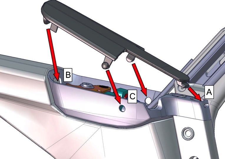
5. Install the Junction Box Mount to the frame 3-5Finishing Assembly – Di2 Junction Box 6. Mount the Brake Booster Box Cover by inserting Tab A, followed by the remaining Step 6 tabs until cover is secure
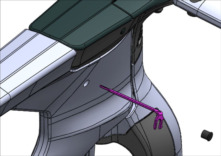
Finishing Assembly – Di2 Junction Box

Note: The Di2 Junction Box is accessible through a
frame port on the drive side of the box – the provided   Note
Multi-Tool can be used for shift adjustment purposes,
as seen in figure.
Finishing Assembly – Di2 Junction & Battery

Note: The Di2 Battery is installed in the rear seatpost mounting location – properly sized
foam will position the battery properly.

                                  SM-EW90-B

                        SM-BCR2

                                   SM-JC41
Finishing Assembly – Multi-Tool
1 Multi-Tool - 5 functions:
1. Adjust brake cable tension (pad wear) 2 1
2. Remove cable stoppers @ Booster Box
(disassembling) 3
Tool
3. Push the Di2 junction button (adjustment) 5 4 storage
4. Check SP insertion minimum
5. Remove rear Storage BoxFinishing Assembly – Flat-Cockpit Mechanical
1. For mechanical shifting, the Flat Cover must be modified for
cable and housing entry Step
1&2
2. Using the two pre-drilled indents (image), drill from the back side
of the cover to create 5mm holes
3. Install Flat Cover, making sure to prevent any unwanted pinching
of electronic wires.
4. Install Flat Cover Rear Bolts to 5Nm Steps
3-5
5. Install Flat Cover Front Bolts to 10NmFit & Finish: Seatpost / Extensions
Finishing Assembly – Rear Mount Seatpost

                   2
       1
                           1   Seatpost

                           2   Front Cover
                       3
       8                   3   SP Clamp Cylinders (x2)

                           4   SP Play Killer & Bolt

                           5   SP Counterclamp
   7
           6               6   SP Clamp - Rear

               5           7   SP Clamp Bolts (x4)

                           8   SP Counterclamp Bolt & Washer
    4
Finishing Assembly – Seatpost
1
1 Seatpost
2 SP Clamp Cylinders (x2) 6
2
3 SP Clamp Bolts (x4)
3
4 SP Clamp - Front
4 5 SP Cover - Rear
6 Brake – Lower (F)
Booster
5
6 Storage Box
7 Storage Box Fixing Bolt & Knob
7Finishing Assembly – Seatpost
1
2
1 Main bolt
3
2 Washer
4 3 Top Clamp
5 4 Bottom Clamp
5 Support
Cutting toolFinishing Assembly – V-Cockpit Extensions
1. Install uncut extensions in your chosen cockpit.
Step 3
2. Determine your preferred position of extension.
3. Mark extension at rear edge of clamp, as seen in image right.
4. Cut extension to proper length using the included cutting tool –
cutting tool will ensure proper angled cut. Step 4Finishing Assembly – Flat-Cockpit Extensions
1. Install uncut extensions in your chosen cockpit.
Steps
2. Determine your preferred position of extension. 1-3
3. Mark extension at rear edge of clamp
4. Cut extension to proper length using the included cutting tool
– cutting tool will ensure proper square cut Step 4Adjustable Dropouts
&
Derailleur HangerFinishing Assembly – Adjustable Dropout & Hanger
1 Dropout Dial
2 Derailleur hanger
1
3 Sliding Dropout Adjuster
2 4 Derailleur Hanger Bolts
3
4Finishing Assembly – Adjustable Dropout & Hanger The adjustable, full-carbon horizontal dropouts allow 10mm of fore-aft adjustment, allowing riders to place the rear tire in close proximity to the frame, depending on preferred tire size (maximum 27mm).
BMC Timemachine Resources
Website
www.bmc-switzerland.com/timemachine

Assembly manuals
www.bmc-switzerland.com/timemachine/manual

Sales App
salesapp.bmc-switzerland.com

b2b Sizing Tool
https://b2b.bmc-switzerland.com/tools/timemachine-sizing
Retailer-friendly packaging
                                                   1
                                                       3

                                                       4           7
                                                               6
                                                   2
                                                           5

1   Seatpost
2   Owner’s manual
3   Extension
4   Standard bicycle accessories for safe riding
5   Extension
6   Some stuff needed for triathlon
7   Some other stuff needed…..
Retailer-friendly packaging 1. Remove all small parts and bike 2. Remove all packaging 3. Install seatpost 4. Install wheels 5. Install extensions (p. 36 & 57 Timemachine Assembly Manual) 6. Wrap handlebars and extensions 7. Verify proper brake and shifting function, adjust as needed 8. Safety (torque) check 9. Find a spot to highlight your new Timemachine!
You can also read