TWO INDEPENDENT RADIOS IN THE SMALLEST ANTENNA FOOTPRINT - DUO mXTENDTM: USER MANUAL DUO mXTENDTM (NN03-320) - Ignion
←
→
Page content transcription
If your browser does not render page correctly, please read the page content below
TM
DUO mXTEND :
TWO
INDEPENDENT
RADIOS IN THE
SMALLEST
ANTENNA
FOOTPRINT

USER MANUAL
DUO mXTENDTM (NN03-320)
USER MANUAL
                                              DUO mXTENDTM (NN03-320)

DUO mXTENDTM
Two independent radios in the smallest antenna footprint

Last Update: January 2021                                               2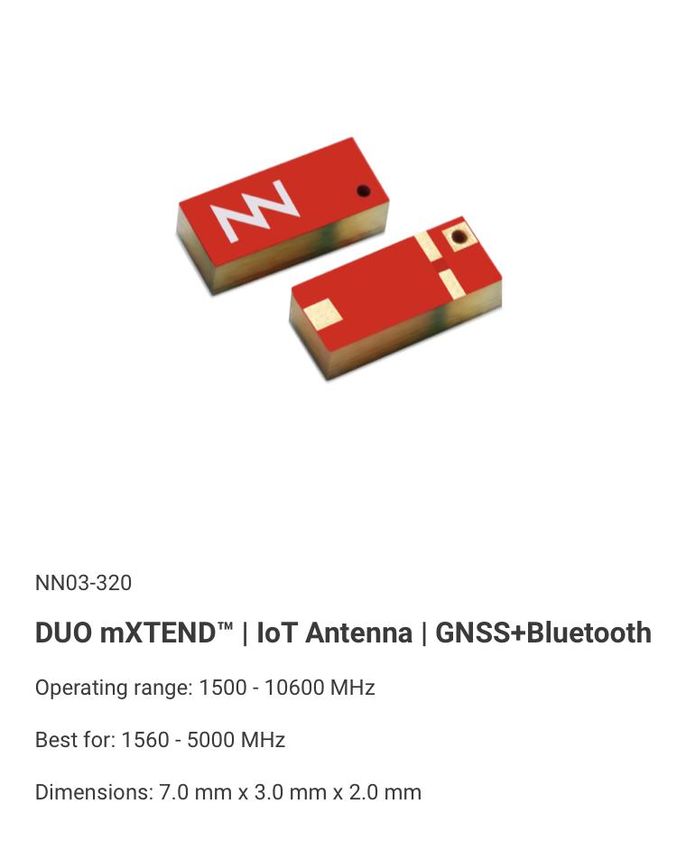
USER MANUAL
                                                                   DUO mXTENDTM (NN03-320)

What is DUO mXTEND?

DUO mXTEND is a dual-port, chip antenna component designed to embed up to two
independent radios in the smallest antenna footprint. The chip is designed to combine, for
example, Bluetooth and GNSS or Wi-Fi and GNSS into a single package. Due to its Virtual
Antenna technology, DUO mXTEND can feature many other wireless services, such as UWB
making it the ideal antenna part for indoor/outdoor tracking devices.

DUO mXTEND has been engineered so that usually no ground clearance around the
component is required. Only a minimum clearance underneath the exact footprint of the
component is needed to obtain the best radiation efficiency in most cases. Moreover, the
component has been designed for dual-mounting: either at the center edge of your device or
at a corner, making this antenna flexible and easy to adapt in a variety of devices and radio
configurations.

                       TOP                                       BOTTOM

                   7.0 mm

        2.0 mm

         3.0 mm

What is DUO mXTEND for?

DUO mXTEND current operating range extends form 1500 MHz up to 10.600 MHz, making it a
versatile component to cover any radio application within that range, including Bluetooth, Wi-
Fi, and UWB, but also 5G and CBRS. Its miniature and slim form factor, together with its no-
ground clearance and dual-mounting features makes it the ideal wireless connectivity chip
for small indoor/outdoor tracking devices and all kinds of miniature IoT sensors. Due to the
minimum footprint and size of the DUO mXTEND, embedded massive MIMO (e.g. 8 x 8) devices
are a good application, where the density of installed antennas in a PCB is inherently high.

    ▪    IoT Asset Trackers                       ▪   Notebooks/Tablets
    ▪    5G Routers (MIMO)                        ▪   Health sensors
    ▪    Wi-Fi Routers (MIMO)                     ▪   Animal Trackers
    ▪    Environmental Sensors                    ▪   IoT Developer Kits
    ▪    Personal Gadget Tracker                  ▪   Smart City sensors
    ▪    Indoor Trackers

Last Update: January 2021                                                                        3
USER MANUAL
                                                                    DUO mXTENDTM (NN03-320)

What differentiates DUO mXTEND from other chip antennas?

Like every other Virtual AntennaTM product, DUO mXTEND is frequency neutral, meaning that
its frequency response is not determined by the antenna component but designed by the
electronics engineer through a simple matching circuit. Virtual AntennaTM technology enables
packaging the desired multiband performance in the smallest ever form factor, which enables
the whole mXTEND range of components featuring a tiny off-the-shelf, surface-mount (SMD)
electronic chip package. That makes mXTEND components easy to be integrated in about any
IoT device through a shorter and easier design cycle and a much more robust, reliable and costs
effective manufacturing process.

In addition, DUO mXTEND is one of the Virtual AntennaTM products featuring VariantTM
technology, which enables embedding multiple antenna boosting elements into a single
chip. By embedding both an independent electric and magnetic booster, the chip features two
independent ports/feeds that enable sharing the same antenna component by two different
radios. This, together with the no-ground clearance and dual-mounting features, the DUO
mXTEND provides all the flexibility needed to develop nearly any wireless device fast. Use the
DUO mXTEND for any wireless IoT or mobile product and save critical space on your PCB, as
it covers multiple radio needs for many IoT applications, including, GNSS, or Bluetooth, Wi-Fi,
UWB and the high bands of 5G and CBRS, to name a few.

Last Update: January 2021                                                                         4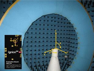
USER MANUAL
                                                    DUO mXTENDTM (NN03-320)

Click and select an application that fits your project:

DUO mXTEND USING TWO PORTS                          (1500 MHz – 2500 MHz)
GNSS + Bluetooth IoT TRACKER

DUO mXTEND FOR 5G                                   (3400 MHz – 3800 MHz)
                                                    MHz)

DUO mXTEND FOR UWB                                   (3100 MHz –10600 MHz)
                                                     MHz)MHz)

Click to view other useful DUO mXTEND guidelines:

HOW TO EMBED A VIRTUAL ANTENNA

MECHANICAL SPECIFICATIONS

ASSEMBLY AND MANUFACTURING

PACKAGING

Last Update: January 2021                                                     5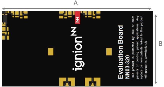
USER MANUAL
                                         DUO mXTENDTM (NN03-320)

Chapter Index
1.   HOW TO EMBED A VIRUTAL ANTENNA……………………………………....…..6

2.   DUO mXTEND TWO-PORT IoT TRACKER…………………………………………8

3.   DUO mXTEND FOR 5G………………………………………………………………15

4.   DUO mXTEND UWB………………………………………………………………….20

5.   MECHANICAL SPECIFICATIONS………………………………………………….25

6.   ASSEMBLY AND MANUFACTURING……………………………………………..28

7.   PACKAGING……………………………………………………………………..……30

Last Update: January 2021                                          6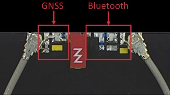
USER MANUAL
                                                                   DUO mXTENDTM (NN03-320)

How to embed a Virtual Antenna
Design with Virtual Antenna in 1-2-3

                                    STEP 1: Place the antenna component

                                        1. Select one corner of your PCB
                                        2. Ensure your ground plane meets the DUO
                                           mXTEND clearance area restrictions
                                        3. Respect a keep out space around the booster.
                                           Keep at least 5mm distance from metallic objects

                                    Look here for an example on placing the DUO mXTEND

 STEP 2: Design your matching network

     1. Through a combination of inductors & capacitors
        obtain 50 Ohms of antenna impedance to optimize
        the transfer of energy to your antenna
     2. It is critical to fine-tune your MN throughout the
        entirety the design process of achieve your desired
        frequency response

 Look here for an example of a matching network we found in
 an DUO mXTEND application via simulation

                                  STEP 3: Test your device

                                     1. Perform a field test in which your antenna is placed
                                        in its final housing. Fine-tune the MN if needed.
                                     2. Use a network analyzer to adjust mismatch
                                     3. Test the antennas efficiency with an anechoic
                                        chamber

                                  Look here for testing we did on our Evaluation Board, with
                                  the DUO mXTEND integrated in our Anechoic Chamber

                                                       Scan QR code to
                                                         be taken to our
                                                    videos highlighting
https://www.ignion.io/tutorials
                                                       these three easy
                                                                   steps

Last Update: January 2021                                                                      7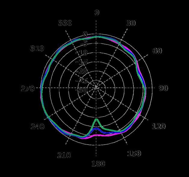
USER MANUAL
                                                                       DUO mXTENDTM (NN03-320)

       Need further help? Easy start with NN Wireless Fast Track

Do you need more help with your antenna for your device?

Use our NN Wireless Fast Track service and get your ready-to-test antenna design
especially simulated for your platform free of charge1, and in 24 hours.

         1. Fill out the form, submit it and receive a confirmation email.
         2. Reply to the email. If you wish, attach any relevant design file.
         3. Get your design in 24h.

         https://www.ignion.io/fast-track-project/

                            Scan QR code
                            to be taken to
                            our Wireless
                            Fast Track
                            page

Last Update: January 2021                                                                        8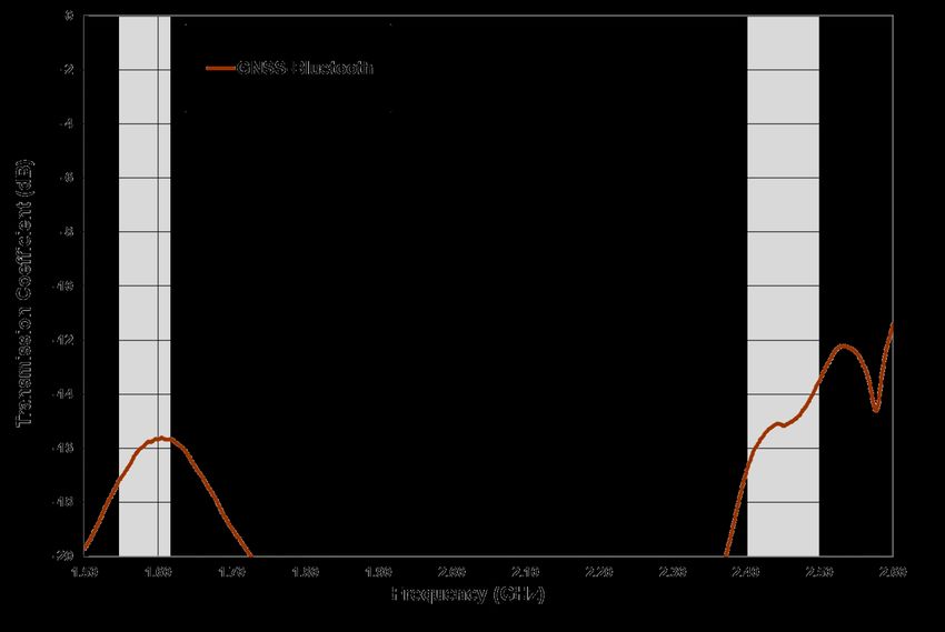
USER MANUAL
DUO mXTENDTM (NN03-320)
DUO mXTEND USING TWO PORTS
GNSS and Bluetooth in a Single Package
The DUO mXTENDTM antenna booster has been specifically designed for providing worldwide
Global Navigation Satellite Systems (GNSS) and Bluetooth (BT) performance in wireless
devices with small space requirements. Here we will compare BeiDou, GPS & Galileo and
GLONASS performance operating in conjunction with Bluetooth. Using one of our Evaluation
Boards, an example of a common DUO mXTEND™ placement is seen. Finally, two different
matching networks are selected, using both ports, for both GNSS and BT, allowing us to test,
obtain, and analyze the VSWR, total efficiency, gain and radiation patterns.
QUICK REFERENCE GUIDE
Technical BeiDou GPS & GALILEO GLONASS Bluetooth
features 1561MHz 1575MHz 1598 – 1606MHz 2400 – 2500MHz
Average
> 40% > 45% > 50% > 50%
Efficiency
Peak Gain -1.1 dBi -1.0 dBi -1.0 dBi -0.9 dBi
VSWR < 3:1
Radiation Pattern Omnidirectional
Polarization Linear
Weight (approx.) 0.11 g.
Temperature -40 to +125 ºC
Impedance 50
Dimensions
7.0 mm x 3.0 mm x 2.0 mm
(L x W x H)
Table 1 – Technical Features. Measures from the Evaluation Board. See Error! Reference source not
found..
Last Update: January 2021 9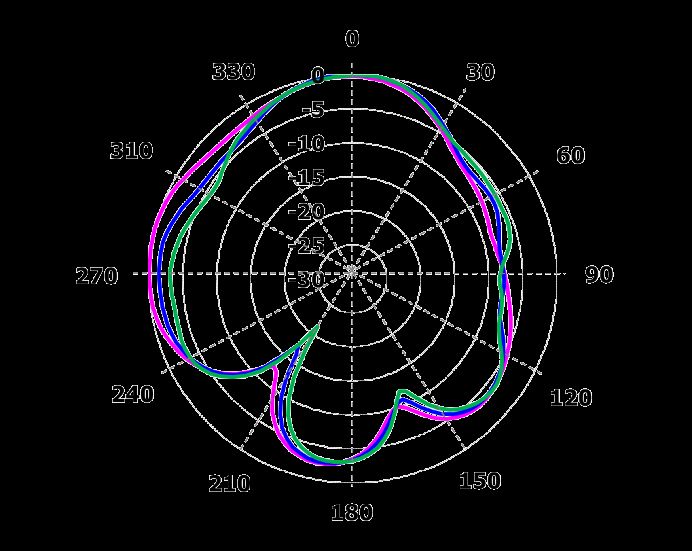
USER MANUAL
                                                                      DUO mXTENDTM (NN03-320)

ELECTRICAL PERFORMANCE
EVALUATION BOARD
This Evaluation Board (part number: EB_NN03-320-m-GNSS-BT) integrates one DUO
mXTENDTM antenna booster to provide operation in four frequency regions, 1561MHz (BeiDou
E1 band), 1575 MHz (GPS L1 band and GALILEO E1), from 1598 MHz to 1606 MHz (GLONASS
L1 band) and from 2400 MHz to 2500MHz (Bluetooth). A couple of UFL cables connect this dual
input/output port solution to the SMA connectors for testing purposes.

                                                                           Measure       mm
                                                                             A           80
                                                                             B           40
                                                                           Tolerance: ±0.2 mm
                                                                     Material: The Evaluation Boards
                                                                     are built on FR4 substrate.
                                                                     Thickness is 1 mm.

 Figure 1 – EB_NN03-320-m-GNSS-BT Evaluation Board providing operation at BeiDou E1 band (1561
 MHz), GPS L1 band and GALILEO E1 band (1575 MHz), GLONASS L1 band (from 1598 MHz to 1606
 MHz) and Bluetooth (from 2400MHz to 2480MHz). Notice that the clearance area is equal to the DUO
 mXTENDTM footprint.

This product and its use are protected by at least one or more of the following patents and patent
applications PAT. US 62/529032; and other domestic and international patents pending.
Additional information about patents related to this product is available at www.ignion.io/virtual-
antenna/.

Last Update: January 2021                                                                             10
USER MANUAL
DUO mXTENDTM (NN03-320)
MATCHING NETWORK
DUO mXTENDTM needs two matching networks to connect to your device, a first for the
Bluetooth port, a second for the GNSS one (Error! Reference source not found.). This section
describes in (Error! Reference source not found.) a suitable matching network for DUO
mXTENDTM and the resulting product specs when measured in the reference evaluation board
(EB_NN03-320-m-GNSS-BT) described in the previous section. Please note that different
tracking devices with different form factors, RF ground planes and nearby components may
need a different matching network. If you need assistance to design your matching network,
please contact support@ignion.io, or try our free-of-charge NN Wireless Fast-Track design
service, you will get your chip antenna design including a custom matching network for your
device in 24h1. Other related to NN’s range of R&D services is available at:
https://www.ignion.io/rdservices/
Figure 2 – Matching network distribution in the Evaluation Board (Error! Reference source not
found.).
1561 MHz – 1606 MHz and 2400 MHz – 2500 MHz
1 See terms and conditions for a free NN Wireless Fast-Track service at: https://www.ignion.io/fast-track-project/
Last Update: January 2021 11USER MANUAL
DUO mXTENDTM (NN03-320)
2.4nH
0.7pF
DUO
Value Part Number
mXTENDTM
2.4 nH LQW15AN2N4C00
2.0pF
MN GNSS 2.0 pF GJM1555C1H2R0WB01
2.8pF 0.7 pF GJM1555C1HR70WB01
2.8 pF GJM1555C1H2R8WB01
0Ω 4.7nH 0Ω
DUO
mXTENDTM Value Part Number
0Ω -
MN BT 4.7 nH LQW15AN4N7G80
4.7nH
4.7 nH LQW15AN4N7G80
0Ω -
Figure 3 – Matching network implemented in the Evaluation Board 1 port (Error! Reference source
not found.).
To ensure optimal results, the use of high-quality factor (Q) and tight tolerance components is
highly recommended (e.g. Murata components with part numbers as in Error! Reference
source not found.). The antenna performance is always conditioned by its operating
environment so that different devices with different printed circuit board sizes, components
nearby the antenna, LCD’s, batteries, covers, connectors, etc. affect the antenna performance.
Accordingly, it is highly recommended placing pads compatible with 0402 and 0603 SMD
components for a matching network as close as possible to the feeding point of the antenna
element. Do it in the ground plane area, not in the clearance area. By tuning the matching
network in your final design with your final surrounding components (batteries, displays,
covers, etc.) you will be able to optimize the antenna performance without changing the
antenna part.
VSWR AND TOTAL EFFICIENCY
VSWR (Voltage Standing Wave Ratio) and Total Efficiency versus Frequency (GHz).
Last Update: January 2021 12USER MANUAL
DUO mXTENDTM (NN03-320)
Figure 4 – VSWR and Total Efficiency at BeiDou E1 band (1561 MHz), GPS L1 band and GALILEO
E1 band (1575 MHz), GLONASS L1 band (from 1598 to 1606 MHz) (from the Evaluation Board) (Error!
Reference source not found.).
Figure 5 – VSWR and Total Efficiency for the 2400 – 2500 MHz (from the Evaluation Board) (Error!
Reference source not found.).
TRANSMISSION COEFFICIENT
Last Update: January 2021 13USER MANUAL
DUO mXTENDTM (NN03-320)
Figure 6 – Transmission coefficient between GNSS (1561 – 1606 MHz) and Bluetooth (2400 – 2500
MHz) from the Evaluation Board (Error! Reference source not found.).
Last Update: January 2021 14USER MANUAL
DUO mXTENDTM (NN03-320)
RADIATION PATTERNS (1561MHz, 1575MHz, and 1598 -
1606MHz), GAIN AND EFFICIENCY
0
330 0 30
-5
310 -10
60
-15
-20
-25
270 -30 90
240 120
210 150
180
Measurement System Set-Up = 90º Plane XY at 1.561 GHz, 1.575 GHz
Evaluation Board in Plane XY and 1.602 GHz
0 0
330 0 30 330 0 30
-5 -5
310 -10 310 -10
60 60
-15 -15
-20 -20
-25 -25
270 -30 90 270 -30 90
240 120 240 120
210 150 210 150
180 180
= 0º Plane XZ at 1.561 GHz, 1.575 GHz = 90º Plane YZ at 1.561 GHz, 1.575 GHz
and 1.602 GHz and 1.602 GHz
Gain -1.1 dBi
BeiDou
Efficiency 44.6 %
Gain -1.0 dBi
GPS
Efficiency 49.7 %
Peak Gain -1.0 dBi
Gain Average Gain across the band -1.0 dBi
Gain Range across the band (min, max) -1.0 -1.0 dBi
GLONASS Peak Efficiency 54.6 %
Efficiency Average Efficiency across the band 53.9 %
Efficiency Range across the band (min, max) 53.0 – 54.6 %
Table 2 – Antenna Gain and Total Efficiency from the Evaluation Board (Error! Reference source not
found.) for BeiDou E1 (1561 MHz), GPS L1 (1575 MHz) and GLONASS L1 (1598 MHz – 1606 MHz)
bands. Measures made in the Satimo STARGATE 32 anechoic chamber.
Last Update: January 2021 15USER MANUAL
DUO mXTENDTM (NN03-320)
RADIATION PATTERNS (2400 - 2500 MHz) GAIN, AND
EFFICIENCY
0
330 0 30
-5
310 -10
60
-15
-20
-25
270 -30 90
240 120
210 150
180
Measurement System Set-Up
θ = 90º Plane XY at 2450MHz
Evaluation Board in Plane XY
0 0
330 0 30 330 0 30
-5 -5
310 -10 310 -10
60 60
-15 -15
-20 -20
-25 -25
270 -30 90 270 -30 90
240 120 240 120
210 150 210 150
180 180
= 0º Plane XZ at 2450MHz = 90º Plane YZ at 2450MHz
Peak Gain -0.9 dBi
Gain Average Gain across the band -0.9 dBi
Gain Range across the band (min, max) -1.0 dBi -0.9 dBi
Peak Efficiency 57.7 %
Efficiency Average Efficiency across the band 54.1 %
Efficiency Range across the band (min, max) 47.2 – 57.7 %
Table 3 – Antenna Gain and Total Efficiency for the Evaluation Board (Error! Reference source not found.)
for Bluetooth (2400 MHz - 2500 MHz). Measures made in the Satimo STARGATE 32 anechoic chamber.
Last Update: January 2021 16USER MANUAL
DUO mXTENDTM (NN03-320)
DUO mXTEND for 5G
In this use case the DUO mXTENDTM antenna booster is operating at 5G (3.4GHz-3.8GHz)
and is integrated at the center edge of the Evaluation Board. A single matching network is
selected allowing us to test, obtain, and analyze the VSWR, total efficiency, gain and radiation
patterns. In the following design example DUO mXTENDTM antenna booster does not require
further clearance area beyond its 7 mm x 3 mm footprint.
QUICK REFERENCE GUIDE
Technical features 3.4 – 3.8 GHz
Average Efficiency > 60%
Peak Gain 2.6 dBi
VSWR < 3.0:1
Radiation Pattern Omnidirectional
Polarization Linear
Weight (approx.) 0.11 g.
Temperature -40 to + 125 ºC
Impedance 50
Dimensions
7.0 mm x 3.0 mm x 2.0 mm
(L x W x H)
Table 4 – Technical Features. Measures from the Evaluation Board. See Figure 7.
Last Update: January 2021 17USER MANUAL
DUO mXTENDTM (NN03-320)
EVALUATION BOARD
This Evaluation Board EB_NN03-320-m-5G integrates a UFL cable to connect the DUO
mXTENDTM antenna booster with the SMA connector. The DUO mXTENDTM provides operation
in the frequency region going from 3.4 GHz to 3.8 GHz (5G band), through a single input/output
port.
Measur m
e m
A 80
B 40
Tolerance: ±0.2 mm
Material: The
evaluation board is built
on FR4 substrate.
Thickness is 1 mm.
Figure 7 – EB_NN03-320-m-5G. Evaluation Board providing operation at 5G band (from 3.4 GHz to
3.8 GHz). Notice that the clearance area is equal to the DUO mXTEND TM footprint.
This product and/or its use is protected by at least one or more of the following patents and
patent applications US 62,777,835, EP 18211745.7, US 15,835,007; and other domestic and
international patents pending. Additional information about patents related to this product is
available at www.ignion.io/virtual-antenna/.
Last Update: January 2021 18USER MANUAL
DUO mXTENDTM (NN03-320)
MATCHING NETWORK
The antenna performance is always conditioned by its operating environment. Different devices
with different printed circuit board sizes, components nearby the antenna, LCD’s, batteries,
covers, connectors, etc. affect the antenna performance. Accordingly, it is highly recommended
placing pads compatible with 0402 and 0603 SMD components for a matching network as close
as possible to the feeding point of the antenna element. Do it in the ground plane area, not in
the clearance area. This provides a degree of freedom to tune the DUO mXTENDTM antenna
booster once the design is finished and taking into account all elements of the system (batteries,
displays, covers, etc.).
This section will present the proposed matching network and specs measured in the
corresponding evaluation board (
Figure 7), which is an ideal case. Please note that different devices with different ground planes
and different components nearby the DUO mXTENDTM antenna booster may need a different
matching network. To ensure optimal results, the use of high-quality factor (Q) and tight
tolerance components is highly recommended (e.g. Murata components (Figure )).
If you need assistance to design your matching network, please contact support@ignion.io, or
try our free-of-charge1 NN Wireless Fast-Track design service, you will get your chip antenna
design including a custom matching network for your device in 24h2. Other related to NN’s range
of R&D services is available at: https://www.ignion.io/rdservices/
3.4 GHz – 3.8 GHz
Value Part Number
0.8 pF GJM1555C1HR80WB01
2.8 nH LQW15AN2N8G80
Figure 8 – Matching Network implemented in the evaluation board (Figure 7).
2
See terms and conditions for a free NN Wireless Fast-Track service in 24h at: https://www.ignion.io/fast-track-project/
Last Update: January 2021 19USER MANUAL
DUO mXTENDTM (NN03-320)
VSWR AND TOTAL EFFICIENCY
VSWR (Voltage Standing Wave Ratio) and Total Efficiency versus Frequency (GHz).
Figure 9 – VSWR and Total Efficiency for 5G band (3.4 – 3.8 GHz) from the evaluation board
Figure 7.
RECOMMENDED ANTENNA FOOTPRINT FOR NN03-320
Assuming that the DUO mXTENDTM antenna booster (NN03-320) is placed in the middle of the
PCB, see below the recommended footprint dimensions.
Measure mm
A 1.0
B 2.2
C 0.5
D 1.5
E 1.25
F 0.5
Tolerance: ±0.05mm
Figure 10 – Footprint dimensions for the NN03-320 in the middle for 5G.
For additional support in the integration process, please contact support@ignion.io.
Last Update: January 2021 20USER MANUAL
DUO mXTENDTM (NN03-320)
RADIATION PATTERNS (3.4, 3.6 and 3.8 GHz), GAIN, AND
EFFICIENCY
Measurement System Set-Up = 90º Plane XY at 3.4 GHz, 3.6 GHz and
Evaluation Board in Plane XY 3.8 GHz
= 0º Plane XZ at 3.4 GHz, 3.6 GHz and = 90º Plane YZ at 3.4 GHz, 3.6 GHz and
3.8 GHz 3.8 GHz
Peak Gain 2.6 dBi
Gain Average Gain across the band 2.2 dBi
Gain Range across the band (min, max) 1.7 2.6 dBi
5G
Peak Efficiency 71.9 %
Efficiency Average Efficiency across the band 64.9 %
Efficiency Range across the band (min,
52.55 – 71.9 %
max)
Table 5 – Antenna Gain and Total Efficiency from the evaluation board (
Last Update: January 2021 21USER MANUAL
DUO mXTENDTM (NN03-320)
Figure 7) for 3.4GHz-3.8GHz band. Measures made in the Satimo STARGATE 32 anechoic
chamber
DUO mXTEND for UWB
The DUO mXTENDTM can be used to operate all common UWB frequency bands in a single
port configuration, namely bands 1-14 ranging from: 3.1GHz up to 10.6GHz. Using one of our
Evaluation Boards, an example of a common DUO mXTEND™ placement is seen. Finally, two
different matching network options are shown, for both LFR and HFR, allowing us to test, obtain,
and analyze the VSWR, total efficiency, gain and radiation patterns and compare the two
frequency ranges.
QUICK REFERENCE GUIDE
Technical Option 1 UWB (LFR) Option 2 UWB (HFR)
features 3.1 – 4.8 GHz 6.0 – 10.6 GHz
Average
> 80% > 80%
Efficiency
Peak Gain 2.3 dBi 3.6 dBi
VSWR < 2.6:1 < 4.0:1
Radiation
Omnidirectional
Pattern
Polarization Linear
Weight (approx.) 0.11 g.
Temperature -40 to + 125 ºC
Impedance 50
Dimensions
7.0 mm x 3.0 mm x 2.0 mm
(L x W x H)
Table 6 – Technical Features. Measures from the Evaluation Board. See
Figure 11.
Last Update: January 2021 22USER MANUAL
DUO mXTENDTM (NN03-320)
EVALUATION BOARD UWB
The Evaluation Board EB_NN03-320-UWB integrates the DUO mXTENDTM antenna booster to
provide operation in the frequency region going from 3.1 GHz to 10.6 GHz, through a single
input/output port.
Measure mm
A 25.0
B 20.0
C 20.0
D 2.0
E 5.0
Tolerance: ±0.2 mm
D: Distance between the DUO mXTEND™
antenna booster and the ground plane.
Material: The Evaluation Board is built on FR4
substrate. Thickness is 1 mm.
Clearance Area: 20.0 mm x 5.0 mm (B x E)
Figure 11 – EB_NN03-320-UWB. Evaluation Board providing operation at UWB (from 3.1 GHz to 10.6
GHz).
This product and/or its use is protected by at least one or more of the following patents and
patent applications PAT. US 9,865,917 B2, WO 2019/008171, US 16/731755, EP 18736916.0,
CN 201880045357.8; and other domestic and international patents pending. Additional
information about patents related to this product is available at www.ignion.io/virtual-antenna
MATCHING NETWORK
DUO mXTENDTM antenna booster needs a matching network to connect to your UWB RF
module. This section presents the proposed matching network and specifications obtained in
the corresponding Evaluation Board (
Figure 11), which is an ideal case. Thanks to its versatility the DUO mXTENDTM antenna booster
can be easily tuned to cover different regions of the UWB spectrum through just the proper
adjustment of the matching network. The excellent tuning capabilities of the DUO mXTENDTM
makes it ideal to avoid unnecessary product redesigns each time your product specifications
and operating frequencies vary. It allows you to easily adapt your design to different applications,
market segments, and devices through just the proper design of the matching network by
maintaining the same antenna part.
Last Update: January 2021 23USER MANUAL
DUO mXTENDTM (NN03-320)
Two different options with two different matching networks are presented herein to illustrate this
flexibility. The first one is used to properly tune the antenna performance to UWB channels
ranging from 3.1-4.8GHz (Option 1). The second one can be used to cover channels operating
from 6.0-10.6GHz (Option 2).
3.1 GHz – 4.8 GHz
Value Part Number
2.2 nH LQW15AN2N2G80
0.6 pF GJM1555C1HR60WB01
0.4 pF GJM1555C1HR40WB01
Figure 12 – Matching network implemented in the Evaluation Board (
Figure 11) for covering the low frequency region from 3.1GHz to 4.8GHz.
6.0 GHz – 10.6 GHz
Value Part Number
0.1 pF GJM1555C1HR10WB01
2.2 nH LQW15AN2N2G80
0.2 pF GJM1555C1HR20WB01
Figure 13 – Matching network implemented in the Evaluation Board (
Figure 11) for covering the high frequency region from 6.0GHz to 10.6GHz.
The antenna performance is always conditioned by its operating environment. Different devices
with different printed circuit board sizes, components nearby the antenna, LCD’s, batteries,
covers, connectors, etc. may need a different matching network. Accordingly, it is highly
recommended placing pads compatible with 0402 and 0603 SMD components for a matching
network as close as possible to the feeding point of the antenna element in the ground plane
area, not in the clearance area. This provides a degree of freedom to tune the DUO mXTENDTM
antenna booster once the design is finished and taking into account all elements of the system
(batteries, displays, covers, etc.). To ensure optimal results, the use of high-quality factor (Q)
and tight tolerance components is highly recommended (e.g. Murata components (Figure 12).
If you need assistance to design your matching network, please contact support@ignion.io, or
if you are designing a different device size or a different band of the UWB spectrum, we
can assist you in less than 24 hours. Please, try our free-of-charge1 NN Wireless Fast-Track
design service (https://www.ignion.io/fast-track-project/), you will get your chip antenna design
Last Update: January 2021 24USER MANUAL
DUO mXTENDTM (NN03-320)
including a custom matching network for your device in 24h3. Other related to NN’s range of
R&D services is available at: https://www.ignion.io/rdservices/
VSWR AND TOTAL EFFICIENCY
VSWR (Voltage Standing Wave Ratio) and total efficiency versus frequency (GHz).
Figure 14 – VSWR and total efficiency for the UWB LFR (3.1GHz – 4.8GHz) and for the UWB HFR
(6.0GHz – 10.6GHz) from the Evaluation Board (
Figure 11 with the matching networks gathered in Figure 12 (LFR UWB) and Figure 13 (HFR UWB),
respectively. Simulated results obtained with CST.
RECOMMENDED ANTENNA FOOTPRINT FOR NN03-320
The DUO mXTENDTM antenna booster (NN03-320) can be placed close to a corner or the PCB
or close to the center of the longitudinal PCB edge. See below the recommended footprint
dimensions when it is placed close to a corner of the PCB with the feeding line aligned with the
longest side of the board according to the Evaluation Board (
Figure 11).
3
See terms and conditions for a free NN Wireless Fast-Track service in 24h at: https://www.ignion.io/fast-track-project/
Last Update: January 2021 25USER MANUAL
DUO mXTENDTM (NN03-320)
Measure mm
A 1.0
B 3.0
C 1.25
D 1.5
E 7.0
F 0.5
Tolerance: ±0.05mm
Figure 15 – Footprint dimensions for the NN03-320 in the corner for UWB.
For additional support in the integration process, please contact support@ignion.io.
RADIATION PATTERNS UWB (3.1 to 4.8 GHz), GAIN, AND
EFFICIENCY
Measurement System Set-Up = 90º Plane XY at 3.1 GHz and 4.8
Evaluation Board in Plane XY GHz
Last Update: January 2021 26USER MANUAL
DUO mXTENDTM (NN03-320)
= 90º Plane YZ at 3.1 GHz and 4.8
= 0º Plane XZ at 3.1 GHz and 4.8 GHz
GHz
Peak Gain 2.3 dBi
Gain Average Gain across the band 1.7 dBi
Gain Range across the band (min, max) 1.1 2.3 dBi
LFR UWB
3.1-4.8GHz
Peak Efficiency 89.0 %
Efficiency Average Efficiency across the band 83.0 %
Efficiency Range across the band (min,
77.7 – 89.0 %
max)
Table 7 – Antenna gain and total efficiency from the Evaluation Board (
Figure 11) for 3.1GHz – 4.8GHz with the matching network of Figure 12. Simulated results
obtained with CST.
RADIATION PATTERNS UWB (6.0 to 10.6 GHz), GAIN, AND
EFFICIENCY
Measurement System Set-Up = 90º Plane XY at 6.0 GHz and 10.6
Evaluation Board in Plane XY GHz
Last Update: January 2021 27USER MANUAL
DUO mXTENDTM (NN03-320)
= 90º Plane YZ at 6.0 GHz and 10.6
= 0º Plane XZ at 6.0 GHz and 10.6 GHz
GHz
Peak Gain 3.6 dBi
Gain Average Gain across the band 3.0 dBi
Gain Range across the band (min, max) 1.5 3.6 dBi
HFR UWB
6.0-10.6GHz
Peak Efficiency 92.6 %
Efficiency Average Efficiency across the band 82.2 %
Efficiency Range across the band (min,
50.0 – 92.6 %
max)
Table 8 – Antenna Gain and Total Efficiency from the Evaluation Board (
Figure 11) for 6.0GHz – 10.6GHz band considering the matching network in Figure . Simulated
results obtained with CST.
MECHANICAL SPECIFICATIONS
DIMENSIONS, TOLERANCES, AND RoHS
TOP SIDE BOTTOM
Dimension mm Dimension mm
A 7.0 ± 0.2 B 3.0 ± 0.2
C 2.0 ± 0.1 D 1.0 ± 0.15
E 0.2 ± 0.1 F 0.5 ± 0.1
G 1.5 ± 0.1 H R0.25 ± 0.1
I 1.25 ± 0.1
Last Update: January 2021 28USER MANUAL
DUO mXTENDTM (NN03-320)
Figure 16 – DUO mXTENDTM antenna booster dimensions and tolerances.
The DUO mXTENDTM antenna booster NN03-320 is compliant with the restriction of the use of
hazardous substances (RoHS). For more information, please contact info@ignion.io.
COLOR RANGE FOR THE INK
Next figure shows the range of the colors in the DUO mXTENDTM antenna booster:
ANTENNA FOOTPRINT
See below the recommended footprint dimensions for the DUO mXTENDTM antenna booster
NN03-320.
Last Update: January 2021 29USER MANUAL
DUO mXTENDTM (NN03-320)
Measur
mm
e
A 1.0
B 2.0
2.2
C
5
D 1.5
1.2
E
5
F 2.2
G 0.5
Tolerance:
±0.05mm
Figure 17 – Footprint dimensions for the DUO mXTENDTM (NN03-320) antenna booster.
For additional support in the integration process, please contact support@ignion.io.
ASSEMBLY AND MANUFACTURING
Error! Reference source not found.8 shows the back and front views of the DUO mXTENDTM
antenna booster (NN03-320).
Last Update: January 2021 30USER MANUAL
DUO mXTENDTM (NN03-320)
Figure 18 – Pads of the DUO mXTENDTM antenna booster NN03-320.
As a surface mount device (SMD), the DUO mXTENDTM antenna booster is compatible with
industry standard soldering processes. The basic assembly procedure for the DUO mXTENDTM
antenna booster is as follows:
1. Apply a solder paste on the pads of the PCB. Place the DUO mXTENDTM antenna booster
on the board.
2. Perform a reflow process according to the temperature profile detailed in Table 9, Figure 20.
3. After soldering the DUO mXTENDTM antenna booster to the circuit board, perform a cleaning
process to remove any residual flux. Ignion recommends conducting a visual inspection after
the cleaning process to verify that all reflux has been removed.
The drawing below shows the soldering details obtained after a correct assembly process:
Figure 19 – Soldering Details.
NOTE(*): Solder paste thickness after the assembly process will depend on the thickness
of the soldering stencil mask. A stencil thickness equal or larger than 127 microns (5 mils)
is required.
The DUO mXTENDTM antenna booster (NN03-320) can be assembled following the Pb-free
assembly process. According to the Standard IPC/JEDEC J-STD-020C, the temperature profile
suggested is as follows:
Last Update: January 2021 31USER MANUAL
DUO mXTENDTM (NN03-320)
Phase Profile features Pb-Free Assembly (SnAgCu)
RAMP-UP Avg. Ramp-up Rate (Tsmax to Tp) 3 ºC / second (max.)
- Temperature Min (Tsmin) 150 ºC
PREHEAT - Temperature Max (Tsmax) 200 ºC
- Time (tsmin to tsmax) 60-180 seconds
- Temperature (TL) 217 ºC
REFLOW
- Total Time above TL (tL) 60-150 seconds
- Temperature (Tp) 260 ºC
PEAK
- Time (tp) 20-40 seconds
RAMP-DOWN Rate 6 ºC/second max
Time from 25 ºC to Peak Temperature 8 minutes max
Table 9 – Recommended soldering temperatures.
Next graphic shows temperature profile (grey zone) for the DUO mXTENDTM antenna booster
assembly process reflow ovens.
Figure 20 – Temperature profile.
PACKAGING
The DUO mXTENDTM antenna booster NN03-320 is delivered in tape and reel packaging.
Last Update: January 2021 32USER MANUAL
DUO mXTENDTM (NN03-320)
Measure mm
A0 3.6 ± 0.1
B0 7.5 ± 0.1
K0 2.5 ± 0.1
W 16.0 ± 0.3
P 8.0 ± 0.1
T 0.3 ± 0.05
Figure 21 – Tape dimensions and tolerances.
Measure mm
A 330 1.0
G 16.4 0.1
t max 20.4 0.1
Reel Capacity: 2500 pcs
Figure 22 – Reel dimensions and capacity.
Last Update: January 2021 33USER MANUAL
DUO mXTENDTM (NN03-320)
Ignion products and solutions are protected by Ignion patents.
All information contained within this document is property of Ignion and is subject to change
without prior notice. Information is provided “as is” and without warranties. It is prohibited to copy
or reproduce this information without prior approval.
Ignion is an ISO 9001:2015 certified company. All our antennas are lead-free and RoHS
compliant.
ISO 9001: 2015 Certified
This project has received funding from CDTI
under grant agreement IDI-20190285
Last Update: January 2021 34USER MANUAL
DUO mXTENDTM (NN03-320)
Contact:
support@ignion.io
+34 935 660 710
Barcelona
Av. Alcalde Barnils, 64-68 Modul C, 3a pl.
Sant Cugat del Vallés
08174 Barcelona
Spain
Shanghai
Shanghai Bund Centre
18/F Bund Centre, 222 Yan’an Road East,
Huangpu District
Shanghai, 200002
China
New Dehli
New Delhi, Red Fort Capital Parsvnath Towers
Bhai Veer Singh Marg, Gole Market,
New Delhi, 110001
India
Tampa
8875 Hidden River Parkway
Suite 300
Tampa, FL 33637
USA
Last Update: January 2021 35You can also read