PIVOT INSTALLATION GUIDE - Euro Pivot Impact Rated - Euro-Wall
←
→
Page content transcription
If your browser does not render page correctly, please read the page content below
Rev 4

                              FOLDING | SLIDING | STACKING | PIVOT

                       PIVOT INSTALLATION GUIDE
                              Euro Pivot Impact Rated

  MANUFACTURING                                                           SHOWROOM
     2200 Murphy Court                                               1211 Stirling Road, Unit 102,
                                      888.989.EURO (3876)
  North Port, Florida 34289                                          Dania Beach, Florida 33004
888.989.3876 • 941.979.5316   www.euro-wall.com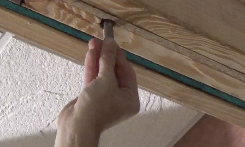
Euro-Wall Pivot Installation Guide

    Important                                               Panel Protective Film
    Before beginning the install, read the                  Remove all protective film from panels, frames
    instructions in their entirety. Perform install using   and any other metal extrusion within 30 days of
    the recommended methods contained within                job delivery. Failure to do so could cause finish
    this guide. Deviating from recommended install          damage voiding the product warranty.
    procedures could impair functionality and could
    void any warranty.
                                                            Considerations Before You Get Started
                                                            Space: Make sure there is an appropriate
    Caution                                                 amount of working space in and around the
    It is the obligation of the building owner,             install opening. It is best practice to assemble
    contractor, architect or installer to ensure that       the frame on top of saw horses (using at least
    door systems being installed comply with all            four, one for each corner), therefore, make sure
    building codes and regulations pertaining to            there is adequate room to assemble the frame
    the install location. Euro-Wall Systems, Inc.           in the area around the opening. Additionally,
    assumes no responsibility for failure to meet           leave plenty of room without clutter to maneuver
    applicable laws, ordinances, building codes, etc.       panels during install.

    Description of Supplied Parts                           Power: Ideally power should be connected
    Upon delivery please inspect for any noticeable         and accessible for tool operation and to ensure
    damage and check supplied materials with                optimal lighting conditions for the install.
    included packing list. If there is any damage and
    / or any missing components, please contact             Moving Panels: Never “walk panels” and never
    Euro-Wall as soon as possible. For installs with        try to move panels with only one person. Always
    multiple opening units, do not mix and match            lift and move panels by hand or using glass
    any components even if the units are the same           suction cups using at least two people. For
    dimensions.                                             installs less than 8’ in height, use a minimum of
                                                            two installers. For panels over 8’ tall, a team of
    Protection of Unit During Construction                  four is recommend for the install.
    It is important that during the construction
    phase the door system components are
    protected and covered in a clean dry location
    away from any factors that could cause
    damage. Door systems that are stored during
    the construction phase can often times be
    exposed to situations that can cause permanent
    damage such as cement splatter, tar, paint,weld
    spray, falling objects, construction dust,
    sandblasting, etc. After installation of the door
    system is completed and construction is still
    being performed, ensure that the large opening
    where the door system is installed does not
    become a major in and out access point for
    contractors and subcontractors. Damage
    done during the construction phase can be
    irreparable and can cause significant setbacks
    with new panels needing to be constructed.

2                                                                             2020-2021 Euro-Wall Systems, LLC • www.euro-wall.com
                                                                                       FOLDING | SLIDING | STACKING | PIVOT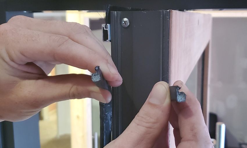
Euro-Wall Pivot Installation Guide

        A. Tools Required
        Step A.1 - Tools Checklist
        Please make sure you have all of the required tools listed below before performing the install.
         ࢚ Copy of install guide                       ࢚ SDS drill                        ࢚ Snips
         ࢚ Screw guns and chargers                     ࢚ Laser level                      ࢚ Utility knife
         ࢚ Extension bits Phillips #2 /                ࢚ Dot / plumb laser level          ࢚ Saw horses (min 4)
           #3 for tapcons                              ࢚ 2’, 4’ and 6’ levels             ࢚ Glass cups for moving
         ࢚ Drill bits for steel,                       ࢚ Pencil                             panels (min 4)
           concrete and wood                                                              ࢚ Shop-Vac
                                                       ࢚ Chalk line
         ࢚ 3/4” drill bit                                                                 ࢚ Broom / dustpan
                                                       ࢚ String line (for
         ࢚ 3/8” and 1/4” drill bits                      measuring square)                ࢚ Garbage can /
         ࢚ Hand screwdrivers                           ࢚ File                               garbage bags
           (Phillips #2 and #3)                                                           ࢚ 5mm allen key
                                                       ࢚ Pliers
         ࢚ Rubber mallet                                                                  ࢚ Protective eyeware
                                                       ࢚ Channel locks

        Step A.2 - Disposables Checklist
        Please make sure you have all of the required tools listed below before performing the install.
         ࢚ Tapcons (if drilling                        ࢚ Shims                            ࢚ Paper towels
           into concrete)                              ࢚ Backer rod                       ࢚ Cardboard / moving
         ࢚ Screws for installing frame                 ࢚ Sill pan (width of the             blankets
           into substrate (supplied)                     opening plus extra for play)     ࢚ Four 2x4’s for panel
         ࢚ Caulk / sealant                             ࢚ Windex / glass cleaner             installation
         ࢚ Lubricant / wax                             ࢚ Clean rags

        Step A.3 - Labor Checklist
        Please make sure you have the adequate number of installers
         ࢚ For installations with panels under 8 feet,                  ࢚ For installations with panels over 8 feet,
           recommended minimum of 2 installers                            recommended minimum of 4 installers

2020-2021 Euro-Wall Systems, LLC • www.euro-wall.com                                                                    3
   FOLDING | SLIDING | STACKING | PIVOT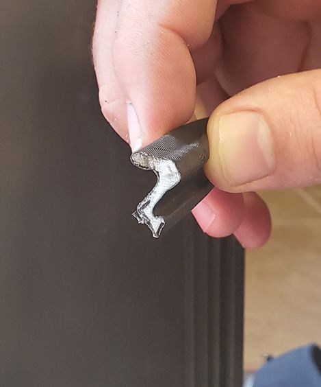
Euro-Wall Pivot Installation Guide

    B. Parts / Pieces Included
    Below you will find a summary of the parts and pieces that are included with the door system. For a
    comprehensive checklist please see the packing list included with your order.
    Step B.1 - Frame Checklist
     ࢚ Jambs (2) (See Figure B.1)
     ࢚ Header (1) (See Figure B.1)
     ࢚ Frame weatherstripping (See Figure B.2)

                                   FIGURE B.1: JAMBS & HEADER

                   Nonactive Jamb                                        Active Jamb

                        Header

    Step B.2 - Panel Checklist
    Each system comes with a designated hardware box for each panel allocated in the work order. Each
    door panel must be installed using the corresponding hardware box.

    ࢚ Panels (number designated by work order)
    ࢚ Panel weatherstripping small - see Figure B.1 to distinguish between the two different
      weatherstripping types
    ࢚ Panel weatherstripping large - see Figure B.1 to distinguish between the two different
      weatherstripping types

                     FIGURE B.2: PANEL WEATHERSTRIPPING PROFILES

                 Panel                            Panel                            Frame
         Weatherstripping Large           Weatherstripping Small               Weatherstripping
       “Large P Weatherstripping”       “Small P Weatherstripping”

4                                                                          2020-2021 Euro-Wall Systems, LLC • www.euro-wall.com
                                                                                    FOLDING | SLIDING | STACKING | PIVOT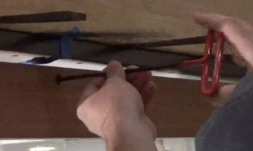
Euro-Wall Pivot Installation Guide

        Step B.3 - Hardware / Handles Checklist

                                                         NOTE:
            The hardware included with your install package will vary depending on the install configuration.
                Please check your parts packing list for the hardware specifications for this installation.

                           25N325ATF                        6C12KCSS/D912
                       Anchor Screw                          Set Screw
                   All screws for jambs and                 Quantity varies
                     header are provided

                                                                                                  DBHL-04
                                                                                             Removable Twin
                                                                                               Point Lever
                                                                                                 Quantity: 1

                              P227                            25C75MPTS
                 Shootbolt / Pivot Cups                     Frame Screw
                 Ladder Pull - Quantity: 5                  Quantity varies
               Multipoint Handle - Quantity: 3

                                                                                                62MP0500N
                                                                                             1/2” Hole Plugs
                                                                                              Quantity varies

                       C0077-A TP Socket                       NGP-673
                Modified Shootbolt Cups                     Door Sweep
            Panel w/ Ladder Pull - Quantity: 0                Quantity: 4
          Panel w/ Multipoint Handle - Quantity: 2
                                                                                                 11850-1415
                                                                                           14mm/15mm Wrench
                                                                                                 Quantity: 1

                           CP-0039-A                          CP-0038-A                      Matching Key to
                       Top Pivot Pin                      Bottom Pivot Pin                    Cylinder Lock
                          Quantity: 1                         Quantity: 1                       Quantity: 2

2020-2021 Euro-Wall Systems, LLC • www.euro-wall.com                                                             5
   FOLDING | SLIDING | STACKING | PIVOT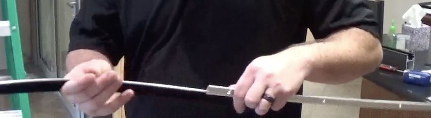
Euro-Wall Pivot Installation Guide

    C. Opening Preparation
    Step C.1 - Measure, Level, Square & Clean
    ࢚ Measure opening at at least 3 points (See    ࢚ Vacuum / sweep opening to be clear of dust /
      Figure C.1) to check for plumb, square and     dirt / debris
      level of the opening
    ࢚ Ensure that there is less than 3/16” max
      deflection at the header

                            FIGURE C1: MEASURING THE OPENING

        QR CODE: VIEW VIDEO INSTRUCTIONS ON MEASURING THE OPENING

6                                                                   2020-2021 Euro-Wall Systems, LLC • www.euro-wall.com
                                                                             FOLDING | SLIDING | STACKING | PIVOT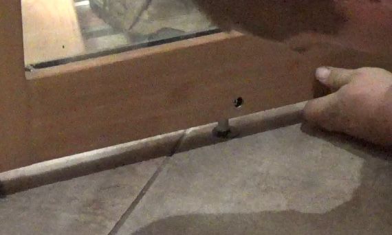
Euro-Wall Pivot Installation Guide

       Step C.2 - Swing Orientations                                Jamb Orientation

                        Right Hand
                         Outswing

                          Left Hand
                           Inswing

                          Left Hand
                          Outswing

                        Right Hand
                         Inswing

2020-2021 Euro-Wall Systems, LLC • www.euro-wall.com                                        7
   FOLDING | SLIDING | STACKING | PIVOT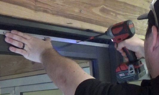
Euro-Wall Pivot Installation Guide

    D. Frame Assembly
    Step D.1 - Connect Jambs to Header
    Place the frame as it will be assembled on 4 sawhorses
    near the opening. Sawhorses should be padded /
    wrapped to protect the frame from scratches or damage.
    DO NOT ASSEMBLE FRAME ON THE GROUND. Line the
    top of the jamb edge with silicone. Turn the header and
    jamb on their sides to connect them. Install two frame
    screws (provided) on each jamb to connect to header.

    QR CODE: FRAME
    ASSEMBLY

                                                                                          Two Screw
                                                                                           Locations

    Step D.2 - Strike Plate Box                                       Strike Plate
    For the pivot door to latch into the jamb it uses a                   Box
    provided strike plate. On the back of the strike plate there
    is a strike plate box. If the strike plate is used, notch the                              Strike
    substrate that the jamb is attaching to. The strike plate
                                                                                               Plate
    box is only for aesthetics. It creates a dark cavity for the
    hook to go into and does not have to be used, as it is not
    structural.

    QR CODE: STRIKE
    PLATE BOX

    Note: The process for notching for the strike plate box
    will depend on the substrate.

    QR CODE: NOTCH
    STRIKE PLATE BOX

8                                                                   2020-2021 Euro-Wall Systems, LLC • www.euro-wall.com
                                                                             FOLDING | SLIDING | STACKING | PIVOT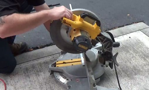
Euro-Wall Pivot Installation Guide

                                        CONFIGURATION:
                              LADDER PULL W/ A RIGHT HAND OUTSWING
                                        A-E DENOTES SHOOTBOLT CUP LOCATIONS

                               C                                   D

      Removable                                        Top Pivot        Removable
       Twinpoint                                          Pin            Twinpoint
         Lever                                                             Lever
      (Located on                                                       (Located on
     interior side)                                                    interior side)

     Ladder Pull
       Handle

     Thumb Turn
        Bolt

                                                        Bottom
                                                       Pivot Pin

                               B                          A        E

                                          (EXTERIOR VIEW)

2020-2021 Euro-Wall Systems, LLC • www.euro-wall.com                                                             9
   FOLDING | SLIDING | STACKING | PIVOT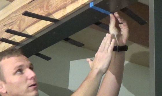
Euro-Wall Pivot Installation Guide

                                CONFIGURATION:
                      MULTIPOINT W/ A RIGHT HAND OUTSWING
                         A-E DENOTES SHOOTBOLT CUP LOCATIONS

                  C                              D                                                                           C

                                     Top Pivot        Removable                                  Removable
                                        Pin            Twinpoint                                  Twinpoint
                                                         Lever                                      Lever
                                                      (Located on                                (Located on
                                                     interior side)                             interior side)

                                                                                                Ladder Pull
                                                                                                  Handle
     Multipoint
      Handle
                                                                                                Thumb Turn
                                                                                                   Bolt

                                      Bottom
                                     Pivot Pin

                  B                        A     E                                                                           B

                          (EXTERIOR VIEW)

10                                                                    2020-2021 Euro-Wall Systems, LLC • www.euro-wall.com
                                                                               FOLDING | SLIDING | STACKING | PIVOT
Euro-Wall Pivot Installation Guide
E. Dry Fit Frame Move Frame
Into Opening
Step E.1 - Mark Top Pivot Pin Location
Move the frame into the opening. Check the jambs and
header to make sure they are plumb, square and level.
Reveal should be equal on both sides of the header. Mark
the top pivot pin location. Remove frame from opening.
QR CODE: DRY FIT
FRAME & MARK TOP
PIVOT PIN LOCATION Mark
Top Pivot
Note: The video refers to dry fitting the frame next to a
Location
transom, however if the configuration doesn’t have a
transom these steps are the same with any substrate.
F. Drill Top Pivot Pin Location Drill Top
Pivot Pin
Step F.1 - Drill Top Pivot Pin Location Location
With any drilling done, make sure the appropriate PPE is
used. Start by predrilling the top pivot pin location with
a 3/16” bit. Then move up to using a 1” bit. The type of
bit that used is dependant upon the substrate. (If the
substrate is wood, use a 1” wood bit. If the substrate is
steel, use a 1” steel bit. If the substrate is concrete, use
a 1” SDS bit.) After the 1” hole is drilled, verify that the
top pivot pin fits all the way flush into the hole. When
the panel is moved into the opening, the pivot pin will be Verify Top
Pivot Pin
installed in the header and will need to be pushed up into Fits Flush
this hole. With The
Drilled Hole
QR CODE: DRILL TOP
PIVOT PIN LOCATION
2020-2021 Euro-Wall Systems, LLC • www.euro-wall.com 11
FOLDING | SLIDING | STACKING | PIVOTEuro-Wall Pivot Installation Guide
G. Install Frame
Place Top
Step G.1 - Install Top Pivot Pin Pivot Pin In
Frame
Place the top pivot pin into the header. Move the frame
into the opening. Once the frame is in the correct spot,
the pivot pin should easily push up into the drilled hole.
QR CODE: INSTALL
TOP PIVOT PIN
Step G.2 - Attach Frame to Opening
Square, level and plumb the frame to the substrate.
Predrill in all the locations (for all substrate conditions)
along the jambs and header using a 3/16” drill bit. Install
1/4” screws (supplied) in all the predrilled locations, Predrill All
connecting the pivot jambs and header to the substrate. Locations
QR CODE: ATTACH
FRAME TO OPENING
Note: The video refers to attaching the frame to a
transom, however if the configuration doesn’t have a
transom these steps are the same with any substrate.
12 2020-2021 Euro-Wall Systems, LLC • www.euro-wall.com
FOLDING | SLIDING | STACKING | PIVOTEuro-Wall Pivot Installation Guide
H. Install Pivot Pin Cup A
Use Laser
Step H.1 - Mark Pivot Pin Cup A Location Level To Mark
Pivot Pin Cup
Make sure the top pivot pin is hanging straight down. A Location
Plumb using a dot/plumb laser level, mark the bottom
pivot pin location using the top pivot bolt as the reference
point. Take a 3/4” bit and place it on the ground where
the laser is pointing to. Trace around the bit with a pencil
to mark the drill location for pivot cup A.
QR CODE:
MARK PIVOT
PIN CUP A
LOCATION Trace Bit
To Mark
Location To
Drill
Exterior View
Step H.2 - Drill Pivot Pin Cup A Location
Using a 3/4” drill bit, drill out the bottom pivot pin cup
A location to a depth of 1-1/4”. The type of 3/4” drill bit
used is dependent on the substrate.
Drill Pivot
QR CODE: DRILL PIVOT PIN Pin Cup A
CUP A LOCATION Location
Step H.3 - Install Pivot Pin Cup A
Check to verify that the pivot cup sits flush into the drilled
hole. Predrill out pivot pin cup A location with a 3/16”
SDS. Secure pivot pin cup A with 1/4” tapcon screw.
Predrill
QR CODE: INSTALL BOTTOM Pivot Pin
PIVOT PIN CUP A Cup A
2020-2021 Euro-Wall Systems, LLC • www.euro-wall.com 13
FOLDING | SLIDING | STACKING | PIVOTEuro-Wall Pivot Installation Guide
I. Install Panel Tape Top Pivot
Pin Up Into
Step I.1 - Secure Top Pivot Pin Drilled Hole
Before placing the panel in the opening, use blue tape to
push the top pivot pin up into the header to keep it out of
the way as the panel is installed.
QR CODE: SECURE TOP
PIVOT PIN
Step I.2 - Preparation for Panel Install
Place 2x4’s In
Place 2x4’s or other wood that is at least 1-1/2” thick by
Opening For
the opening for the panel to rest on. The bottom pivot Panel To Rest On
pin sticks out a little over 1”. The bottom pivot pin should
never make contact with the ground; this could damage
the pin and/or the panel.
QR CODE: PREPARATION
FOR PANEL INSTALL
Step I.3 - Move Panel Onto Wood
Use a minimum of 4 people to move the panel onto the
pieces of wood. Do not let the bottom pivot pin come in
contact with the ground. Once in place, push the panel
into the upright position.
Move Panel
QR CODE: MOVE PANEL Onto Wood
ONTO WOOD
14 2020-2021 Euro-Wall Systems, LLC • www.euro-wall.com
FOLDING | SLIDING | STACKING | PIVOTEuro-Wall Pivot Installation Guide
Step I.4 - Insert Bottom Pivot Pin
Attach glass cups onto the panel. Lift panel up and guide
the bottom pivot pin into the bottom pivot pin cup.
QR CODE: INSERT BOTTOM Insert Bottom
PIVOT PIN INTO LOCATION A Pivot Pin
Step I.5 - Shim the Panel
Shim the bottom of the panel so you have equal gapping
between the panel - header and the panel - floor. Make
sure the top pivot is aligned with the pivot location on
the panel.
Shim The
Panel
QR CODE: SHIM THE PANEL
Step I.6 - Securing the Panel
Remove the 5mm allen set screw on the interior of the top Set Screw
rail and remove the blue tape covering the top pivot pin. Location
The top pivot pin should fall into place into the top rail.
Use a double ended 14mm/15mm wrench to thread top
pivot pin into panel. Use the 15mm end of the wrench for
the first half of threading the pivot pin. Use the 14mm end
of the wrench for threading the second half of the pivot
pin. (See Figure I.6) Continue to thread until there is an
even 3/8” gap at the top and bottom of the panel. Use the
allen key to secure/tighten the 5mm allen set screw into
the panel on the flat side of top pivot pin.
QR CODE: FIGURE I.6
SECURING
THE PANEL
Thread Pivot
Pin Into Panel
14mm
wrench
15mm
wrench
2020-2021 Euro-Wall Systems, LLC • www.euro-wall.com 15
FOLDING | SLIDING | STACKING | PIVOTEuro-Wall Pivot Installation Guide
Step I.7 - Test Opening Panel Test Opening
Test operation by slowly opening the panel to make sure The Panel
there’s no rubbing issues on any side of the panel.
QR CODE: TEST OPENING
PANEL
J. Frame Weatherstripping
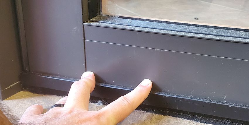
Step J.1 - Install Frame Weatherstripping
Install frame weatherstripping on the jamb with the riser.
The door needs to have the correct spacing before
installing the bottom shootbolt cup. The weatherstripping
pushes into the groove all the way down the jamb. Install Frame
Weatherstripping
QR CODE: INSTALL FRAME
WEATHERSTRIPPING
K. Install Shootbolt Cup B
Step K.1 - Mark Shootbolt Cup B Location
(See Figure E.1) Place several layers of blue tape on the
flooring substrate at the shootbolt B location. Close the
door, compress it against the jamb and make sure the
latch from the thumb bolt/multipoint handle (See Figure Place Blue Tape
K.1) lines up with strike plate. Lock and unlock the door On Flooring
several times to engage the shootbolt leaving an indent in
the blue tape, marking the spot for the shootbolt B cup.
QR CODE:
MARK
SHOOTBOLT
CUP B
LOCATION
Engage Lock To Mark
Shootbolt Cup B Location
Exterior View
16 2020-2021 Euro-Wall Systems, LLC • www.euro-wall.com
FOLDING | SLIDING | STACKING | PIVOTEuro-Wall Pivot Installation Guide
FIGURED K.1: MULTIPOINT HANDLE OPERATION INSTRUCTIONS
Unlock: To unlock and open, turn the thumb bolt (if applicable) to the unlock position until it cannot
rotate any further and turn the handle fully down - this will disengage the multipoint lock, allowing the
door to open.
Lock: Prior to engaging the thumb bolt (if applicable), turn the handle up roughly 45° (see illustration
below) to engage the locking points. After the locking mechanism is engaged, release the handle and
let it move back down to the normal position. Lock the thumb bolt lock by rotating it until locked and
cannot rotate any further (if applicable).
Normal Position Unlocking Engaging / Locking
QR CODE: MULTIPOINT
HANDLE OPERATION
Step K.2 - Drill Shootbolt Cup B Location
Drill out the shootbolt cup B location where the blue tape
is indented using a 3/4” appropriate substrate bit.
Drill
Shootbolt
Cup B
Location
2020-2021 Euro-Wall Systems, LLC • www.euro-wall.com 17
FOLDING | SLIDING | STACKING | PIVOTEuro-Wall Pivot Installation Guide
Step K.3 - Install Shootbolt Cup B
Insert the shootbolt cup into the drilled hole. Drill out
the shootbolt cup B with 3/16” SDS and anchor in place
using a 1/4” tapcon screw.
Install
Shootbolt
Cup B
Shootbolt / Pivot Cup Modified Shootbolt Cup
This cup will be used for cups B & C if This cup will be used for cups B & C if
your door has a ladder pull handle. your door has a multipoint handle.
Step K.4 - Test Shootbolt Cup B
Close the door and turn the thumb bolt lock or multipoint
handle lock to engage the shootbolt. Test to ensure the
shootbolt goes into shootbolt cup B.
Test
Shootbolt
QR CODE: TEST
SHOOTBOLT CUP B
18 2020-2021 Euro-Wall Systems, LLC • www.euro-wall.com
FOLDING | SLIDING | STACKING | PIVOTEuro-Wall Pivot Installation Guide
L. Panel Weatherstripping
Step L.1 - Install Panel Weatherstripping
There will be two types of panel weatherstripping that
are different sizes. Choose the appropriate size panel
weatherstripping based on the gap around the frame. If
there is an 1/8” gap use “small p”, if there is a 1/4” gap Install Panel
use “large p”. When the door closes the weatherstripping Weatherstripping
should compress securely. The weatherstripping pushes
into the grove along the jamb.
Panel
Weatherstripping
Panel Panel
Weatherstripping Large Weatherstripping Small
“Large P Weatherstripping” “Small P Weatherstripping”
QR CODE: INSTALL PANEL
WEATHERSTRIPPING
M. Install Shootbolt Cup C Place Several
Layers Of Blue
Step M.1 - Mark Shootbolt Cup C Location Tape
(See Figure E.1) Place several layer of blue tape on the
shootbolt cup C location. If your door has a ladder pull
handle, engage the removable twinpoint lever several
times to make indents in the blue tape, marking the
shootbolt cup C location. Insert the removable twinpoint
lever horizontally then turn it to engage it. (See Step P) If
your door has a multipoint handle, engage the the handle
several times to make indents in the blue tape, marking
the shootbolt cup C location. (See Figure K.1)
QR CODE: Engage Shootbolt To Mark
MARK Shootbolt Cup C Location
SHOOTBOLT
CUP C
LOCATION
Exterior View
2020-2021 Euro-Wall Systems, LLC • www.euro-wall.com 19
FOLDING | SLIDING | STACKING | PIVOTEuro-Wall Pivot Installation Guide
Step M.2 - Drill Shootbolt Cup C Location
Drill out the shootbolt cup C location where the blue tape
is indented. Start using a 1/4” bit, then a 1/2” bit and
work up to using a 3/4” steel bit. Use an appropriate bit
for the substrate for the rest of the header.
Drill Shootbolt
Cup C Location
Step M.3 - Install Shootbolt Cup C
Insert the shootbolt cup into the drilled hole. Use the
appropriate screw for the substrate. If drilling into
concrete, predrill the shootbolt cup 1/4” to accommodate
the tapcon. Drill out the shootbolt cup C with 3/16” SDS
and screw in a 1/4” tapcon screw.
Install
Shootbolt Cup C
Step M.4 - Test Shootbolt Cup C
Close the door and test to make sure the shootbolt goes
into the shootbolt cup C.
Test Shootbolt
20 2020-2021 Euro-Wall Systems, LLC • www.euro-wall.com
FOLDING | SLIDING | STACKING | PIVOTEuro-Wall Pivot Installation Guide
N. Install Shootbolt Cup D Install
Shootbolt
Step N.1 - Mark, Drill & Install Shootbolt Cup D Cup D
(See Figure E.1) Repeat steps M.1-M.4 for the
installation of shootbolt cup D. Insert and engage the
removable twinpint lever to make the indents on the blue
tape. Insert the removable twinpoint lever horizontally
then turn it 90° clockwise to engage it. (See Step P)
QR CODE:
INSTALL
SHOOTBOLT
CUP D
Exterior View
O. Install Shootbolt Cup E
Step O.1 - Mark, Drill & Install Shootbolt Cup E
(See Figure E.1) Repeat steps K.1-K.4 for the installation
of shootbolt cup E. Insert and engage the removable
twinpint lever to make the indents on the blue tape. Insert Install
Shootbolt
the removable twinpoint lever horizontally then turn it 90° Cup E
clockwise to engage it. (See Step P)
QR CODE:
INSTALL
SHOOTBOLT
CUP E
Exterior View
2020-2021 Euro-Wall Systems, LLC • www.euro-wall.com 21
FOLDING | SLIDING | STACKING | PIVOTEuro-Wall Pivot Installation Guide
P. Removable Twinpoint
Lever
Step P.1 - Removable Twinpoint Lever Usage
Twinpoint levers are used during inclement weather and
offer the security of a top and bottom locking shootbolt. Twinpoint
Lever
Remove the two plugs on the interior side of the panel Location
located near the top of the stiles. To engage and lock
the twinpoints make sure the lever is turned completely
down into the locked position. The configuration will
determine which direction the twinpoint lever must turn
to unlock. To disengage and unlock the twinpoint turn the
lever roughly 90°, towards the center of the panel.
Engage
QR CODE: REMOVABLE Twinpoint
TWINPOINT LEVER Lever
Unlocked Position Unlocked Position Locked Position
22 2020-2021 Euro-Wall Systems, LLC • www.euro-wall.com
FOLDING | SLIDING | STACKING | PIVOTEuro-Wall Pivot Installation Guide
Q. Sweeps
Step Q.1 - Prepare Sweeps for Install
Make sure the door is closed and locked when
measuring for sweep installation. Measure from the gaps
between the panel and frame to calculate the length of
Measure Length
the sweeps. Remove the brushes from the sweeps, use
For Sweeps
a chop saw to cut the sweeps down to the appropriate
size. Use tin snips to cut the brush. Reinsert the brush
back into the sweep.
QR CODE: PREPARE
SWEEPS FOR INSTALL
Remove Brush From Sweeps Cut
Sweeps To
Measured
Length
Step Q.2 - Install Sweeps
Drill Holes For
Check to make sure the sweeps are cut to the correct Sweeps
size. Place sweeps against the panel and position to
where the sweep is slightly compressed. Predrill through
the provided holes of the sweeps or at the locations
chosen. Cut the sweep cover down to the appropriate
size. Then attach the sweep cover by tapping along the
whole sweep with a rubber mallet. Repeat these steps to
install the exterior bottom and interior sweeps.
Due to the Panel
Construction You Cannot Install Sweep
Drill Within the First 4” Cover
of the Bottom Rail
QR CODE:
INSTALL SWEEPS
2020-2021 Euro-Wall Systems, LLC • www.euro-wall.com 23
FOLDING | SLIDING | STACKING | PIVOTEuro-Wall Pivot Installation Guide
R. Water Drainage System
Step R.1 - Drain Installation
Install drain on interior of the panel location making sure to align the center of the drainage channel to
the inside edge of the panel. Ensure there are no kinks in the drain tube to allow for clear flow of water
drainage. Make sure drainage tube flows to an adequate location away from the door location. In
certain cases additional drainage tube may be needed based upon the drain location.
FIGURE R.1
Exterior
Interior
Check Valve
Step R.2 - Secure Channel
Secure the channel with the appropriate anchors for your substrate and allow for tile (or other floor
covering) to cover the channel while leaving a 1/4” gap to allow the water to pass into the drainage
system. Seal all screw penetrations and end of the channel with sealant.
Step R.3 - Test Drainage System
Test drainage system to verify there are no leaks.
24 2020-2021 Euro-Wall Systems, LLC • www.euro-wall.com
FOLDING | SLIDING | STACKING | PIVOTEuro-Wall Pivot Installation Guide
S. Maintenance & Care
Panel Protective Film Hangers, Pivots and Brackets
Remove all protective film from panels, frames Before applying anti-corrosive substance, wipe
and any other metal extrusion within 30 days of exposed surfaces with clean soft cloth soaked
job delivery. Failure to do so could cause finish in warm soapy water; then rinse, clean and dry.
damage voiding the product warranty. Spray thin film to hangers, pivots and brackets
with anti-corrosive substance, such as, CRC
Marine 66®, Innox® or CorrosionX®.
Hinges
Wipe down the visible surfaces with warm soapy
water on a soft cloth and then rinse off by wiping Frequency
with a clean damp cloth. Regular maintenance is required for all hardware,
even stainless steel, to keep manufacturer’s
warranty in place. Failure to provide proof of
Locks and Hardware
maintenance will void any warranty.
Wipe down the visible surfaces with warm soapy
water on a soft cloth and then rinse off by wiping Carry out maintenance procedures with the
with a clean damp cloth. Spray a thin film of light following minimum recommendations:
machine oil or one of the corrosion preventative • General environments - every 3 months
sprays such as CRC Marine 66®, Innox® or
• Marine, industrial environments, within 5
CorrisionX®. Be careful to avoid getting these
miles of a body of water and / or a pool area -
compounds on wood or fiberglass panels or
every month.
jambs as they may cause staining. Be sure to
wipe down any overspray.
Inclement Weather
Twinpoint levers are used during inclement
Track and Bearings weather and offer the security of a top and
Apply white petroleum jelly (Vaseline) or bottom locking shootbolt. Remove the two
equivalent, to inner lip of each side of head plugs on the interior side of the panel located
track with a clean cloth. Distribute lubricant near the top of the stiles. To engage and lock
evenly along track. Ensure wheels and bearings the twinpoints make sure the lever is turned
receive sufficient lubricant. Wipe all contaminant completely down into the locked position. The
from track surfaces with damp cloth and mild configuration will determine which direction the
detergent, clean surfaces with clean soft cloth. twinpoint lever must turn to unlock. To disengage
Apply thin film for systems installed in severe and unlock the twinpoint turn the lever roughly
environments by wiping surfaces of track with 90°, towards the center of the panel.
anti-corrosive substance, such as, CRC Marine
66®, Innox® or CorrosionX®.
QR CODE: REMOVABLE
TWINPOINT LEVER
NOTE: Maintenance is required to extend the life of
your door system and to maintain the Euro-Wall Warranty
2020-2021 Euro-Wall Systems, LLC • www.euro-wall.com 25
FOLDING | SLIDING | STACKING | PIVOTYou can also read