SIDLuxe - SERVICE MANUAL - SRAM
←
→
Page content transcription
If your browser does not render page correctly, please read the page content below
SIDLuxe

SERVICE MANUAL

                 GEN.0000000006221 Rev B © 2020 SRAM, LLC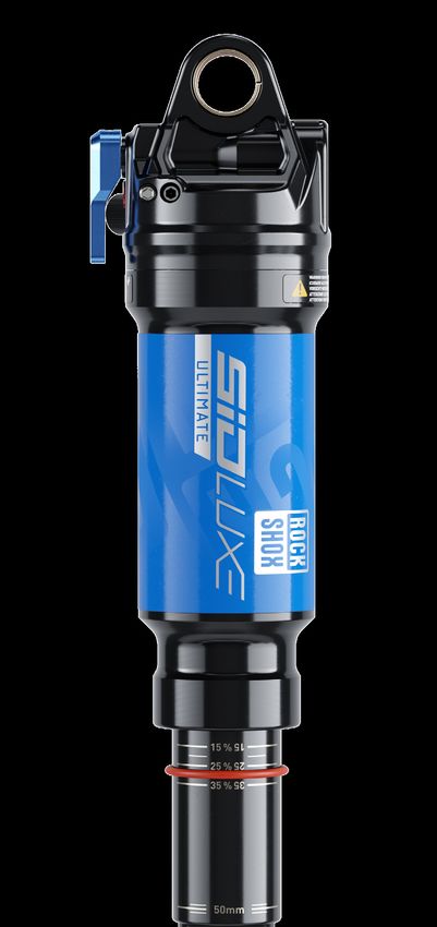
SRAM® LLC WARRANTY
THIS WARRANTY GIVES YOU SPECIFIC LEGAL RIGHTS AGAINST SRAM, LLC. YOU MAY ALSO HAVE OTHER RIGHTS THAT VARY FROM
STATE TO STATE, COUNTRY, OR PROVINCE. THIS WARRANTY DOES NOT AFFECT YOUR STATUTORY RIGHTS. TO THE EXTENT THIS
WARRANTY IS INCONSISTENT WITH THE LOCAL LAW, THIS WARRANTY SHALL BE DEEMED MODIFIED TO BE CONSISTENT WITH SUCH
LAW. FOR A FULL UNDERSTANDING OF YOUR RIGHTS, CONSULT THE LAWS OF YOUR COUNTRY, PROVINCE, OR STATE.
EXTENT OF LIMITED WARRANTY
Except as otherwise set forth herein, SRAM warrants its bicycle components to be free from defects in materials or workmanship for a period of two
(2) years after original purchase of the product.
SRAM warrants all Zipp MOTO Wheels and Rims to be free from defects in materials or workmanship for the lifetime of the product.
SRAM warrants all non-electronic Zipp branded bicycle components, Model Year 2021 or newer, to be free from defects in materials or workmanship
for the lifetime of the product.
GENERAL PROVISIONS
This warranty only applies to the original owner and is not transferable. Claims under this warranty must be made through the retailer where the
bicycle or the SRAM product was purchased or a SRAM authorized service location. Original proof of purchase is required. All SRAM warranty claims
will be evaluated by a SRAM authorized service location whereupon acceptance of the claim the product will be repaired, replaced, or refunded at
SRAM's discretion. To the extent allowed by local law claims under this warranty must be made during the warranty period and within one (1) year
following the date on which any such claim arises.
NO OTHER WARRANTIES
EXCEPT AS DESCRIBED HEREIN, AND TO THE EXTENT ALLOWED BY LOCAL LAW, SRAM MAKES NO OTHER WARRANTIES, GUARANTIES, OR
REPRESENTATIONS OF ANY TYPE (EXPRESS OR IMPLIED), AND ALL WARRANTIES (INCLUDING ANY IMPLIED WARRANTIES OF REASONABLE
CARE, MERCHANTABILITY, OR FITNESS FOR A PARTICULAR PURPOSE) ARE HEREBY DISCLAIMED.
LIMITATIONS OF LIABILITY
EXCEPT AS DESCRIBED HEREIN, AND TO THE EXTENT PERMITTED BY LAW, IN NO EVENT SHALL SRAM OR ITS THIRD PARTY SUPPLIERS BE
LIABLE FOR DIRECT, INDIRECT, SPECIAL, INCIDENTAL, OR CONSEQUENTIAL DAMAGES. SOME STATES (COUNTRIES AND PROVINCES) DO NOT
ALLOW THE EXCLUSION OR LIMITATION OF INCIDENTAL DAMAGES, SO THE ABOVE LIMITATION MAY NOT APPLY TO YOU.
LIMITATIONS OF WARRANTY
This warranty does not apply to products that have been incorrectly installed, adjusted, and/or maintained according to the respective SRAM user
manual. The SRAM user manuals can be found online at sram.com/service.
This warranty does not apply to damage to the product caused by a crash, impact, abuse of the product, non-compliance with manufacturer's
specifications of intended usage, or any other circumstances in which the product has been subjected to forces or loads beyond its design.
This warranty does not apply when the product has been modified, including but not limited to, any attempt to open or repair any electronic and
electronic related components, including the motor, controller, battery packs, wiring harnesses, switches, and chargers.
This warranty does not apply when the serial number or production code has been deliberately altered, defaced, or removed.
SRAM components are designed for use only on bicycles that are pedal powered or pedal assisted (e-Bike/Pedelec).
Notwithstanding anything else set forth herein, the battery pack and charger warranty does not include damage from power surges, use of improper
charger, improper maintenance, or such other misuse.
This warranty shall not cover damages caused by the use of parts of different manufacturers or parts that are not compatible or suitable for use with
SRAM components.
This warranty shall not cover damages resulting from commercial (rental) use.
WEAR AND TEAR
This warranty does not apply to normal wear and tear. Wear and tear parts are subject to damage as a result of normal use, failure to service
according to SRAM recommendations, and/or riding or installation in conditions or applications other than recommended.
WEAR AND TEAR PARTS INCLUDE:
• Aero bar pads            • Chains                                        • Rear shock mounting                 • Stripped threads/bolts (aluminum,
• Air sealing o-rings      • Corrosion                                       hardware and main seals               titanium, magnesium or steel)
• Batteries                • Disc brake rotors                             • Rubber moving parts                 • Tires
• Bearings                 • Dust seals                                    • Shifter and Brake cables            • Tools
• Bottomout pads           • Free hubs, Driver bodies, Pawls                 (inner and outer)                   • Transmission gears
• Brake pads               • Foam rings, Glide rings                       • Shifter grips                       • Upper tubes (stanchions)
• Bushings                 • Handlebar grips                               • Spokes                              • Wheel braking surfaces
• Cassettes                • Jockey wheels                                 • Sprockets

ZIPP IMPACT REPLACEMENT POLICY
Zipp branded products, Model Year 2021 or newer, are covered under a lifetime impact-damage replacement policy. This policy can be used to obtain
a replacement of a product in the event of non-warranty impact damage occurring while riding your bicycle. See www.zipp.com/support for more
information.
SAFETY FIRST!
We care about YOU. Please, always wear your safety glasses
and protective gloves when servicing RockShox® products.
          Protect yourself! Wear your safety gear!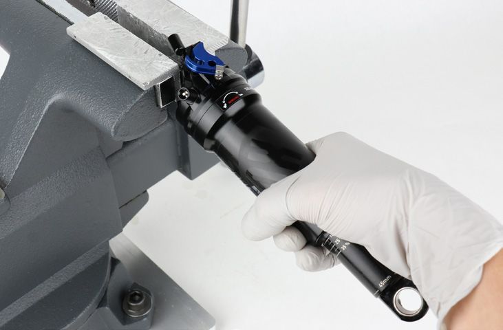
TABLE OF CONTENTS
ROCKSHOX SERVICE...........................................................................................................................................................................................5
       PART PREPARATION .......................................................................................................................................................................................................................................5
       SERVICE PROCEDURES..................................................................................................................................................................................................................................5
       PARTS, TOOLS, AND SUPPLIES...................................................................................................................................................................................................................6
       RECOMMENDED SERVICE INTERVALS..................................................................................................................................................................................................... 7
       RECORD YOUR SETTINGS............................................................................................................................................................................................................................. 7
       TORQUE VALUES.............................................................................................................................................................................................................................................. 7

EXPLODED VIEW - SIDLUXE...............................................................................................................................................................................8

EXPLODED VIEW - REMOTE OPTIONS.............................................................................................................................................................9

REMOTE CABLE AND HOUSING REMOVAL - REMOTE ONLY....................................................................................................................10
       PARTS, TOOLS, AND SUPPLIES.................................................................................................................................................................................................................10
       REMOTE CABLE AND HOUSING REMOVAL.......................................................................................................................................................................................... 10

SHOCK EYELET SERVICE...................................................................................................................................................................................11
       MOUNTING HARDWARE AND BUSHING SERVICE.............................................................................................................................................................................. 11
       PARTS, TOOLS, AND SUPPLIES.................................................................................................................................................................................................................. 11
       MOUNTING HARDWARE REMOVAL.......................................................................................................................................................................................................... 11
       EYELET BUSHING REMOVAL...................................................................................................................................................................................................................... 14

SIDLUXE SERVICE..............................................................................................................................................................................................15
       PARTS, TOOLS AND SUPPLIES.................................................................................................................................................................................................................. 15
                                                                                                         50/200 HOUR SERVICE
       AIR CAN REMOVAL........................................................................................................................................................................................................................................ 16
       BOTTOMLESS TUNING................................................................................................................................................................................................................................. 18
       AIR CAN SERVICE........................................................................................................................................................................................................................................... 19
                                                                                                            200 HOUR SERVICE
       DAMPER BODY SERVICE............................................................................................................................................................................................................................. 22
       PISTON SERVICE............................................................................................................................................................................................................................................ 24
       IFP AND DAMPER BODY SERVICE............................................................................................................................................................................................................ 31
       SHOCK ASSEMBLY AND BLEED .............................................................................................................................................................................................................. 33
                                                                                                         50/200 HOUR SERVICE
       AIR CAN INSTALLATION.............................................................................................................................................................................................................................. 36

SHOCK EYELET ASSEMBLY............................................................................................................................................................................. 38
       EYELET BUSHING INSTALLATION........................................................................................................................................................................................................... 38
       MOUNTING HARDWARE INSTALLATION............................................................................................................................................................................................... 39

REMOTE CABLE AND HOUSING INSTALLATION - REMOTE....................................................................................................................... 41
       PARTS, TOOLS, AND SUPPLIES................................................................................................................................................................................................................. 41
       REMOTE CABLE AND HOUSING INSTALLATION................................................................................................................................................................................. 41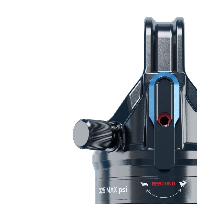
RockShox Service
We recommend that you have your RockShox suspension serviced by a qualified bicycle mechanic. Servicing RockShox suspension requires
knowledge of suspension components, as well as the use of specialized tools and lubricants/fluids. Failure to follow the procedures outlined in this
service manual may cause damage to your component and void the warranty.
Visit www.sram.com/service for the latest RockShox Spare Parts catalog and technical information. For order information, please contact your local
SRAM distributor or dealer.
Information contained in this publication is subject to change at any time without prior notice.
Your product's appearance may differ from the pictures contained in this publication.
      For recycling and environmental compliance information, please visit https://www.sram.com/en/company/about/environmental-policy-and-recycling.

 Part Preparation
Remove the component from the bicycle before service.
Disconnect and remove the remote cable or hydraulic hose from the fork or rear shock, if applicable. Instructions to remove the remote cable and
housing can be found in the Remote Cable and Housing Removal section. For additional information about RockShox remotes, user manuals are
available at www.sram.com/service.
Clean the exterior of the product with mild soap and water to avoid contamination of internal sealing part surfaces.

 Service Procedures
The following procedures should be performed throughout service, unless otherwise specified.

Clean the part with RockShox Suspension Cleaner or isopropyl alcohol and a
clean, lint-free shop towel.
Clean the sealing surface on the part and inspect it for scratches.

Replace the o-ring or seal with a new one from the service kit. Use your
fingers or a pick to pierce and remove the old seal or o-ring.
Apply RockShox Dynamic Seal Grease to the new seal or o-ring. If a brush is
used to apply grease, confirm there are no loose bristles in the grease or on
the part.

                                     NOTICE
 Do not scratch any sealing surfaces when servicing the product. Scratches
 can cause leaks. Consult the spare parts catalog to replace the damaged
 part.

To prevent damage to the shock, use aluminum soft jaws and position the
eyelet in the vise so that the adjustment knobs and/or remote cable stops are
clear of the vise jaws. For bearing mount shocks, wrap a shop towel around
the eyelet, then clamp the eyelet flat into the vise.
Tighten the part with a torque wrench to the torque value listed in the red bar.
When using a crowfoot socket and torque wrench, install the crowfoot socket
at 90 degrees to the torque wrench.

                                                                                                                        Specified torque value in N·m (in-lb)

                                                                                                                                RockShox Service                5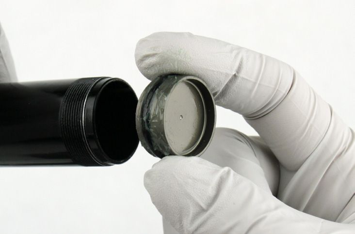
P a r t s , To o l s , a n d S u p p l i e s
Parts                                                                  RockShox Tools
• RockShox SIDLuxe 50 or 200 Hour Service Kit                          • RockShox 1/2" x 1/2" rear shock bushing removal/installation tool
Safety and Protection Supplies                                         • RockShox SIDLuxe Air Valve Adapter Tool
• Apron                                                                • SIDLuxe IFP Height Tool
• Clean, lint-free shop towels                                         • SIDLuxe Body Vise Block
• Nitrile gloves                                                       Common Tools
• Oil pan                                                              • Adjustable wrench
• Safety glasses                                                       • Bench vise with aluminium soft jaws
Lubricants and Fluids                                                  • Cable and housing cutters
• Maxima PLUSH 7wt Suspension Oil                                      • Cone wrench: 18 mm
• Maxima Extra 15w50 Suspension Oil                                    • Crowfoot socket wrenches: 13 mm, 18 mm, 19 mm
• RockShox Suspension Cleaner or Isopropyl alcohol                     • Flat blade screwdriver
• RockShox Dynamic Seal Grease                                         • Hex wrenches: 2 mm, 2.5 mm, 5 mm
Bicycle Tools                                                          • Hex bit sockets: 2 mm, 5 mm
• Schrader valve core tool                                             • Open end wrenches: (2) 13 mm, 19 mm
• High Pressure Shock Pump 600 psi                                     • Pick
                                                                       • Strap wrench
                                                                       • Torque wrench

                                                      SAFETY INSTRUCTIONS
Always wear safety glasses and nitrile gloves when working with suspension oil.
Place an oil pan on the floor underneath the area where you will be working on the shock or suspension fork.

                                                                                                                   Parts, Tools, and Supplies   6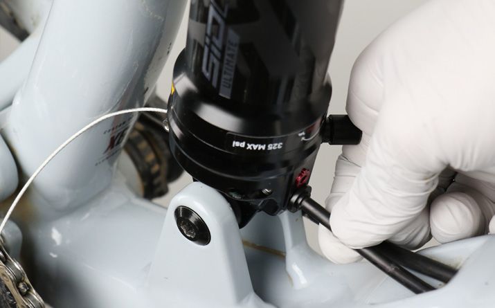
Recommended Service Intervals
Regular service is required to keep your RockShox product working at peak performance. Follow this maintenance schedule and install the service
parts included in each service kit that corresponds with the Service Hours Interval recommendation below. For spare part kit contents and details,
refer to the RockShox Spare Parts Catalog at www.sram.com/service.

 Service Hours Interval          Maintenance                                    Benefit

                                                                                Extends wiper seal lifespan
                                 Clean dirt from shock damper body and
 Every ride                                                                     Minimizes damage to shock damper body
                                 wiper seal
                                                                                Minimizes air can contamination

                                                                                Reduces friction
 Every 50 Hours                  Perform air can service
                                                                                Restores small bump sensitivity

                                                                                Extends suspension lifespan
 Every 200 Hours                 Perform damper and spring service
                                                                                Restores suspension performance

 R e c o r d Yo u r S e t t i n g s
Use the charts below to record your shock settings to return your shock to its pre-service settings. Record your service date to track
service intervals.

                                                                                                                  Rebound setting - Count the
                                                                                                                  number of clicks while turning the
 Service Hours Interval          Date of Service                         Air Pressure
                                                                                                                  rebound adjuster fully
                                                                                                                  counter-clockwise.

 50

 100

 150

 200

 To r q u e Va l u e s
 Part                                                                           Tool                                  Torque
 SIDLuxe Bottomless Token                                                       2 mm hex                              0.68 N•m (6 in-lb)
 Piston bolt                                                                    18 mm cone wrench/crowfoot            4.5 N•m (40 in-lb)
 Spool cup                                                                      19 mm, 5 mm hex                       2.8 N·m (25 in-lb)
 Seal head/air piston                                                           19 mm crowfoot                        28 N•m (248 in-lb)
 Air can                                                                        13 mm crowfoot, strap wrench          4.5 N•m (40 in-lb)
 Cable set screw                                                                2 mm hex                              0.9 N•m (8 in-lb)

                                                                                                                  Recommended Service Intervals        7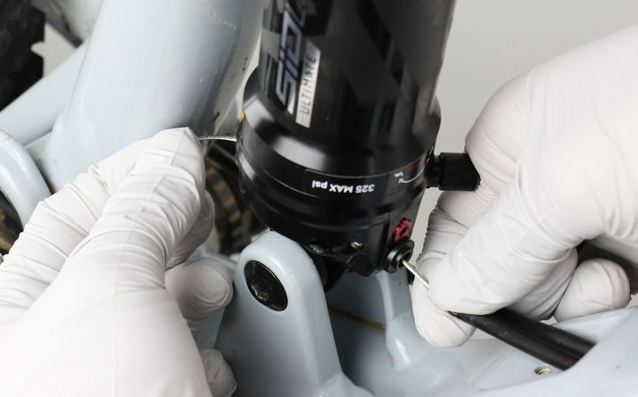
Exploded View - SIDLuxe

 RL

                                 Shaft eyelet

                                 Rebound adjuster
                                 Lockout lever
                                 Air valve
                                                                                                             Travel spacer
                                 Volume equalizer - Standard eyelet only
                                 (Do not remove)
                                                                                                                 Set screw
                                 Bottom out washer
                                                                                                                 Bottomless Token
                                 Bottom out bumper

                                 Bleed screw and
                                 compression ball
                                 Seal head / air piston

                                 Thick glide ring
                                 Quad ring seal                             Air Can
                                 Thin glide ring

                                 Open piston
                                 Main piston assembly

                                 Piston bolt

                                 Valve spool

                   Valve cup
                                                                           Air can
                  Piston cup

IFP (Internal Floating Piston)

                                                                                       Quad seal

                                                    Damper body                       Backup ring

                                                                                       Wiper seal

                                                                              Sag indicator o-ring

                                                           Damper air/nitrogen fill port

                                                           Damper body eyelet

                                                                                                     Exploded View - SIDLuxe    8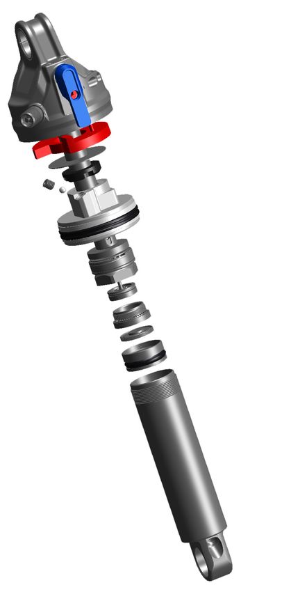
Exploded View - Remote Options

Remote: Out
Shocks that route the cable away from the shock are called "out" shocks.

                                                                  Remote cable stop

                                                                  Lockout pulley

                                                                  Rebound adjuster

                                                                  Cable set screw

Remote: In
Shocks that route the cable toward the shock are called "in" shocks.

                                                                Cable set screw

                                                                Lockout pulley
                                                                Remote cable stop
                                                                Rebound adjuster

Remote: 90˚˚
Shocks that route the cable through the eyelet are called "90˚˚ " shocks.

         Cable set screw

                                                                 Remote cable stop
                                                                 Rebound adjuster

                                                                                      Exploded View - Remote Options   9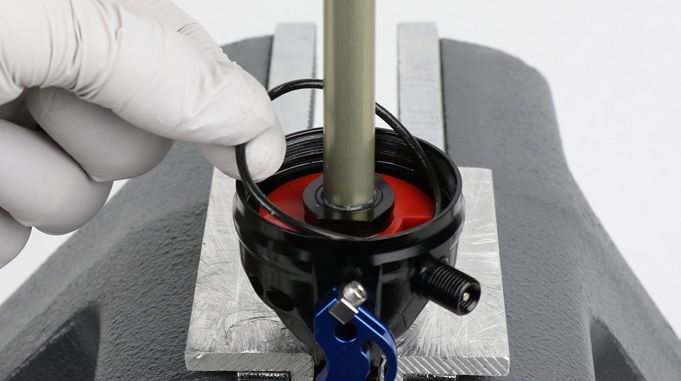
Remote Cable and Housing Removal - Remote Only
Prior to servicing the rear shock, remove the remote cable and housing from the shock, then remove the shock from the bicycle frame according
to the bicycle manufacturer's instructions. For different remote routing options, consult the Remotes User Manual found on www.sram.com/service.
Replace the cable and housing after performing shock service (see the Remote Cable and Housing Installation section).

 P a r t s , To o l s , a n d S u p p l i e s
Safety and Protection Supplies                                           Common Tools
• Nitrile gloves                                                         • Cable and housing cutters
• Safety glasses                                                         • Hex wrench: 2 mm

 Remote Cable and Housing Removal
      Unlock the remote, if locked.
 1
      Cut the cable and loosen the set screw, then remove the cable from
      the eyelet.
      Discard the cable and housing, if needed.

                                                                                  Cable and housing cutters          2 mm

      90˚ remote shocks: For 200 hour service, a cable needs to be
      installed in the eyelet to keep the eyelet assembly together during
      service. Once the shock has been removed from the bicycle frame,
      install the cable into the remote cable stop, with the cable head pulled
      taut against the eyelet, and tighten the set screw.

                                                                                  90˚ remote shocks                  90˚ remote shocks       2 mm

                                                                                            Remote Cable and Housing Removal - Remote Only         10
Shock Eyelet Service
Mounting Hardware and Bushing Service
Prior to servicing the rear shock, remove it from the bicycle frame according to the bicycle manufacturer's instructions. Once the shock is removed
from the bicycle, remove the mounting hardware before performing any service.
P a r t s , To o l s , a n d S u p p l i e s
Parts RockShox Tools
• RockShox SIDLuxe 50 or 200 Hour Service Kit • RockShox 1/2" x 1/2" rear shock bushing removal/installation tool
Safety and Protection Supplies Lubricants and Fluids
• Apron • RockShox Dynamic Seal Grease
• Clean, lint-free shop towels Common Tools
• Nitrile gloves • Bench vise with aluminium soft jaws
• Safety glasses • Open end wrenches: 13 mm (2)
• Adjustable wrench
Mounting Hardware Removal
NOTICE
To prevent damage to the shock, use aluminium soft jaws and position the eyelet in the vise so that the remote cable stop and adjustment knobs are
clear of the vise jaws.
Some mounting hardware is easily removed using only your fingers. Try to
remove the end spacers with your fingernail or small screwdriver, then push
the bushing pin out of the bushing. If this works, continue to the next section.
If you are unable to remove the mounting hardware using your fingers, use
the RockShox rear shock bushing removal/installation tool.
Catcher Push pin
Threaded rod
Rear shock bushing removal/installation tool
Thread the small end of the push pin onto the threaded rod until the
1 rod is flush or slightly protrudes from the hex-shaped end of the
push pin.
Shock Eyelet Service 11Insert the threaded rod through the shaft eyelet until the push pin rests
2 against the bushing pin.
Thread the large, open end of the catcher along the rod until it rests on
the end spacer.
Clamp the catcher in a vise or hold it secure with a 13 mm open
3 end or adjustable wrench.
NOTICE
Do not scratch the air can as you turn the wrench.
Use a second 13 mm wrench to thread the push pin along the rod until
it stops against the end spacer.
Unthread the push pin from the threaded rod to remove the end
spacer and the bushing pivot pin.
13 mm 13 mm
If the bushing pin does not remove easily, reinsert the threaded rod
4 and push pin back through the eyelet shaft.
Thread the large, open end of the catcher along the rod until it rests
against the shaft eyelet.
Use a 13 mm wrench to thread the push pin along the rod until it stops
against the end spacer.
13 mm 13 mm
Mounting Hardware Removal 12Unthread the catcher from the threaded rod.
5
Remove the end spacer and bushing pin from the tool.
Repeat steps 2-4 for the damper eyelet.
Set the mounting hardware aside until you have finished servicing
the shock.
Mounting Hardware Removal 13Eyelet Bushing Removal
To replace damaged or worn out bushings, use the RockShox rear shock bushing removal/installation tool.
Insert the threaded rod through the shaft eyelet until the base of the
1 push pin rests against the bushing.
Thread the large, open end of the catcher onto the rod until it rests on
the eyelet.
Clamp the catcher in a vise or hold it secure with a 13 mm wrench.
2
Use a second 13 mm wrench to thread the push pin along the rod until
the push pin pushes the eyelet bushing out of the eyelet.
13 mm 13 mm
Unthread the catcher from the threaded rod. Remove the tool from the
3 shaft eyelet and discard the old bushing.
Repeat steps 1-3 for the other eyelet.
Set the bushings aside until you have finished servicing
your shock.
To replace the eyelet bushings and mounting hardware, go to Shock Eyelet Assembly.
Eyelet Bushing Removal 14SIDLuxe Service
Prior to servicing your rear shock, remove it from the bicycle frame according to the bicycle manufacturer's instructions. Once the shock is removed
from the bicycle, remove the mounting hardware before performing any service (see the Mounting Hardware and Bushing Service section).
P a r t s , To o l s a n d S u p p l i e s
Parts RockShox Tools
• RockShox SIDLuxe 50 or 200 Hour Service Kit • RockShox SIDLuxe Air Valve Adapter Tool
Safety and Protection Supplies • SIDLuxe IFP Height Tool
• Apron • SIDLuxe Body Vise Block
• Clean, lint-free shop towels Common Tools
• Nitrile gloves • Bench vise with aluminium soft jaws
• Oil pan • Cone wrench: 18 mm
• Safety glasses • Crowfoot socket wrenches: 13 mm, 18 mm, 19 mm
Lubricants and Fluids • Flat blade screwdriver
• Maxima PLUSH 7wt Suspension Oil • Hex wrenches: 2 mm, 2.5 mm, 5 mm
• Maxima Extra 15w50 Suspension Oil (Pillow pack included in service kit) • Hex bit sockets: 2 mm, 5 mm
• RockShox Suspension Cleaner or Isopropyl alcohol • Open end wrenches: 13 mm, 19 mm
• RockShox Dynamic Seal Grease (Pillow pack included in service kit) • Pick
Bicycle Tools • Strap wrench
• Schrader valve core tool • Torque wrench
• High Pressure Shock Pump 600 psi
⚠ WARNING
Before disassembly or service of any air system remove the air pressure from all air chambers and remove the air valve cores.
If your shock will not return to full extension, do not attempt to service or disassemble your shock. Attempting to service a shock that will not return
to full extension can cause severe and/or fatal injuries. Send the shock to an authorized RockShox dealer for further service.
SAFETY INSTRUCTIONS
Always wear safety glasses and nitrile gloves when working with suspension fluid.
Place an oil pan on the floor underneath the area where you will be working on the shock.
SIDLuxe Service 1550/200 Hour Service Air Can Removal
To record your adjustment settings, rotate the red rebound adjuster
1 counter-clockwise until it stops, while counting the number of detent
clicks. This will assist you with post-service set up.
Remote: The blue compression circuit is unlocked by default once the
remote cable is removed.
RL: Rotate the blue compression lever to the unlocked position.
Remote 2.5 mm
RL 2.5 mm RL
Record your air pressure setting to assist with post-service set up.
2
Remove the air valve cap by hand. Lightly depress the Schrader valve
and slowly release all air pressure from the air can.
⚠ CAUTION
Slowly release the air from the air can to make sure the air is removed
from both chambers. Quickly releasing the air can trap air in the
negative chamber and cause the air can to forcefully eject from the
shock upon disassembly.
Do not disassemble a pressurized shock, this can cause suspension
fluid or debris to forcefully eject from the shock. Wear safety glasses.
Small hex
Use a Schrader valve tool to remove and reinstall the valve core from
the valve body to make sure all air has been removed.
Schrader valve tool
Air Can Removal 16Clamp the shaft eyelet into a vise, with the shock positioned
3 horizontally.
NOTICE
To prevent damage to the shock, use aluminium soft jaws and
position the eyelet in the vise so that the remote cable stop and
adjustment knobs are clear of the vise jaws.
Remove the sag indicator.
4
Insert a shop towel through the damper body eyelet to prevent the air
5 can from forcefully ejecting from the shock.
⚠ CAUTION- EYE HAZARD
The air can may still have air pressure in the negative chamber, which
may cause the air can to forcefully eject from the shock upon
disassembly. Wear safety glasses.
Use a strap wrench to remove the air can. Wrap the strap around the
6 section of the air can furthest from the shaft eyelet. Turn the wrench
counter-clockwise to unthread the air can.
Vacuum pressure will increase as you pull the air can along the
damper body, and will suddenly release when the air can is pulled
over the air piston.
Slowly pull the air can along the damper body, remove the shop towel,
and remove the air can.
NOTICE
Do not place the strap wrench on the air can decal.
Strap wrench
Air Can Removal 17B o t t o m l e s s Tu n i n g
Bottomless Tokens reduce air volume in your rear shock and create
greater progression at the end of the shock's travel. Add or remove
Tokens to tune your shock's bottomless feel.
Bottomless Tokens (1) 1 Token or (1) 2 Token max
1 Token 2 Token
Bottomless Token Installation: Clamp the damper body eyelet into the
vise.
Align the set screw openings on the Token and the seal head/air
piston, then slide the Token onto the seal head/air piston. Install the set
screw and tighten.
Bottomless Token 2 mm 0.68 N·m (6 in-lb)
Token Removal: Clamp the damper body eyelet into the vise.
Loosen and remove the Token set screw, then remove the Token from
the shaft.
2 mm Bottomless Token
Bottomless Tuning 1850/200 Hour Service Air Can Service
Remove the o-ring on the outside of the air can.
1
Clean the air can threads and eyelet body threads.
Apply a light layer of grease and install a new o-ring.
Remove the air can wiper seal located in the top groove.
2
Remove the backup ring from the second groove inside the air can.
3
Air Can Service 19Pierce and remove the quad seal from the bottom of the second
4 groove in the air can.
Clean the inside of the air can. Remove a glove and use your finger
5 to inspect the inside and outside of the air can for scratches, dents,
or other surface deformations. Replace the air can if it is scratched or
damaged.
Install a new quad seal by inserting one end into the deepest groove in
6 the air can, then push the remainder of the ring into the groove.
Install a new backup ring by inserting one end into the air can, then
Install
7 push the remainder of the ring into the can so that it rests on top of the
quad seal.
Air Can Service 20Orient the new wiper seal step side up. Install it into the wiper seal
8 groove at the top of the air can.
Apply a small amount of RockShox Dynamic Seal Grease to the quad
9 seal, backup ring, and wiper seal.
Set the air can aside.
Clamp the shaft eyelet vertically in the vise.
10
Remove the seal head/air piston quad ring seal and glide rings.
Clean the seal head/air piston.
Install a new quad ring seal and glide rings in the following orientation:
the thick glide ring closest to the shaft eyelet, the seal head/air piston
quad ring seal in the middle, and the thin glide ring closest to the
damper body eyelet.
To continue with the 50 Hour Service go to Air Can Installation.
To continue with the 200 Hour Service go to Damper Body Service.
Air Can Service 21200 Hour Service Damper Body Service
Remove the damper air/nitrogen fill port cap. Depress the Schrader
1 valve and release all air pressure from the damper.
Once the pressure has been released, depress the Schrader valve a
second time. If the Schrader valve is able to move, the shock has been
completely depressurized.
If the Schrader valve does not move at all, the shock is still
pressurized and will need to be sent to an authorized RockShox
dealer for further service.
⚠ CAUTION - EYE HAZARD
Verify all pressure is removed from the shock before proceeding.
Failure to do so can cause the damper body to separate from the
shaft eyelet at a high velocity. Wear safety glasses. Schrader valve tool Small hex
Remove the Schrader valve core from the damper air/nitrogen fill port.
2
Schrader valve tool
Remove the Bottomless Token, if installed.
3
2 mm Bottomless Token
Clamp the damper eyelet into the vise.
4
Damper Body Service 22Remove the bleed screw, located in the seal head/air piston.
5
2 mm
Wrap a shop towel around the damper body.
6
Loosen the seal head/air piston assembly from the damper body and
remove the assembly.
⚠ CAUTION - EYE HAZARD
If fluid is foaming from the damper body when the seal head/air piston
is loosened, the IFP seal has failed and the fluid inside the damper
is pressurized. This can cause the seal head/air piston assembly and
damper fluid to forcefully eject from the damper body. Cover the
seal head/air piston assembly with a shop towel and slowly loosen
the assembly to allow the pressurized fluid to leak out between the
damper body and seal head/air piston assembly.
Fluid will spill from the damper body. 19 mm
Remove the damper body from the vise and pour the fluid
7 into an oil pan.
Damper Body Service 23200 Hour Service Piston Service
90˚ remote shocks: Make sure a shift cable is installed in the eyelet
1 during piston and damper service.
2 mm
Clamp the shaft eyelet into the vise.
2
NOTICE
Remote shocks: To prevent damage to the shock, use aluminium soft
jaws and position the eyelet in the vise so that the remote cable stop
and lockout pulley are clear of the vise jaws.
Move the seal head/air piston assembly down.
3
Hold the piston assembly in place and remove the piston cap and valve
cup.. Set the valve cup and piston cap aside.
cup
The piston cap may loosen instead of the valve cup. Both instances
are normal. Set it aside and continue to the next step.
18 mm cone wrench 5 mm
Valve cup and piston cap Piston cap
Piston Service 24Loosen the piston bolt, then remove the piston assembly.
4
Be sure to keep the main piston assembly parts in the same order.
NOTICE
Keep all the parts together and set them aside. If the main piston
assembly is disassembled, it will need to be replaced.
18 mm cone wrench
NOTICE
Do not allow the detent ball to separate from the compression rod.
If the detent ball does seaparate from the compression rod, apply
grease to the detent ball and install it.
Detent ball
Remove the seal head/air piston.
5
Remove the bottom out bumper and the bottom out washer from the
6 damper shaft.
Piston Service 25Use a flat blade screwdriver to release the tabs on the travel spacer, if
7 installed. Do not remove the volume equalizer, if installed.
Not all shocks have travel spacers or volume equalizers installed.
NOTICE
Do not scratch the damper shaft or eyelet threads when removing the
travel spacer. Scratches can cause leaks.
Flat blade screwdriver Flat blade screwdriver
Remove the o-ring located inside the shaft eyelet threads.
8
Apply a light layer of grease and install a new o-ring inside the shaft
eyelet threads.
Piston Service 26Install the travel spacer, if included, then install the bottom out spacer
9 and bottom out bumper.
Remove the shock from the vise.
Pierce and remove the internal seal o-ring located in the internal seal
10 gland of the seal head/air piston.
Apply grease and install a new internal seal o-ring into the seal gland.
Remove the inner o-ring, located at the base of the threads in the seal
11 head/air piston.
Apply grease and install a new inner o-ring into the seal head/air
piston.
Piston Service 27Gently clamp the seal head into the vise. Push the compression ball
12 out of the backside of the seal head through the bleed port.
Do not replace the compression ball at this time; you will
replace it later.
Do not reuse the compression ball.
1.5 mm
Clamp the shaft eyelet into a vise and install the seal head/air piston
13 onto the damper shaft.
NOTICE
Remote shocks: To prevent damage to the remote cable stop,
position the eyelet in the vise so that the remote cable stop is clear of
the vise jaws.
Remove the o-ring from the middle of the compression rod on the main
14 piston assembly.
Install a new o-ring.
Apply a thin layer of grease to the detent ball and the middle o-ring on
the compression rod.
RockShox Dynamic Seal Grease RockShox Dynamic Seal Grease
Piston Service 28Install the main piston assembly into the damper shaft.
15
The open piston can only be installed one way; rotate the open piston
until it settles into place on the shaft. Use your fingers to squeeze the
shims and center the shim stack until the rest of the piston assembly
settles into place.
Tighten the piston bolt.
Be sure to keep the main piston assembly parts in the same order.
NOTICE
If the shims are not centered and in the correct order, the shock will
not perform properly.
18 mm cone wrench 18 mm 4.5 N·m (40 in-lb)
Press the valve spool down.
16
NOTICE
If the valve spool is not pressed down, the shock cannot be bled.
Piston Service 29Thread the valve cup with the piston cap onto the piston assembly, and
17 tighten.
If the piston cap was removed from the valve cup during removal,
thread the piston cap into the valve cup, and tighten the assembly.
Valve cup with piston cap Piston cap
18 mm 2.8 N·m (25 in-lb) 5 mm
Piston Service 30200 Hour Service IFP and Damper Body Service
Wrap a shop towel around the end of the damper body. Thread the
1 SIDLuxe air valve adapter tool into a shock pump. Thread the pump
and adapter into the air fill port.
Pump air into the damper body to force the IFP out of the damper body
and into the shop towel.
RockShox SIDLuxe Air Valve Adapter Tool and shock pump
Clean the inside and outside of the damper body.
2
Remove a glove and use your finger to inspect the inside and outside
of the damper body for scratches, dents, or other surface deformations.
If any deformations are found, the damper body will need to be
replaced.
Remove and replace the IFP o-ring.
3
Apply grease and install the IFP o-ring.
IFP and Damper Body Service 31Install the IFP into the damper body with the stepped side visible. Use
4 the SIDLuxe IFP Height Tool to push the IFP to the depth specified in
the table below.
Make sure the damper Schrader valve core is removed from the
damper body. This will help with setting the IFP height.
Measure the IFP depth from the lowest part of the IFP.
Shock Stroke IFP Insertion Depth
27.5-35 mm 46 mm
37.5-45 mm 55 mm
47.5-50 mm 61 mm
Shock stroke
SIDLuxe IFP Height Tool SIDLuxe IFP Height Tool
Install the Schrader valve core into the damper air/nitrogen fill port.
5
Schrader valve tool
IFP and Damper Body Service 32200 Hour Service Shock Assembly and Bleed
Slide the seal head/air piston until it stops at the end of the damper
1 shaft.
Clamp the damper body into the SIDLuxe Body Vise Block.
2
Tighten the vise firmly enough so that the IFP cannot move in the
damper body. Check this by using your finger to push on the IFP.
If the IFP does move, use a shock pump to push out the IFP, and then
reset it to the depth specified in the table.
Do not overtighten the vise so that the damper body gets crushed.
NOTICE
The SIDLuxe Body Vise Block holds the IFP in place. Failure to use
the vise block when clamping the damper body into the vise may
result in improper IFP height. Improper IFP height can cause the
damper to fail. SIDLuxe Body Vise Block
Wrap a clean shop towel around the damper body.
3
Pour new Maxima PLUSH 7wt Suspension Oil into the damper body
until it is level with the top.
Maxima PLUSH 7wt Suspension Oil is backwards compatible with
RockShox 7wt suspension oil.
Maxima PLUSH 7wt Suspension Oil
Make sure that the compression ball is removed from the
4 seal head/air piston (page
(page 28).
28).
With the seal head/air piston positioned at the end of the damper shaft,
install the seal head/air piston onto the damper body.
Do not press down on the shaft eyelet or damper shaft while
installing the seal head; this can move the piston/shaft assembly,
causing too much fluid to displace out of the damper body.
Fluid will be displaced out of the bleed port.
Shock Assembly and Bleed 33Tighten the seal head/air piston.
5
Install the crowfoot onto the torque wrench at a 90° angle to the
handle to ensure an accurate torque reading.
19 mm 28 N·m (248 in-lb)
Allow air bubbles to escape from the bleed port in the seal head.
6
Insert the new compression ball into the bleed port.
Thread the bleed screw into the bleed port until you feel it touch the
7 compression ball, then tighten the bleed screw an additional ½ turn.
NOTICE
Overtightening the bleed screw can damage the compression ball.
Remove the damper body from the SIDLuxe Body Vise Block.
2 mm
Pressurize the damper body.
8
If you have the proper fill equipment, you may substitute air with
nitrogen.
Once you have pressurized the shock, remove the air valve adapter
tool from the air fill port before removing it from the shock pump.
Separating the pump from the adapter first will cause all of the air to
escape from the shock.
Shock pump 500 psi SIDLuxe adapter tool
Shock Assembly and Bleed 34Install the damper air/nitrogen fill port cap.
9
Schrader valve tool
Remove the shock from the vise.
10
Spray the damper assembly with isopropyl alcohol and clean it with
a shop towel.
Shock Assembly and Bleed 3550/200 Hour Service Air Can Installation
Clamp the shaft eyelet into a vise, with the shock positioned
1 horizontally.
Grease the seal head/air piston seals.
Inject 0.5 mL of Maxima Extra 15w50 Suspension Oil, approximately 1/4
2 the pillow pack, into the air can before installing the air can onto the
damper. Firmly press the air can down until the sealhead/air piston is
inserted into the air can.
15w50 0.5 mL
Inject another 0.5 mL of Maxima Extra 15w50 Suspension Oil, or
3
another 1/4 of the pillow pack, into the air can.
NOTICE
Do not use the entire pillow pack. If the air can is lubricated properly,
the pillow pack should be half full.
15w50 0.5 mL
Press the air can onto the damper then thread it onto the shaft eyelet
4 until it is hand tight.
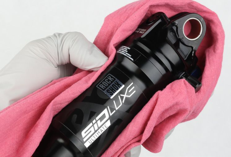
Clean the outside of the air can.
Air Can Installation 36Remove the shock from the vise. Turn it over and clamp the damper
5 body eyelet in the vise.
Stabilize the air can with a strap wrench to prevent it from rotating.
Tighten the air can.
13 mm 4.5 N·m (40 in-lb)
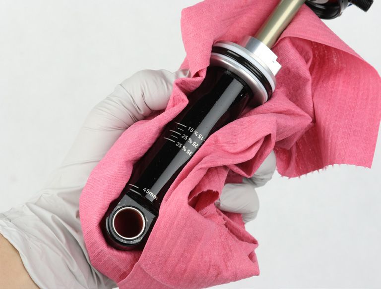
Remove the shock from the vise. Spray isopropyl alcohol on the shock
6 and clean it with a shop towel.
Install the sag indicator o-ring.
7
Air Can Installation 37Shock Eyelet Assembly
Eyelet Bushing Installation
Apply a light layer of grease to the outside of the new bushing.
1
Position the shaft eyelet and eyelet bushing between the soft jaws of a
2 vise. Slowly turn the vise handle to begin pressing the eyelet bushing
into the shaft eyelet.
Check the alignment of the bushing as it enters the eyelet. If the
bushing starts to enter the eyelet at an angle, remove the bushing
from the eyelet, regrease the bushing, and repeat this step until the
bushing enters the eyelet straight.
Continue to press the eyelet bushing until it is seated in the shaft
eyelet.
Remove the shock from the vise and repeat the installation process for
the other bushing and eyelet.
Shock Eyelet Assembly 38Mounting Hardware Installation
Some mounting hardware is easily installed using only your fingers. Press the bushing pin into the shock eyelet bushing until the pin protrudes from
both sides of the eyelet an equal amount. Next, press an end spacer, large diameter side first, onto each end of the bushing pin. If this works, you
have completed mounting hardware and bushing service.
If you are unable to install your mounting hardware using your fingers, use the RockShox rear shock bushing removal/installation tool.
Thread the small end of the push pin onto the threaded rod until the
1 push pin is flush or slightly protrudes from the hex-shaped end of the
push pin.
Insert the threaded rod through the bushing pin then through the shaft
2 eyelet so that the bushing pin is positioned between the push pin and
the eyelet.
Thread the large, open end of the catcher onto the rod until it rests on
3 the eyelet.
Mounting Hardware Installation 39Clamp the catcher in a vise or hold it secure with a 13 mm wrench.
4
Use a second 13 mm wrench to thread the push pin along the rod until
it pushes the bushing pin into the shock eyelet bushing.
Continue to thread the push pin until the bushing pin protrudes from
both sides of the eyelet an equal amount.
You may need to unthread the catcher slightly to check the bushing
pin spacing.
13 mm 13 mm
Press an end spacer, large diameter side first, onto each end of the
5 bushing pin.
Reinstall the shock to your bicycle frame according to the bicycle
6 manufacturer's instructions.
Use a shock pump to pressurize the shock to the recorded air pressure plus 20%. After adding air to the shock, the pressure will need to be
7 equalized between the shock chambers.
Record the air pressure value on the pump, then unthread it from the shock. Slowly but firmly press or sit on the saddle to compress the shock
until there is a hissing sound. This sound indicates air transfer between chambers.
Reinstall the pump and pressurize the shock to the desired air pressure. Record the air pressure, then unthread it from the shock. Repeat this
process until you reach the desired amount of sag, then install the valve cap.
NOTICE
When pressurizing the shock, do not exceed maximum pressure rating.
The pump must be removed from the shock prior to checking sag to avoid damage to the pump.
This concludes the service for the RockShox SIDLuxe rear shock.
Mounting Hardware Installation 40Remote Cable and Housing Installation - Remote
This installation procedure shows the 90˚ remote shock. For different remote routing options, consult the Remotes User Manual on
www.sram.com/service.
P a r t s , To o l s , a n d S u p p l i e s
Parts Common Tools
• Shift cable and housing • 2 mm hex wrench
Safety and Protection Supplies • 2 mm hex bit socket
• Safety glasses • Torque wrench
• Nitrile gloves • Cable and housing cutters
Remote Cable and Housing Installation
After the housing has been routed and installed on the bicycle, thread
1 the cable through the housing and remote cable stop, then insert the
housing into the remote cable stop
Do not use a housing ferrule; the housing can be installed directly into
the remote cable stop.
Pull the cable taut, then tighten the screw.
2
2 mm 0.9 N·m (8 in-lb)
Remote Cable and Housing Installation - Remote 41Cut the cable to length, then install the cable end cap.
3
Cable and housing cutters
Remote Cable and Housing Installation 42These are registered trademarks of SRAM, LLC: 1:1®, Accuwatt®, Avid®, AXS®, Bar®, Blackbox®, BoXXer®, DoubleTap®, Elita®, eTap®, Firecrest®, Firex®, Grip Shift®, GXP®, Hammerschmidt®, Holzfeller®, Hussefelt®, i-Motion®, Judy®, Know Your Powers®, NSW®, Omnium®, Pike®, PowerLock®, Quarq®, Qollector®, RacerMate®, Reba®, Rock Shox®, Ruktion®, Service Course®, ShockWiz®, SID®, Single Digit®, Speed Dial®, Speed Weaponry®, Spinscan®, SRAM®, SRAM APEX®, SRAM EAGLE®, SRAM FORCE®, SRAM RED®, SRAM RIVAL®, SRAM VIA®, Stylo®, Torpedo®, The Power of Bicycles®, Truvativ®, Varicrank®, Velotron®, World Bicycle Relief®, X0®, X01®, X-SYNC®, XX1®, Zed tech®, ZIPP® These are registered logos of SRAM, LLC: These are trademarks of SRAM, LLC: 10K™, 1X™, 202™, 30™, 35™, 302™, 303™, 404™, 454™, 808™, 858™, 3ZERO MOTO™, ABLC™, AeroGlide™, AeroBalance™, AeroLink™, Airea™, Air Guides™, AKA™, AL-7050-TV™, Automatic Drive™, Automatix™, AxCad™, Axial Clutch™, BB5™, BB7™, BB30™, Bleeding Edge™, Blipbox™, BlipClamp™, BlipGrip™, Blips™, Bluto™, Bottomless Tokens™, Cage Lock™, Carbon Bridge™, Centera™, Charger 2™, Charger™, Clickbox Technology™, Clics™, Code™, Cognition™, Connectamajig™, Counter Measure™, DD3™, DD3 Pulse™, DebonAir™, Deluxe™, Deluxe Re:Aktiv™, Descendant™, DFour™, DFour91™, Dig Valve™, DirectLink™, Direct Route™, DOT 5.1™, Double Decker™, Double Time™, Dual Flow Adjust™, Dual Position Air™, DUB™, DZero™, E300™, E400™, Eagle™, E-Connect4™, E-matic™, ErgoBlade™, ErgoDynamics™, ESP™, EX1™, Exact Actuation™, Exogram™, Flow Link™, FR-5™, Full Pin™, Gnar Dog™, Guide™, GX™, Hard Chrome™, Hexfin™, HollowPin™, Howitzer™, HRD™, Hybrid Drive™, Hyperfoil™, i-3™, Impress™, Jaws™, Jet™, Kage™, Komfy™, Level™, Lyrik™, MatchMaker™, Maxle™, Maxle 360™, Maxle DH™, Maxle Lite™, Maxle Lite DH™, Maxle Stealth™, Maxle Ultimate™, Micro Gear System™, Mini Block™, Mini Cluster™, Monarch™, Monarch Plus™, Motion Control™, Motion Control DNA™, MRX™, Noir™, NX™, OCT™, OmniCal™, OneLoc™, Paragon™, PC-1031™, PC-1110™, PC-1170™, PG-1130™, PG-1050™, PG-1170™, Piggyback™, Poploc™, Power Balance™, Power Bulge™, PowerChain™, PowerDomeX™, Powered by SRAM™, PowerGlide™, PowerLink™, Power Pack™, Power Spline™, Predictive Steering™, Pressfit™, Pressfit 30™, Prime™, Qalvin™, R2C™, RAIL™, Rapid Recovery™, Re:Aktiv ThruShaft™, Recon™, Reverb™, Revelation™, Riken™, Rise™, ROAM™, Roller Bearing Clutch™, RS-1™, Sag Gradients™, Sawtooth™, SCT - Smart Coasterbrake Technology, Seeker™, Sektor™, SHIFT™, ShiftGuide™, Shorty™, Showstopper™, SIDLuxe™, Side Swap™, Signal Gear Technology™, SL™, SL-70™, SL-70 Aero™, SL-70 Ergo™, SL-80™, Sl-88™, SLC2™, SL SPEED™, SL Sprint™, Smart Connect™, Solo Air™, Solo Spoke™, SpeedBall™, Speed Metal™, SRAM APEX 1™, SRAM Force 1™, SRAM RIVAL 1™, S-series™, Stealth-a-majig™, StealthRing™, Super-9™, Supercork™, Super Deluxe™, Super Deluxe Coil™, SwingLink™, SX™, SX Eagle™, TaperCore™, Timing Port Closure™, Tool-free Reach Adjust™, Top Loading Pads™, Torque Caps™, TRX™, Turnkey™, TwistLoc™, Tyrewiz™, UDH™, VCLC™, Vivid™, Vivid Air™, Vuka Aero™, Vuka Alumina™, VukaBull™, Vuka Clip™, Vuka Fit™, Wide Angle™, WiFLi™, X1™, X5™, X7™, X9™, X-Actuation™, XC™, X-Dome™, XD™, XD Driver Body™, XDR™, XG-1150™, XG-1175™, XG-1180™, XG-1190™, X-Glide™, X-GlideR™, X-Horizon™, XLoc Sprint™, XX™, Yari™, Zero Loss™ Specifications and colors subject to change without prior notice. © 2020 SRAM, LLC This publication includes trademarks and registered trademarks of the following companies: Maxima Racing Oils® is a registered trademark of Maxima Racing Oils PLUSH™ and Extra™ are trademarks owned by Maxima Racing Oils
ASIAN HEADQUARTERS                WORLD HEADQUARTERS                 EUROPEAN HEADQUARTERS
SRAM Taiwan                       SRAM LLC                           SRAM Europe
No. 1598-8 Chung Shan Road        1000 W. Fulton Market, 4th Floor   Paasbosweg 14-16
Shen Kang Hsiang, Taichung City   Chicago, Illinois 60607            3862ZS Nijkerk
Taiwan R.O.C.                     U.S.A.                             Niederlande
You can also read