27 Air-to-Water Heat Pump Systems - Caleffi ...
←
→
Page content transcription
If your browser does not render page correctly, please read the page content below
TM

JOURNAL OF DESIGN INNOVATION FOR HYDRONIC AND PLUMBING PROFESSIONALS
                                                                       27
                                                                       July 2020

Air-to-Water
Heat Pump Systems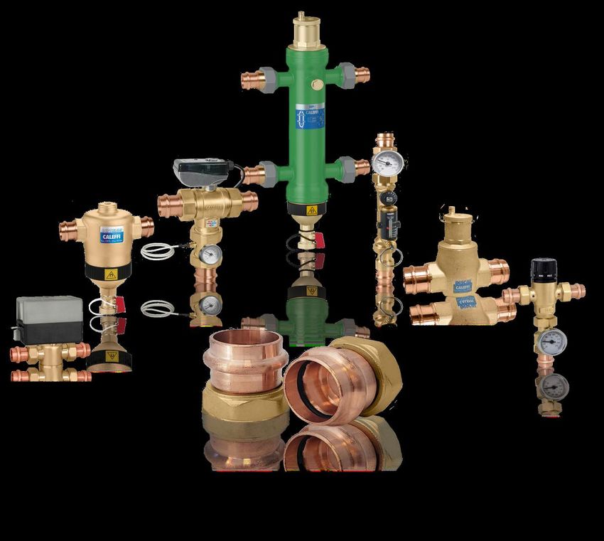
Press Connections
        Available on our most popular products
        • Years of proven Caleffi reliability in plumbing and hydronic product applications.
        • Exclusive LEAK DETECTION feature reveals leakage point during system
           testing if a connection remains unpressed.
        • Versatile union connections feature integral copper tail-piece construction.

                        Components for today's modern hydronic systems

Heating & Cooling

www.caleffi.com - Milwaukee, WI USA
FROM THE GENERAL MANAGER & CEO
Dear Plumbing and Hydronic Professional,
There are many types of heat pumps. The one most of us are familiar with is our
kitchen refrigerator. It removes heat from food and pumps it back to the kitchen.
Over the past three decades refrigerator manufacturers
have continually introduced new ways to reduce the
energy used by their products. No longer is a homeowner’s
decision to replace their refrigerator based mostly on its
age. Now, the electrical energy savings offered by the
latest technology can justify the purchase - even though
their current refrigerator is still functioning.
The design of heat pumps that supply space conditioning
and domestic water heating has also improved
dramatically. Enhanced vapor injection, variable speed
inverter compressors, electronic expansion valves and other state-of-the-art
technologies have been integrated into many modern heat pumps . The resulting
efficiency gains now allow air-source heat pumps to be used in cold Northern
climates, even when outside temperatures fall below 0 ºF. And because they
operate on electricity, rather than fossil fuel, they are well-positioned for today’s
focus on carbon reduction driven by changing social attitudes and government
policies.
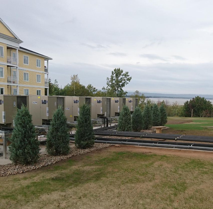
This issue of idronics deals with “air-to-water” heat pumps that heat buildings
by absorbing low temperature heat from outside air and delivering it, at higher
temperatures, to a hydronic distribution system. These heat pumps combine the
advantages of modern air-source heat pump technology with the unsurpassed
comfort of hydronic heating and cooling. They are widely used in Europe and
Asia, and represent a growing market opportunity within North America.
We hope you enjoy this issue of idronics and encourage you to send us any
feedback by e-mailing us at idronics@caleffi.com.
For prior issues please visit us at www.caleffi.us, and click on the icon. There
you can download the PDF files. You can also register to receive hard copies of
future issues.
Mark Olson
General Manager & CEO
3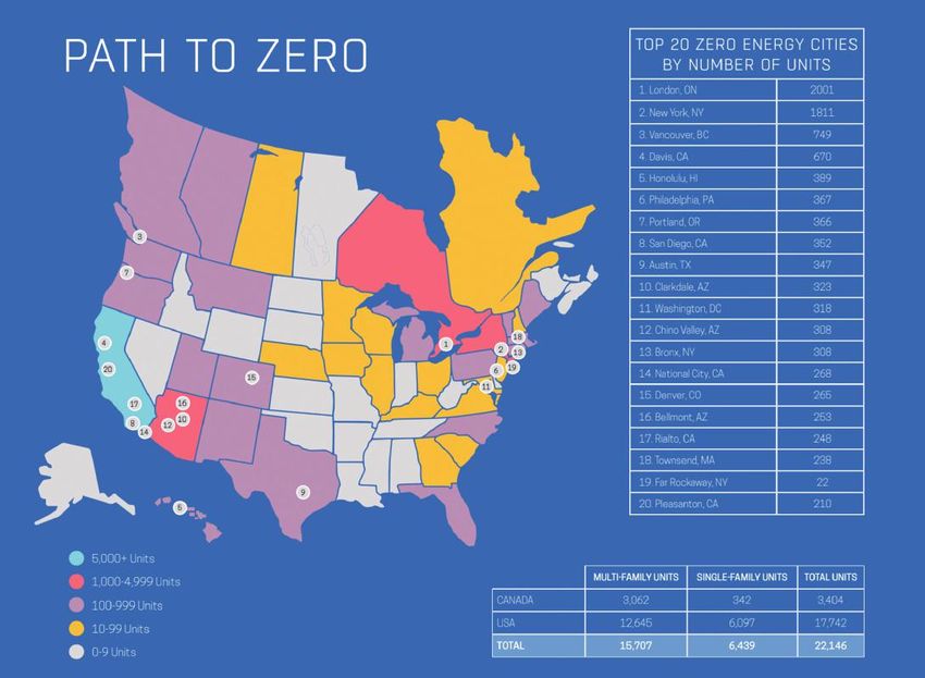
TABLE
TABLE OFCONTENTS
OF
TABLE CONTENTS
OF CONTENTS
55
5Introduction
Introduction
Introduction
What
Whatis ais heat
a heatpump?
heat pump? Cold climate
Cold climateair-source heat
air-source heat
What
History ofis heat
a pump?
pumps Cold
pumps climate air-source heat
5
History of heat pumps pumps
5 Performance
History
Introductionof heat pumps
limitations pumps
Modern air-to-water heat pumps
Introduction
Performance
Performance limitations
limitations Modern
Modern air-to-water
air-to-water heat
heat pumps
pumps
27
26
1010 77Heat
10Heat pump
Heat pump
pump
Pipe
Pipe &
operating fundamentals
operating
operating
& fitting
fitting
fundamentals
fundamentals
nomenclature
nomenclature
Non-reversible
Non-reversiblevs.vs.
Reversible heat Energy efficiency ratio
Pipe
Pipe vs.
vs. tube
Non-reversible
pumps vs. Reversible
tube Reversible heat
heat Energy
Energy
What
efficiency
doesefficiency
ratio
ratio
“tons” mean?
pumps
pumps
Pipe size What
What does
does “tons”
“tons” mean?
mean?
Pipe
Heating
Heating size
mode
mode thermal performance
thermal performance Enhanced
Enhanced vapor injection
vapor injection
Heating
Pipe mode
fitting thermal performance
terminology Enhanced vapor injection
January 2020 Pipe
Cooling
Cooling
Cooling fitting
mode
mode
mode terminology
thermal performance
thermal
thermal performance
performance
Defrosting
Defrosting
Defrosting
January
July 2020
July 2020
2020 Biomass
Biomass boilers
boilers
2020
Biomass boilers
20Energy
Energy
Energy trends
trends
trends
Couplings
Couplings
&
& their
& their
their effect
effect onon
effect hydronic
hydronic
on heat
heat
hydronic sources
sources
heat sources
1. 1.
1. Government
Government
Elbows policy
Elbows
Government policy
policy supporting
supporting
supporting 5. 5. Lack
Lack
5. of of
Lack suitable
suitable
of combustion-based
combustion-based
suitable combustion-based heat
heat
heat
decarbonization:
decarbonization:
decarbonization: sources:
sources:
sources:
2. 2.
2. Financial
Financial
Financial incentives:
incentives:
incentives: 6. 6. Basic
Basic
6. service
service
Basic charges
charges
service charges &
& pricing
& pricing forfor
pricing for
3. Strong interest and impressive market natural gas:
12
3. 3.
Strong interest
Strong and
interest impressive
and market
impressive market natural gas:
natural gas:
12 Metal
Metal
growth pipe
growth
for
growth for
pipe
for joining
“net-zero”methods
buildings:&
buildings:
joiningbuildings:
“net-zero”
“net-zero”methods & materials
materials
7. 7. Safety
Safety
7. issues:
issues:
Safety issues:
4.
4. 4. Decreasing
Steel
Steel pipe
Decreasing pipe
Decreasing heating
heating
heating and
and cooling
cooling
and cooling loads:
loads:
loads: 8.
8. 8. Moratoriums
Moratoriums
Moratoriums on
onon natural
natural gas
natural gas expansion:
expansion:
gas expansion:
Stainless
Stainless
Advantages steel
steel pipe
pipe heat
Advantages
Advantages of of
of air-to-water
air-to-water
air-to-water heat pumps
pumps
heat pumps
Wrought
Wrought iron
iron pipe
pipe
1. 1.
1. Significantly
Significantly
Significantly lower
lower
lower installation
installation cost:
cost:
installation cost: 4. 4. Independent
Independent
4. Independentof of
of incentives:
incentives:
incentives:
2. 2. Black
Black iron
Noninvasive
2. iron
Noninvasive
Noninvasive
pipe
pipe
installation:
installation:
installation: 5. 5. Higher
Higher
5. netnet
Higher net COP:
COP:
COP:
3. 3.3. Cast
Ground
Ground
Ground iron
water
Castwater
iron
water pipe
protection:
protection:
pipe
protection: 6. 6. Savings
Savings
6. decrease
decrease
Savings decrease asas loads
loads
as decrease:
decrease:
loads decrease:
AA Technical
Technical Journal
Journal Copper
Copper waterwater tube
2828
tube
from
from 28Air-to-water
Air-to-water
Brassheat
Air-to-water
Brass heat
heat pump
pump
pump configurations
configurations
configurations
7. 7.
7. Influence
Influence
Influence
Bronze of of
of global
global
global markets:
markets:
markets: Other
Other air-to-water
air-to-water
Other heat
heat
air-to-water pump
pump
heat system
system
pump system
CALEFFI Bronzeair-to-water heat pumps
CALEFFI NORTH
NORTH AMERICA,
AMERICA, INC
INC Monobloc
Monobloc
Monobloc air-to-water
air-to-water
Metallurgical heat pumps
heat
joining pumps
methods
configurations
configurations
configurations
Freeze
Freeze
Freeze Metallurgical
protection
protection
protection joining
options
options
options methods
forfor monobloc
monobloc
for monobloc Integrated
Integrated
Integrated systems
systems
systems
3883
3883 W.
W. Milwaukee
Milwaukee Rd
Rd heat Soft
Soft
heat soldering
soldering
pumps
pumps Balance
Balance point
point
heat pumps Balance point
Brazing
Antifreeze-based
Brazing freeze
Antifreeze-based
Antifreeze-based freeze
freeze protection
protection
protection Climate
Climate considerations
considerations
Climate considerations
Milwaukee,
Milwaukee, Wisconsin
Wisconsin 53208
53208 Split system air-to-water heat pumps Spr
Split
Split Welding
system
systemair-to-water
Welding air-to-water heat pumps
heat pumps SprSpr
USA
USA interior
interior air-to-water
air-to-water
interior heat
heat
air-to-water pumps
pumps
heat pumps
46Heat
4646 Heat emitter optionsforfor air-to-water heat pump systems
29
Heat emitter
emitter options
options for air-to-water
air-to-water heat
heat pump
pump systems
systems
29Seasonal
Polymer
Seasonal
Polymer
Seasonal pipe
pipe joining
average cop
joining
average cop methods
methods &
& materials
materials Radiant
Radiant wall
wall panels
panels
Tel:
Tel: 414-238-2360
414-238-2360 average
Heated
cop
floor slabs
Radiant wall panels
Radiant ceiling panels
Polyvinyl
Polyvinyl
Heated
Heated floor
floor chloride
slabschloride tubing
slabs tubing (PVC)
(PVC) Radiant
Radiant ceiling
ceiling panels
panels
FAX: Underfloor tube
Chlorinated & plate radiant
&PolyVinyl panels
Chloride
panels tubing Panel
(CPVC) radiators
FAX: 414-238-2366
414-238-2366 Underfloor
Underfloor tube
Chlorinated
tube plate
& plate radiant
PolyVinyl
radiantChloride
panels tubing Panel
(CPVC)
Panel radiators
radiators
58 Design
5858Design
DesignHigh-Density
High-Density
details for Polyethylene
for air-to-water
air-to-water tubing
Polyethyleneheat
tubing
heat pump(HDPE)
(HDPE)
details
details for air-to-water pump
heattubing
pump
Cross-linked
Cross-linked
Low-temperature Polyethylene
Polyethylene
fin-tube tubing
baseboard (PEX)
(PEX) 2-Stage
Low-temperature fin-tube baseboard
Low-temperature fin-tube baseboard 2-Stage setpoint
setpoint control
2-Stage control
setpoint control
E-mail:
E-mail: idronics@caleffi.com
idronics@caleffi.com Cast
Cast Oxygen
iron
Oxygen
iron diffusion
radiators
diffusion
radiators 2-Stage
2-Stage outdoor
outdoor reset
reset control
control
Cast iron
Reducing radiators
Compositewater temperature
PEX-AL-PEX in existing
tubing 2-Stage outdoor
Auxiliary heat reset
source control
control logic within
Website: Composite
Reducing water PEX-AL-PEX
temperature in tubing
existing Auxiliary heat source control logic within
Website: www.caleffi.us
www.caleffi.us Reducing
systems water temperature
Polyethylene-raised
systems
in existing
temperature
Auxiliary
tubing the
(PE-RT)
the
heat
heat
heat
source
pump
pump
control logic within
Polyethylene-raised
Mounting temperature
systems outdoor heat pumps piping tubing (PE-RT)
the heat pump
Monitoring heat pump performance
Mounting outdoor heat pumps piping (PP-R) Monitoring
Mounting PolyPropylene-random
PolyPropylene-random
outdoor
connections heat pumps tubing
tubing
piping (PP-R) Monitoring
Domestic heatheat
water
pump
pump performance
performance
heating options
connections Domestic water heating options
BufferFusion
connections
Fusion
tanks joining
joining methods
methods Domestic water heating
desuperheater option options
To
To receive
receive future
future idronics
idronics issues
issues Buffer
Buffer tanks
tanks desuperheater
desuperheater option
option
Buffer
Buffer tank
tank piping
piping Indirect
Indirect tank
tank option
option
FREE,
FREE, register
register online
online 41
41DirtAuxiliary
Buffer
Dirt tank
Summary
Dirt
piping
separation
Summary
separation
separation
Indirect
Reverse
Reverse
Reverse
tank option
indirect
indirect
indirect
tank
tank
tank
option
option
option
Auxiliary heating
heating provisions
provisions On-demand
On-demand external
external heat
heat exchanger
exchanger option
option
www.caleffi.us Auxiliary
Controllingheating provisions
auxiliary heat On-demand
chilled external
water coolingheat exchanger
details chilled option
water
www.caleffi.us Controlling
Controlling auxiliary
auxiliary heat
heat chilled
chilled water
water cooling
cooling details
details chilled
chilled water
water
2-Stage
2-Stage room
room thermostat
thermostat terminal
terminal units
units
2-Stage room thermostat terminal units
73 System
7373System
© System examples
examples
© Copyright 2019
Copyright 2020
2019 examples
Preventing
Preventing unwanted
unwanted condensation
condensation System
System #4
#4
Preventing
System
System #1unwanted condensation
#1 System #4 #5
System
System #5
Caleffi
Caleffi North
North America,
America, Inc.
Inc. System
System
System#1#2
#2 System
System
System#5#6
#6
Printed: System
System#2#3 System #6
Summary
Printed: Milwaukee,
Milwaukee, Wisconsin
Wisconsin System
System #3
#3 Summary
Summary
USA
USA 82
82 Appendix
Appendix A:
A: component
component symbol
symbol legend
legend
82 Appendix A: component symbol legend
Disclaimer: Caleffi
Caleffi makes no
no warranty
warranty that
that the
the information
information presented in
in idronics meets
meets the
the mechanical, electrical
Disclaimer: makesjurisdiction. presented idronics mechanical, electrical or
or other
other code
code requirements
requirements
applicable
applicable within
within aa given
given jurisdiction. The
The diagrams
diagrams presented
presented in
in idronics
idronics are
are conceptual,
conceptual, and
and do
do not
not represent
represent complete
complete schematics
schematics forfor any
any
specific
specific installation. Local codes may require differences in design, or safety devices relative to those shown in idronics. It is
installation. Local codes may require differences in design, or safety devices relative to those shown in idronics. It is the
the responsibility
responsibility
4
444 N°
N° 55
55 giugno
giugno 2019
2019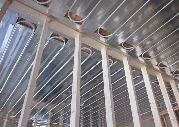
INTRODUCTION

                                                                low-temperature heat and which material receives the
WHAT IS A HEAT PUMP?
                                                                higher-temperature heat. This makes it possible for heat
Heat, by nature, always moves from an area of higher            pumps to heat and cool buildings. There are also many
temperature to an area of lower temperature. This               different configurations of heat pumps available depending
“natural” heat transfer takes place constantly all around       on the material from which low-temperature heat is being
us. Examples include:                                           absorbed, and the material into which higher-temperature
                                                                heat is being released.
• Heat leaving our skin and clothing surfaces, and trans-
ferring to cooler air surrounding us.                           When used to heat buildings, heat pumps can gather
                                                                low-temperature heat from sources such as outdoor air,
• Heat transferring from the inside of buildings to outside     ground water, lakes or ponds, or tubing buried in the earth.
air whenever the inside temperature is warmer than the          All of these sources provide “free” low-temperature heat.
outdoor temperature.
                                                                Heat pumps that extract low-temperature heat from outside
• A glass of cold iced tea placed on a countertop continu-      air are common in North America. They are appropriately
ally absorbing heat from warmer air surrounding it, as well     called “air-source” heat pumps. The vast majority of air-
as from the countertop, both of which are at higher tem-        source heat pumps currently in service are configured
perature than the tea.                                          to deliver higher-temperature heat through a forced-air
                                                                distribution system within the building. This leads to the
No machines or special techniques are needed to move            more specific classification of “air-to-air” heat pump.
heat from materials at higher temperature to materials at
lower temperature.                                              Heat pumps that extract low-temperature heat from
                                                                geothermal sources such as lakes, ponds, wells or tubing
Heat pumps were developed to reverse the “natural”              buried in the earth use water or an antifreeze solution to
direction of heat transfer. Their function is to move (e.g.,    convey heat from those sources to the heat pump. They
“pump”) heat from materials at lower temperature to             are thus classified as water-source heat pumps. Water-
materials at higher temperature.                                source heat pumps that deliver heat through a forced-
                                                                air system are more specifically called “water-to-air” heat
The low-temperature heat is gathered from some material         pumps. Those that deliver heat using a hydronic distribution
called the “source,” and then concentrated and released         system are known as “water-to-water” heat pumps.
into another material called the “sink.”
                                                                This issue of idronics deals with a specific heat pump
In some respects, a heat pump is similar to a refrigerator.     configuration that absorbs low-temperature heat from
The latter absorbs low-temperature heat from the food           outside air and delivers that heat, at higher temperatures, to
placed inside it. It then raises the temperature of the         a stream of water within a building. This type of heat pump
absorbed heat and releases it in the surrounding air.           is more specifically called an “air-to-water” heat pump.
Most heat pumps and refrigerators use a chemical
called a refrigerant that circulates within a closed circuit
                                                                HISTORY OF HEAT PUMPS
of components and changes phase between liquid and
                                                                Heat pumps are based on the principles of refrigeration,
vapor to “pump” heat from low-temperature materials into
                                                                which were first demonstrated by Scottish physician William
higher-temperature materials. The refrigerant is pushed
                                                                Cullen in 1755. Cullen developed an apparatus to create a
through the closed loop of components by an electrically
                                                                vacuum over a container of ether immersed in water. The
operated compressor. The details of this refrigeration cycle
                                                                vacuum caused the ether to boil, and in doing so, absorb
are discussed in section 2.
                                                                heat from the water to create a small amount of ice.
Although there are similarities between heat pumps and
                                                                The thermodynamic principles underlying heat pumps are
refrigerators, there are also very distinct differences. Most
                                                                partially credited to Lord Kelvin, who contributed to the
heat pumps are designed to operate at higher rates of
                                                                formulation of the first and second laws of thermodynamics
heat transfer compared to a common refrigerator. Most
                                                                and proposed the concept of an absolute temperature
heat pumps can also reverse which material supplies the
                                                                scale. The French engineer Sadi Carnot also contributed

                                                                                                                                 5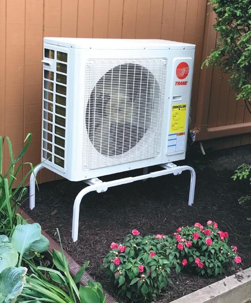
to the thermodynamic underlying “heat
    engines,” which are devices that extract        Figure 1-1
    energy from some higher-temperature
    material and convert that energy into
    a combination of mechanical work
    and lower-temperature heat. From a
    thermodynamic perspective, a heat                warm
    pump can be thought of as a heat engine          air to
    operating in reverse. It combines heat          building

    from a low-temperature source material

                                                                                                                            outside
                                                                                                                                           cold air

                                                                                                                   inside
    with mechanical work to produce heat
    at a higher temperature. Carnot, building                                  supply
                                                                                 air
    on the work of Kelvin, also developed                                      ducting
    a formula that sets the theoretical                                        blower
    performance limits for any heat pump.                                                           refrigerant

                                                          indoor air handler
                                                                                                      tubing

    Crude heat pumps were developed in
                                                                                                                              cool                           cool
    the early 1900s but remained little more                                                                                   air                            air
                                                                                                        return
    than science experiments at a time

                                                                                     filter
                                                                                                          air
    when fossil fuels, especially coal and                                                             ducting
    petroleum, were the dominant energy
    source for heating buildings.                                                             refrigerant-to-air                      air-to-air heat pump
                                                                          condensate
                                                                                               heat exchanger                              outdoor unit
                                                                             drain
    The first heat pumps to be mass
    produced were based on machines used
    for central air conditioning. The Carrier
    Corporation is widely recognized as one
                                                                                     Figure 1-2
    of the first companies to commercialize residential central
    cooling using vapor-compression refrigeration systems.
    During the 1950s, Carrier Corporation provided over 700
    early-generation central air-conditioning systems for one
    of the first large-scale housing developments in Levittown,
    Pennsylvania.

    Although often taken for granted today, the advent of
    central air conditioning at that time allowed scarcely
    populated areas in the southwestern U.S. to develop into

                                                                                                                                                                    Courtesy of Allied A/C & Heating
    major population centers. Some historians have even cited
    air conditioning as one of the most impactful technical
    accomplishments of the 20th century.

    Early-generation air-conditioning systems were only able
    to cool buildings, absorbing heat from interior spaces and
    dissipating it to outside air. The next technological hurdle
    was finding ways to reverse the direction of heat flow,
    and thus convert low-temperature heat in outside air into                       interior air handler using two copper refrigerant tubes. The
    higher-temperature heat to maintain comfort in buildings.                       compressor is located in the outdoor unit. The indoor unit
    This was the advent of air-to-air heat pumps.                                   contains a refrigerant-to-air heat exchanger and blower.

    The basic configuration of a “split system” air-to-air heat                     As is often the case with new technologies, early
    pump, operating in heating mode, is shown in Figure 1-1.                        experiences with air-to-air heat pumps were mixed. First
    The outside unit, often called the “condenser” because                          generation products experienced higher than acceptable
    of its origin in air-conditioning systems, connects to an                       compressor failure rates. In 1964, this reliability issue led

6
the U.S. Department of Defense to issue a ban on the use         Reversing valves made it practical to heat and cool homes
                        of heat pumps in military facilities due to the severity of      using air-to-air heat pumps. Sales of residential air-to-air
                        maintenance problems. Fossil fuel continued to be the            heat pumps grew rapidly during the 1970s. The primary
                        dominant energy source for heating buildings.                    markets were southern states with relatively mild winter
                                                                                         temperatures and a definite need for summer cooling. Air-
                        The OPEC oil embargo, which began in 1973, reinvigorated         to-air heat pumps became heavily promoted by southern
                        efforts to develop reliable electrically powered heat pumps      electric utilities, as well as by manufacturers such as
                        that could lessen dependence on petroleum-based                  Carrier, Westinghouse and General Electric.
                        heating fuels. Manufacturers of air-conditioning systems
                        worked on methods of reversing the direction of heat flow,       During the 1970s, the reliability of air-to-air heat pumps
                        and thus allow low-temperature heat in outside air to be         continually improved through revised compressor design,
                        raised to temperatures sufficient for heating buildings.         better lubrication details and techniques to reduce liquid
                                                                                         “slugging” of compressors. By 1975, the U.S. Department
                        One of the earliest attempts at creating a vapor-                of Defense lifted their previous ban on heat pumps in military
                        compression machine that could heat as well as cool              facilities. A surge of interest in heat pumps during 1976
                        simply reversed the direction of the entire air conditioner      lead to an annual sales growth rate of 96%. Manufacturers
                        within an opening in an exterior wall. Another used multiple     were having difficulty keeping up with demand. By 1978, it
                        dampers to change airflow directions.                            was estimated that air-to-air heat pumps were installed in
                                                                                         over 1.4 million U.S. homes.
                        Manufacturers eventually discovered that the refrigerant
                        flows used in vapor-compression air conditioners could           PERFORMANCE LIMITATIONS
                        be reversed using a combination of four hand-operated            Early generation air-to-air heat pumps could not operate
                        valves. In time, this approach was replaced by two valves        well at the low outdoor temperatures experienced in
                        operated by electrical solenoids. Further development led        the Northern U.S. and Canada. Many were limited to
                        to a single 4-port, electrically operated “reversing valve.”     minimum outdoor temperatures in the range of 15-20ºF.
                        This type of valve, which is discussed in more detail later in   If the outdoor temperature dropped below this limit, the
                        this issue, is now used in a wide variety of heat pumps that     heat pump would operate at grossly insufficient output or
                        provide heating and cooling.                                     simply turn off. The heating load would then be assumed
                                                                                         by electric resistance “strip heaters,” which are heating
                        Figure 1-3
                                                                                         elements mounted in the supply air plenum on the heat
                                                                                         pump’s interior unit, as shown in Figure 1-4.

                                                                                         Strip heat was usually activated by the second stage of
                                                                                         a 2-stage thermostat as room air temperature dropped
                                                                                         slightly below the desired setting. Although reliable as
                                                                                         a supplemental heat source, strip heat, like all electric-
                                                                                         resistance heating, is expensive to operate. Some early-
                                                                                         generation air-to-air heat pumps were also installed
                                                                                         along with gas-fired furnaces that would assume the full
                                                                                         heating load if the heat pump could not operate due to
                                                                                         low outdoor temperature or some other condition.

                                                                                         The inability to operate at the low outdoor air temperatures
                                                                                         experienced in many northern states, and much of
                                                                                         Canada, created a stigma that air-source heat pumps
                                                                                         were only suitable for heating in mild climates. This
                                                                                         limitation was one of the largest factors leading to the
                                                                                         emergence of geothermal heat pumps during the 1980s.
Courtesy of AD Cooper

                                                                                         Because water returning from earth loops, wells or large
                                                                                         open bodies of water was always above 32ºF, even
                                                                                         when outdoor air temperatures were extremely cold,
                                                                                         geothermal heat pumps could provide predictable heating
                                                                                         performance in northern climates. In milder climates,

                                                                                                                                                          7
Figure 1-4

                                          warm
                                          air to
                                         building

                                                                                       electric

                                                                                                                        outside
                                                                                      strip heat                                             cold air

                                                                                                             inside
                                                                                       auxiliary
                                                                                       heating

                                                                       blower
                                                                                              refrigerant
                                               indoor air handler

                                                                                                tubing

                                                                                                                          cool                             cool
                                                                                                    return                 air                              air
                                                                             filter

                                                                                                      air
                                                                                                   ducting

                                                                                        refrigerant-to-air                          air-to-air heat pump
                                                               condensate
                                                                                         heat exchanger                                  outdoor unit
                                                                  drain

    geothermal heat pumps also provided
    higher-efficiency cooling performance                           Figure 1-5
    compared to early-generation air-
    source heat pumps. The North
    American market for geothermal heat
                                                                                                                      refrigeration piping
    pumps has grown steady over the
    last 30 years, largely driven by the
    potential for high efficiency and thus
    lower operating cost.                                                                              indoor
                                                                                                       evaporator &
                                                                                                       air handler
    COLD CLIMATE AIR-SOURCE
    HEAT PUMPS
    As the market for geothermal heat
    pumps increased over the last 20
    years, so did efforts to improve
    the performance of air-source
    heat pumps. New refrigeration
    technologies such as enhanced
    vapor injection (EVI), variable-                                  air-cooled
                                                                      condenser
    speed “inverter” compressors, and
    electronic expansion valves, none
    of which were available for use
    in early-generation heat pumps,                Many “cold climate” air-to-air heat                                            one or more indoor air handlers using
    now allow modern air-source heat               pumps (a.k.a. “low ambient” air-                                               refrigeration piping. Figure 1-5 shows
    pumps to achieve significantly higher          source heat pumps) are currently                                               the concept for a ductless split air-
    thermal performance at cold outdoor            available as “ductless” split systems.                                         to-air heat pump system with two
    temperatures, in some cases as low             A single outdoor unit connects to                                              interior wall-mounted air handlers.
    as -22ºF.

8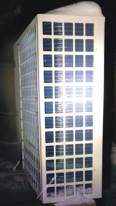
Figure 1-6                                                        MODERN AIR-TO-WATER HEAT PUMPS
                                                                  The same innovations that now make ductless air-to-air
                                                                  heat pumps viable in cold climate applications have been
                                                                  used to create air-to-water heat pumps. When operating
                                                                  in heating mode, these units absorb heat from outdoor
                                                                  air, concentrate that heat to increase its temperature, and
                                                                  transfer it to a stream of water or an antifreeze solution.
                                                                  The heated water can be used for a wide variety of loads
                                                                  such as hydronic space heating, domestic water heating
                                                                  or pool heating. Air-to-water heat pumps can also be
                                                                  reversed to extract heat from an interior stream of water
                                                                  and dissipate it to outside air. As such they can be used
                                                                  to supply several types of chilled-water cooling distribution
                                                                  systems. Modern air-to-water heat pumps provide an
                                                                  ideal combination of low ambient thermal performance
                                                                  along with the unsurpassed comfort and energy efficiency
                                                                  afforded by modern hydronics technology.

                                                                  One example of a modern air-to-water heat pump is shown
                                                                  in Figure 1-8.

                                                                  The remainder of this issue will discuss the details for
                                                                  applying modern air-to-water heat pumps in a variety of
                                                                  heating and cooling applications.
                                                                  Figure 1-8

Figure 1-7

An example of a typical outdoor unit for a modern air-to-air
heat pump is shown in Figure 1-6. One of the indoor air
handler units connected to this outdoor unit is shown in
Figure 1-7.

Although “ductless” split system heat pumps can provide
reasonably good thermal performance, they are limited
to space heating or cooling. They are also limited by the
compromises associated with forced air distribution.
These include drafts, dispersal of dust and allergens,
potential for clogged air filters, cool air collecting at floor
level as warm air rises to ceiling level, possible aggravation
of respiratory illnesses and objectionable interior noise.

                                                                                                                                  9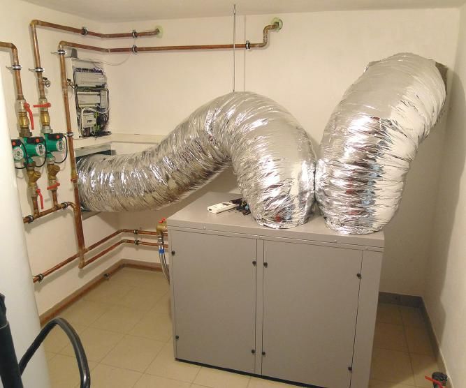
HEAT PUMP OPERATING FUNDAMENTALS
The refrigeration cycle is the basis of
operation of all vapor-compression Figure 2-2
electrical
heat pumps. During this cycle, a power input
chemical compound called the (Q2) higher
low
refrigerant circulates around a compressor temperature
temperature
closed piping loop passing through heat heat
all major components of the heat absorbed dissipated
pump. These major components are from source to load
(Q1) (Q3)
evaporator
named based on how they affect the
condenser
refrigerant passing through them.
They are as follows:
• Evaporator
• Compressor
thermal
• Condenser
expansion
• Thermal expansion valve (TXV)
valve
(TXV)
The basic arrangement of these
components to form a complete
refrigeration circuit are shown in Q1 Q2 Q3
Figure 2-1.
To describe how this cycle works, a
quantity of refrigerant will be followed
through the complete cycle.
temperature source media into the above its saturation temperature
lower-temperature refrigerant. As (e.g., where it vaporizes) is called
The cycle begins at station (1)
the refrigerant absorbs this heat, superheat, which also comes from
as cold liquid refrigerant within
it changes from a liquid to a vapor the source media.
the evaporator. At this point, the
(e.g., it evaporates). The vaporized
refrigerant is colder than the source
refrigerant continues to absorb heat This vaporized refrigerant then flows on
media (e.g., air or water) passing
until it is slightly warmer than the to the compressor at station (2). Here
across the evaporator. Because
temperature at which it evaporates. a reciprocating piston or an orbiting
of this temperature difference,
The additional heat required to raise scroll driven by an electric motor
heat moves from the higher-
the temperature of the refrigerant compresses the vaporized refrigerant.
This causes a large increase in both
pressure and temperature. The
Figure 2-1 refrigerant flow electrical energy used to operate the
medium temperature compressor high temperature
compressor is also converted to heat
low pressure high pressure and added to the refrigerant. The
VAPOR VAPOR temperature of the refrigerant gas
leaving the compressor is usually in
the range of 120º to 170ºF depending
on the operating conditions.
2
evaporator
condenser
SOURCE SINK
media 1 3 media The hot refrigerant gas then flows into
the condenser at station (3). Here it
transfers heat to a stream of water or
4 air (e.g., the sink media) that carries
the heat away to the load. As it gives
low temperature thermal medium temperature
low pressure high pressure up heat, the refrigerant changes from
expansion
LIQUID LIQUID a high-pressure, high-temperature
valve
vapor into a high-pressure, somewhat
(TXV)
cooler liquid (e.g., it condenses).
10The high-pressure liquid refrigerant Figure 2-3 As a dedicated heating device, the
then flows through the thermal evaporator side of the heat pump will
expansion valve at station (4), where its always gather low-temperature heat
pressure is greatly reduced. The drop in from some source where that heat
pressure causes a corresponding drop is freely available and abundant. The
in temperature, restoring the refrigerant condenser side will always deliver
to the same condition it was in when higher-temperature heat to the load.
the cycle began. The refrigerant is
now ready to repeat the cycle. One example would be a heat pump
that always delivers energy for space
The refrigeration cycle remains in heating a building. Another would be a
continuous operation whenever the heat pump that always delivers energy
compressor is running. This cycle is to heat domestic water. Still another
not unique to heat pumps. It is used would be a heat pump that always
in refrigerators, freezers, room air delivers heat to a swimming pool.
conditioners, dehumidifiers, water
coolers, vending machines and other
heat-moving machines. Figure 2-4 compressor!
discharge
Figure 2-2 shows the three primary
energy flows involved in the capillary tubing
refrigeration cycle. The first energy
input is low-temperature heat low!
pressure!
slide
absorbed from the source media gas high pressure
refrigerant!
into the refrigerant at the evaporator. vapor
The second energy input is electrical
energy flowing into the compressor
whenever it is operating. The third
energy flow is the heat output into
the sink media at the condenser.
from! compressor! to high!
low temp. HX suction temp. HX
The first law of thermodynamics
dictates that, under steady state capillary tubing
off
conditions, the total energy input rate (a) pilot!
solenoid!
to the heat pump must equal the total valve
compressor!
energy output rate. Thus, the sum of discharge
the low-temperature heat absorption
rate into the refrigerant at the
evaporator, plus the rate of electrical capillary tubing
energy input to the compressor, must
equal the rate of energy dissipation slide low!
pressure!
from the refrigerant at the condenser. high pressure gas
refrigerant!
This is depicted by the arrows in vapor
Figure 2-2.
NON-REVERSIBLE VS. REVERSIBLE
HEAT PUMPS
Heat pumps always move heat from
to high! compressor! from!
a lower-temperature source media to temp. HX suction low temp. HX
a higher-temperature “sink” media.
The basic non-reversible heat pump capillary tubing
described in Figures 2-1 and 2-2 (b) pilot! 24 VAC
solenoid!
can be used as a dedicated heating valve
device or a dedicated cooling device.
11When the heat pump needs to
Figure 2-5 operate in cooling mode, the pilot
compressor
solenoid valve is energized by
a 24 VAC electrical signal. This
reversing allows the refrigerant pressure to
HEATING valve
immediately move the slide within
MODE the reversing valve to the opposite
low higher end of its chamber. Hot gas leaving
temperature temperature
heat
the compressor is now routed to the
heat
absorbed dissipated heat pump’s other heat exchanger
evaporator
condenser
(e.g., what was the evaporator now
thermal
expansion
becomes the condenser.) This is
valve illustrated in Figure 2-4b.
(TXV)
Figure 2-5 shows where a reversing
compressor
valve is installed in an air-to-water
heat pump.
reversing The reversing valve effectively “swaps”
COOLING valve
the functions of the heat pump’s two
MODE heat exchangers. The heat exchanger
higher that serves as the evaporator in
temperature the heating mode serves as the
heat low
dissipated temperature
condenser in the cooling mode.
evaporator
condenser
heat Similarly, the other heat exchanger
thermal
absorbed that served as the condenser in the
expansion
valve heating mode acts as the evaporator
(TXV) in the cooling mode.
The most common configuration
for a reversible heat pump is one
As a dedicated cooling device, the in cold weather can also cool that in which two thermal expansion
evaporator side of a non-reversible building during warm weather. valves are used in combination
heat pump always absorbs heat from with two check valves. One thermal
a media that is intended to be cooled. Reversible heat pumps contain an expansion valve functions during
Examples would be heat extraction electrically operated device called a the heating mode, while the other
from a building during warm weather, reversing valve. Figure 2-3 shows an functions during the cooling mode.
or heat extraction from water that example of a modern reversing valve. Some heat pumps also use a
will eventually be converted into ice. single electronically controlled “bi-
The condenser side of such a heat The type of reversing valve used directional” thermal expansion
pump will always dissipate heat to in most heat pumps contains a valve. For simplicity, the heat pump
some media that can absorb it (e.g., slide mechanism that is moved by refrigeration piping diagrams shown
outside air, ground water or soil). refrigerant pressure. The direction assume a single bi-directional
of movement is controlled by a thermal expansion valve.
There are several applications where small “pilot” solenoid valve. When
non-reversible heat pumps can be the heat pump is in heating mode,
HEATING MODE
applied. However, one of the most the magnetic coil of pilot solenoid
unique benefits of modern heat valve is not energized. This allows THERMAL PERFORMANCE
pumps is that the refrigerant flow can the high-pressure refrigerant leaving In the heating mode, there are two
be reversed to quickly convert the the compressor to position the slide indices used to quantify heat pump
heat pump from a heating device to a within the reversing valve so hot performance:
cooling device. Such heat pumps are refrigerant gas from the compressor
said to be “reversible.” A reversible goes to the condenser, as shown in a. Heating capacity
heat pump that heats a building Figure 2-4a. b. Coefficient of performance (COP)
122 to 3 gpm per 12,000 Btu/hr of rated heating capacity are
Figure 2-6 generally recommended.
131 ºF leaving water temp.
113 ºF leaving water temp.
The coefficient of performance (COP) of a heat pump is
95 ºF leaving water temp.
a number that indicates the ratio of the beneficial heat
70000
output from the heat pump, divided by the electrical power
input required to operate the heat pump. The higher the
60000
heating capacity (Btu/hr)
COP, the greater its rate of heat output per unit of electrical
input power.
50000
Formula 2-1 shows this relationship in mathematical form.
40000 The factor 3.413 in this ratio converts watts into Btu/hr.
This makes COP a unitless number.
30000
Formula 2-1
20000
10000
0 COP can also be visualized Tsink as the ratio of the heat output
COPCarnot =
-10 0 10 20 30 40 50 60 70 arrow divided by the (Tsink electrical
− Tsource ) power input arrow, as
outdoor temperature (ºF) shown in Figure 2-7.
Another way toQthink of COP
cooling is the
capacity number of units of
(Btu/hr)
Heating capacity is the rate at which the heat pump delivers EER= c =
heat output energywe the heat pump delivers
electrical input wattage per unit of
heat to the load. As such, it is similar to the heating capacity electrical input energy. Thus, if a heat pump operates at a
of a boiler. However, the heating capacity of any heat pump COP of 4.1, it provides 4.1 units of heat output energy per
is very dependent on its operating conditions, specifically equivalent unit of electrical 48,000Btu
input energy.
/ hr
the temperature of the source media and the temperature COPHPonly = = 3.35
Btu / hr
of the sink media. The greater the temperature difference ⎡⎣ 4200 ⎤⎦ watt as
COP can also be considered × 3.413
a way to compare the
watt
between the source media and the sink media, the lower thermal advantage of a heat pump to that of an electric
the heat pump’s heating capacity. Figure 2-6 shows how
heating capacity of a specific air-to-
water heat pump varies as a function of
Figure 2-7 electrical
COPnet =
48,000Btu / hr
= 2.92
outdoor air temperature and the water Btu / hr
temperature leaving its condenser.
power input ( )
⎡⎣ 2 × 220 + 4200 + 180 ⎤⎦ watt × 3.413
low ! (Q2) higherwatt
!
compressor temperature!
A heat pump’s heating capacity also temperature!
heat! heat!
depends on the flow rate of the source dissipated!
absorbed! 48,000Btu / hr
and sink media through the evaporator COPHPonly = = 2.56
from source! Btu / hr to load!
and condenser. The higher these flow ⎡⎣5500 ⎤⎦ watt × 3.413 (Q3)
evaporator
(Q1)
condenser
watt
rates are, the greater the heating capacity
will be. This is the result of increased
convection heat transfer at higher flow
velocities. However, the gains in heating 48,000Btu / hr
COPnet = = 2.48
capacity are not proportional to the Btu / hr
⎡⎣5500 + 180 ⎤⎦ watt × 3.413
increase in flow rate. Heating capacity watt
increases incrementally at high flow
rates. In some cases, the gains in heating
⎡ 1 1 ⎤
capacity do not justify the significantly
COP =
Es = E R ⎢Q3 − ⎥
higher electrical power input to larger ⎣ COPL COPH ⎦
circulators, higher speed operation of
variable-speed circulators, or higher fan Q2
speeds. Water flow rates in the range of ⎡ 1 1 ⎤ ⎡ 1 1 ⎤
Es = E R ⎢ − ⎥ = 39.9 ⎢ − ⎥ = 4.22 MMBtu / season
⎣ COPL
COPH ⎦ ⎣ 2.5 3.4 ⎦
13Figure 2-8 Figure 2-9
130 ºF leaving water temp.
120 ºF leaving water temp.
sink!
110 ºF leaving water temp.
media 4
3.5
3
2.5
temperature lift
COP
2
1.5
1
0.5
source! 0
media -10 0 10 20 30 40 50
outdoor temperature (ºF)
resistance heating device that provides the same heat The theoretical maximum COP for any heat pump was
output. For example, if an electric resistance space established by nineteenth century scientist Sadi Carnot
heater is 100% efficient, then by comparison, a heat and is appropriately called the Carnot COP. It is based on
pump with a COP of 4.1 would be 410% efficient. the absolute temperatures of the source media and sink
Some would argue that no heat source can have an media and is given in Formula 2-2.
efficiency greater than 100%. This is true for any heat
source that simply converts a fuel into heat. However, Formula 2-2
much of the heat released by a heat pump is heat that Tsink
was moved instead of created through combustion or COPCarnot =
direct conversion of electrical energy to heat. As such,
(Tsink − Tsource )
its beneficial effect is equivalent to a heat source that
would have an efficiency much higher than 100%. COPCarnot = Carnot COP (the maximum possible COP of
any heat pump)
Qc cooling capacity (Btu/hr)
The COP of all heat pumps is highly dependent on Tsink = absoluteEER= = of the sink media to which
temperature
operating conditions. This includes the temperature of heat is delivered (ºR) we electrical input wattage
the source media, as well as the media to which the heat Tsource = absolute temperature of the source media from
pump dissipates heat. The closer the temperature of the which heat is extracted (ºR)
source media is to the temperature of the sink media, the ºR = ºF + 458º
higher the heat pump’s COP. 48,000Btu / hr
This Carnot COP COP
is based =
HPonly on a hypothetical heat pump
= 3.35
Btu / hr
One can visualize the difference between the source and that has no mechanical energy ⎡⎣ 4200 ⎤⎦ watt
losses due× 3.413
to friction or
sink temperatures as the “temperature lift” the heat pump electrical losses due to resistance. It is also based watt
on
must provide, as shown in Figure 2-8. “infinitely sized” source and sink that remain at exactly the
same temperatures as they give up and absorb heat. No
The smaller the lift, the higher the heat pump’s COP. real heat pump operates under such idealized conditions,
and thus no real heat pump ever attains the Carnot COP.
48,000Btu / hr
COPnet =
Btu
⎡⎣( 2 × 220 ) + 4200 + 180 ⎤⎦ watt × 3.413
w
14vapor from the air stream. However, because air-to-water
Figure 2-10 and water-to-water heat pumps both deliver a stream
leaving chilled water temp = 59 ºF of cool water as their output, there is only one rating for
leaving chilled water temp = 55 ºF cooling capacity, which in North American is usually
leaving chilled water temp = 50 ºF expressed in Btu/hr.
leaving chilled water temp = 45 ºF
70000 Cooling capacity is significantly influenced by the
temperature of the air entering the heat pump’s condenser,
65000 and the temperature of water entering the heat pump’s
evaporator. Cooling capacity increases when the
Cooling capacity (Btu/hr)
60000 temperature of the water delivering unwanted heat to the
heat pump’s evaporator increases. Cooling capacity also
55000 increases when the temperature of the air absorbing heat
from the heat pump’s condenser decreases. So, as was
50000 true for both heating capacity, and COP, the closer the
source temperature is to the sink temperature, the higher
45000 the cooling capacity of the heat pump. This is shown, for a
specific heat pump, in Figure 2-10.
40000
60 65 70 75 80 85 90 95 100 105 ENERGY EFFICIENCY RATIO
Oudoor air temperature (ºF) In North America, the common way of expressing the
instantaneous cooling efficiency of a heat pump is called
Energy Efficiency T (EER), which can be calculated
COPCarnot =Ratio sink
The COPs of currently available heat pumps, even when using Formula 2-3. (Tsink − Tsource )
operated under very favorable conditions, is substantially
lower than the Carnot COP. Still, the Carnot COP serves as Formula 2-3
a way to compare the performance of evolving heat pump
technology to a theoretical limit. It also demonstrates the Qc cooling capacity (Btu/hr)
EER= =
inverse relationship between the “temperature lift” of a heat we electrical input wattage
pump and COP.
The COP of air-to-water heat pumps decreases as the Figure 2-11
48,000Btu hr = 59 ºF
water/temp
outside air temperature decreases. It also decreases as COPHPonlyleaving
= chilled = 3.35
leaving chilled water
Btu / hr
temp = 55 ºF
the temperature of the water leaving the heat pump’s ⎣⎡ 4200 ⎦⎤ watt × 3.413 watt
condenser increases. Figure 2-9 shows a typical leaving chilled water temp = 50 ºF
relationship between COP versus outdoor temperature leaving chilled water temp = 45 ºF
and the water temperature leaving the condenser for a
14
Energy Efficiency Ratio (EER) (Btu/hr/watt)
modern “low ambient” air-to-water heat pump.
13 48,000Btu / hr
COPnet = = 2.92
COOLING MODE THERMAL PERFORMANCE ⎡⎣( 2 × 220 ) + 4200 + 180 ⎤⎦ watt × 3.413
Btu / hr
12
In the cooling mode, the two indices used to quantify the watt
performance of air-to-water heat pumps are: 11
a. Cooling capacity 10
b. Energy Efficiency Ratio (EER) 48,000Btu / hr
9 COPHPonly = = 2.56
Btu / hr
⎡⎣5500 ⎤⎦ watt × 3.413
For air-to-air and water-to-air heat pumps, both of which 8 watt
use forced-air delivery systems, cooling capacity is divided
into two parts: sensible cooling capacity and latent cooling 7
capacity. Sensible cooling capacity is based on the 6
temperature drop of the interior air stream passing through 65 70= 75 80 85
60 COP 90 95 / hr
48,000Btu 100 105 = 2.48
the heat pump’s evaporator coil. Latent cooling capacity Outdoor air temperature (ºF) Btu / hr
net
⎡⎣5500 + 180 ⎤⎦ watt × 3.413
is based on the ability of the interior coil to remove water watt
⎡ 1 1 ⎤
Es = E R ⎢ − ⎥
⎣ COPL COPH ⎦ 15hr. The tonnage of a heat pump has nothing to do with
Figure 2-12 the heat pump’s weight. The unit of “ton” originated during
the transition from stored natural ice as a means of cooling
evaporator
to mechanical refrigeration. It represents the average heat
outside outside transfer rate associated with melting one ton of ice over a
air fan air 24-hour period.
A description of a heat pump heating or cooling capacity
based on tons is usually a nominal rating at some specific
compressor set of operating conditions. Thus, a “3-ton” rated heat
pump could yield a heat output rate significantly higher than
3 tons when operated under more favorable conditions,
condensor
and significantly less than 3 tons when operated under
water out unfavorable conditions.
ENHANCED VAPOR INJECTION
One of the developments that has significantly improved
water in
(main) TXV the ability of air-source heat pumps to operate at low
thermal outside air temperature is called enhanced vapor injection
expansion (EVI). This refers to a modified refrigeration circuit that
valve lowers the temperature of liquid refrigerant entering the
outdoor evaporator when the heat pump is operating in
heating mode. The lower the liquid refrigerant temperature
Where:
entering the evaporator, the lower the air temperature at
EER = Energy Efficiency Ratio
which the heat pump can operate. EVI also increases
Qc = cooling capacity (Btu/hr)
the refrigerant mass flow through the compressor, which
We = electrical power input to heat pump (watts)
helps in maintaining heating capacity at low outdoor air
temperatures.
The higher the EER of a heat pump, the lower the electrical
power required to produce a given rate of cooling.
To understand EVI, it is helpful to consider a basic
refrigeration circuit of a heating-only air-to-water heat
Like COP, the EER of an air-to-water heat pump depends
system, as shown in Figure 2-12.
on the source and sink temperature. The warmer the
source media temperature is compared to the sink media
The temperature and liquid/vapor proportions of the
temperature, the higher the heat pump’s EER. Figure 2-11
refrigerant leaving the condenser, in part, determine the
shows how the outdoor air temperature and leaving chilled-
extent to which the thermal expansion valve can lower the
water temperature affect the EER of a specific air-to-water
refrigerant temperature entering the outdoor evaporator.
heat pump.
This, in turn, limits the low ambient heating capacity and
COP of the heat pump.
To maximize EER, designers of chilled-water cooling
systems using either air-to-water or water-to-water heat
Figure 2-13 shows how the basic refrigeration circuit of
pumps should use the highest possible chilled-water
Figure 2-12 is modified to allow EVI functionality.
temperature that still allows adequate dehumidification. EER
is also slightly influenced by flow rates. Higher flow rates of
EVI works by routing the refrigerant leaving the condenser
either the source media or the sink media produce small
through an intermediate heat exchanger called a “sub-
increases in EER. This is the result of increased convection
cooler.” A portion of the refrigerant passes directly through
on both the air-side and water-side heat exchangers.
one side of the sub-cooler. The other portion passes
through an electronic expansion valve that lowers the
WHAT DOES “TONS” MEAN? refrigerant’s pressure and temperature prior to flowing
In North America, the heating and cooling capacity of a through the other side of the sub-cooler. This portion of
heat pump is often stated in “tons.” In this context, a ton the refrigerant evaporates in the sub-cooler, absorbing
describes a rate of heat flow. More specifically, 1 ton equals heat from the other portion. This reduces the temperature
12,000 Btu/hr. Thus, a “4-ton” heat pump implies a nominal of the liquid entering the thermal expansion valve, and thus,
heating or cooling capacity of 4 x 12,000 or 48,000 Btu/ the temperature entering the evaporator. The lower the
16refrigerant temperature entering
Figure 2-13 the evaporator, the better it can
evaporator
absorb heat from cold outside air.
outside outside The vapor formed as part of
air fan air the refrigerant expands within
the sub-cooler is at a pressure
higher than that at the suction
vapor injection port port of the compressor. This
EVI enabled
medium-pressure vapor is routed
compressor
electronic expansion back into the refrigeration cycle
valve using a specially designed scroll
condensor compressor with a medium-
water out
pressure vapor injection port.
The medium-pressure refrigerant
vapor enters at a specific location
water in within the scroll set. That location
prevents the injected vapor from
(main) TXV refrigerant
flowing toward the low-pressure
thermal "sub-cooler" solenoid side of the scroll set. This effectively
expansion valve
sub cooled increases the compression ratio
valve
liquid refrigerant beyond the mechanical ability
of the compressor alone. Figure
2-14 compares the refrigerant
temperature operating range of
a typical 2-stage scroll compressor versus a scroll
Figure 2-14 compressor using EVI. Notice that the vapor-injected
operating range of a typical compressor can achieve much lower refrigerant
evaporating temperatures. The lower the refrigerant
2-stage scroll compressor
evaporating temperature, the lower the outdoor
operating range of a vapor air temperature from which useable heat can be
injection compressor extracted.
One characteristic of air-to-water heat pumps using
140
refrigerant condensing temperature (ºF)
EVI refrigeration systems is an increase in heating
capacity as the temperature of the water leaving the
120 condenser increases. This is shown in Figure 2-15.
100 This characteristic is counterintuitive because it
is opposite from the decrease in heating capacity
80 of non-EVI refrigeration systems as the water
temperature leaving the condenser increases.
60 However, as is true with non-EVI refrigeration
circuits, there is a significant drop in COP as the
water temperature leaving the condenser increases.
40
Since the principal goal is to keep the heat pump’s
COP as high as possible, it’s always best to operate
20 the hydronic system at the lowest water temperature
that maintains comfort in the heated space.
0
-60 -40 -20 0 20 40 60 Many contemporary air-to-water heat pumps,
especially those intended for use in cold climates,
refrigerant evaporating temperature (ºF)
now use EVI refrigeration systems. These heat
pumps are sometimes called “cold climate” or “low
ambient” heat pumps to emphasize their suitability
17Figure 2-15 DEFROSTING
All air-source heat pumps (e.g., air-to-air and air-to-water)
130 ºF leaving water temp.
used in climates where outdoor temperatures drop below a
120 ºF leaving water temp. nominal 50ºF will, at times, accumulate frost on the outdoor
110 ºF leaving water temp. air-to-refrigerant heat exchanger, which operates as the
70000 evaporator during heating mode. The rate at which frost
accumulates depends on several factors, such as relative
65000 humidity, concurrent precipitation and the evaporating
heating capacity (Btu/hr)
temperature of the refrigerant. Figure 2-16a shows an
60000 example of a heavily frosted evaporator coil on a monobloc
air-to-water heat pump.
55000
50000 Figure 2-16b shows this evaporator partially defrosted.
Figure 2-16c shows the fully defrosted evaporator, with
45000 melt water draining from the bottom of the enclosure.
40000 As frost builds on the evaporator, airflow is reduced,
which reduces the ability of the refrigerant to absorb
35000 heat from outside air. To restore heating performance, it’s
necessary to melt the frost off the evaporator. This is done
30000
automatically by temporarily switching the refrigerant
-10 0 10 20 30 40 50 flow direction using the reversing valve. This forces hot
outdoor temperature (ºF) refrigerant gas through the evaporator, which rapidly
melts the frost. In effect, the heat pump is temporarily
130 ºF leaving water temp. switched to cooling mode operation while defrosting.
120 ºF leaving water temp.
On most air-to-air heat pumps, the heat needed to
110 ºF leaving water temp. melt frost comes from indoor air. This often results in
4
cool air being discharged from the indoor portion of the
3.5 heat pump. Although a typical defrost cycle may only
last a few minutes, cool air discharging from the indoor
3 portion of an air-to-air heat pump during cold weather is
arguably a significant compromise in comfort.
2.5
However, most air-to-water heat pumps are connected
COP
2 to a buffer tank. Heat for defrosting comes from this
tank. Even in systems without buffer tanks, the attached
1.5 hydronic distribution system has much greater thermal
mass relative to air, and thus, any deviation in the
1
temperature of the distribution system during defrost is
0.5 small and of short duration. In most systems, there is no
detectable effect on indoor comfort. This is a significant
0 advantage of air-to-water over air-to-air heat pumps.
-10 0 10 20 30 40 50
outdoor temperature (ºF) Heat pump manufacturers offer different methods for
defrosting. Sometimes defrosting occurs on a fixed
elapsed time basis. It may also be “demand-controlled”
defrost, which is usually based on low refrigerant
for use in cold locations. Many of these heat pumps are pressure at the suction side of the compressor. Some
capable of operating with reasonable performance at sub modern air-to-water heat pumps also take the ambient
0ºF air temperatures. air temperature into account when determining the need
for defrosting. The goal is to clear the evaporator of frost
with minimum required heat.
18You can also read