Air-to-Water Heat Pumps for Low Energy & Net Zero Houses - Home ...
←
→
Page content transcription
If your browser does not render page correctly, please read the page content below
Air-to-Water Heat Pumps for Low Energy & Net Zero Houses
presented at:

February 14, 2018
8:30-10:00

presented by:
John Siegenthaler, P.E.
Appropriate Designs
Holland Patent, NY
www.hydronicpros.com
 © Copyright 2018, J. Siegenthaler, all rights reserved. The contents of this file shall not be copied or transmitted in any form without written permission of the author. All diagrams shown in this file
 on conceptual and not intended as fully detailed installation drawings. No warranty is made as the the suitability of any drawings or data for a particular application.
• Most North America heating professionals are familiar with ductless mini-split heat pumps.

• Most are also familiar with geothermal heat pumps

• Very few are currently familiar with air-to-water heat pumps.

      Ductless mini-split
         heat pump
                                                                                               ?
   www.johnstone.com

                                                                           air-to-water heat pump
                                 geothermal heat pump
                                    airconditioning-repair-nashville.com
This is not the case in other global markets…
Global air-to-water heat pump market:
According to JARN (Aug 2015)

2014 global market: 1,745,000 air to water heat pumps sold

Japanese manufacturers [Daikin, Mitsubishi, Fujitsu, Hitachi, Samsung, LG, Toshiba]
German manufacturers [Dimplex, Wolf, Viessmanm, Bosch,Vaillant]
Canadian manufacturers [ThermAtlantic, Nordic]

2014 China market : 987,000 units (12% increase over 2013)

2014 European market: 232,000 units (5% increase over 2013)
#1 France, #2 Germany, #3 UK
Still only about 2% of heat sources sold in Europe

Due to low gas and oil prices, AWHP are subsided in Europe based on CO2 reduction
targets, rather than energy efficiency.

Many current models use inverter drive variable speed compressors for capacity
control. Some use EVI (enhanced vapor injection) compressors.
So what is an air-to-water heat pump?
air-to-water heat pump air-to-water heat pump
(in heating mode) (in cooling mode)
OUTSIDE
OUTSIDE
INSIDE
hot gaseous refrigerant
INSIDE
liquid refrigerant condenses to liquid
changes to vapor releasing heat
absorbing heat
hot
cold fan outside
outside air
condenser
fan warm
air
evaporator
cool outside
outside air
air
condensate
hot gas drain
cool gas cool gas
hot gas hot cold fluid
fluid hot gas
evaporator
liquid refrigerant
condenser
warm
heat to RV comp. heat
RV comp. fluid building from
TXV
cool fluid circulator building
circulator
TXV hot gas condenses liquid refrigerant
to liquid releasing vaporizes absorbing
heat heat
liquid refrigerant
liquid & gaseous refrigerant liquid & gaseous refrigerant
In heating mode: The heat pump extracts low temperature heat
from outside air, and transfers it to a fluid stream (water or water &
antifreeze) to be used by a hydronic distribution system.
In cooling mode: The heat pump extracts low temperature heat from
a fluid stream (chilling it), and dissipates that heat to outside air.
Why hydronics vs. forced air?
Water is vastly superior to air for conveying heat

            this cut would destroy the load-carrying
            ability of the floor joists

                                                                      A given volume of water can
                                                                      absorb almost 3500 times as
                                                                      much heat as the same
                                                       2 x 12 joist

                                                                      volume of air, when both
                                                                      undergo the same
                          14" x 8" duct
                                                                      temperature change
            3/4" tube
Self-contained air-to-water heat pumps

                                        OUTSIDE

                                                  INSIDE
                                                           warmer climate application
                                                           (water in outside unit)

                                        OUTSIDE

                                                  INSIDE
           image courtesy of SpacePak

• Heating + cooling + DHW                                  colder climate application
• Pre-charged refrigeration system                         (antifreeze in outside unit)
• some are 2-stage for better load                                  antifreeze!
                                                                    protected!
matching                                                              circuit
• No interior space required

                                                                                  to / from!
• No interior noise

                                                                                     load
                                                                    heat!
                                                                 exchanger
Self-contained air-to-water heat pumps
Split system air-to-water heat pump
                                      Heating mode:
                                      1. condenser
                                      2. circulator
                                      3. expansion tank
                                      4. aux element
                                      5. controls

                                      Cooling mode:
                                                                                 indoor
                                      1. evaporator
                                                                                   unit
                                      2. circulator

                                                             OUTSIDE
                                      3. expansion tank

                                                                       INSIDE
                                      4. controls

                        Indoor unit
                                              outdoor unit

 Outdoor unit
  Heating mode:
  1. compressor
  2. evaporator
  3. expansion device

  Cooling mode:
  1. compressor                                                           refrigerant
  2. condenser                                                              lineset
  3. expansion device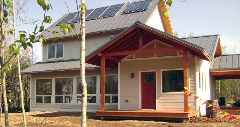
Split system air-to-water heat pump
European split system air-to-water heat pump supplying
heating and domestic hot water

                                      -4 ºF outside, 113 ºF leaving water temperature

www.NIBE.eu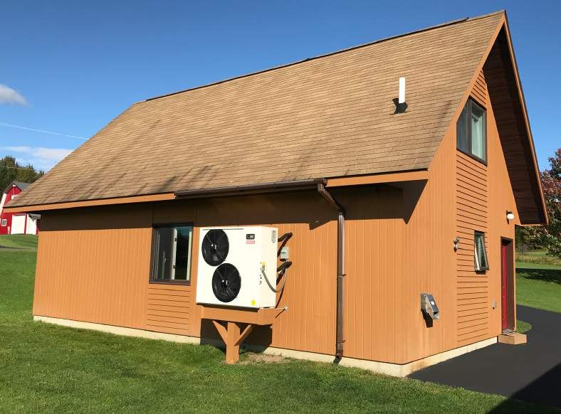
It’s not just about matching BTU delivery to load…
It’s about providing COMFORT
Ductless mini-split heat pumps rely on forced air
delivery.

While generally acceptable for cooling, forced air
delivery doesn’t provide optimal comfort for
heating.

                                                        www.amazon.com
• There will be some temperature stratification from
floor to ceiling.

• Mini-splits blow cool air into spaces while
defrosting outdoor unit.

• Cold floors are a common complaint with forced
air heating.

• High wall cassettes do little to counteract natural
downdraft from large window surfaces.

• Forced air heating may aggravate allergies or
other respiratory symptoms.

• There will be some sound from forced air terminal
units. Properly designed radiant floor, wall, and
ceiling panels can operate with virtually no
detectible sound.
Why is the “net zero” housing market defaulting to
mini-split heat pumps rather than hydronics?
source: Revision Energy
Training programs for “net zero”
houses often promote mini-split
heat pumps as the only
necessary heating & cooling
system.
They often discourage the
“complication” and cost
of hydronic systems.
historicshed.comBased on this - who can blame them ??
Common suggestion for net zero houses….
Install a ductless mini-split air-to-air heat pump,
with 1 or 2 indoor wall cassettes, and leave the        source: Revision Energy

interior doors open for heat distribution.
from a green building website blog…

“Leave bedroom doors open during the day
If you want to heat your house with a ductless
minisplit located in a living room or hallway, you’ll
need to leave your bedroom doors open during the
day. When the bedroom doors are closed at night,
bedroom temperatures may drop 5 F° between
bedtime and morning.”

“If family members don’t want to abide by this
approach, or don’t want to accept occasional low
bedroom temperatures during the winter, then
supplemental electric resistance heaters should be
installed in the bedrooms.”

The COPs of cold climate ductless mini-
split heat pumps at sub-0ºF ambient
conditions is seldom discussed.

Maintaining heating capacity at sub-0ºF
conditions doesn’t imply that COP is being
maintained.
                                                                                  historicshed.com
What happens to the COP of ductless mini splits at low ambient air temperatures? Site 1 : COP = 1.1 at 0 ºF Site 4 : COP = 1.8 at 0 ºF
Low ambient air-to-water heat pump yields good performance at low outdoor temperatures:

At ambient = 0 ºF, leaving fluid = 120 ºF, COP =2.04
Low ambient air-to-water heat pump performance
                                                           COP = 2.04 at 0 ºF
                                                           ambient and 120 ºF
                                                           leaving water temperature.

                                                           Heat pump heat output:
                                                           40,500 Btu/hr
                                                           Heat pump power:
                                                           5817 watts

                                       Btu
                                                           Heat pump circulator:
                             40,500
  COPHP+circulator   =                 hr         = 1.96   power: 200 watts
                                   ⎛       Btu ⎞
                                      3413
                                   ⎜       hr ⎟
                       ( 6.042kw ) ⎜                       Distribution circulator
                                         kw ⎟
                                   ⎜⎝          ⎟⎠
                                                           power: 25 watts
Higher than the measured COP of
several ductless mini split heat pumps                     Total power to system:
@ 0 ºF ambient.                                            6042 watts
Ductless mini-split heat pumps provide heating & cooling
historicshed.com
An air-to-water heat pump has
the potential to provide:
• Room-by-room zoning
• Radiant & convective heat delivery
• Zoned cooling (air & radiant delivery)
• Domestic water heating
• Pool heating in summer
• Higher distribution efficiency
• Fewer (if any) interior
refrigerant piping connectionsSeveral trends suggest that a growing market will emerge for air-to-water heat pumps. Here are some key indicators: 1. Growing interest in Net Zero houses: The typical net zero house has a very low loss thermal envelop, and a sizable solar photovoltaic array on the roof. Net metering laws - where they exist - allow owners of photovoltaic systems to sell surplus electrical power back to the utility at full retail rate. Thus, surplus kilowatt hours produced on a sunny summer day Source: Zerohomes.org could conceivably be “parked” on the electrical grid, and reclaimed to run a heat pump on a cold winter night with no technical or economic penalty. Space heat + DHW loads are so small it doesn't pay to put a gas meter on these houses. AWHP could provide heating, cooling, & DHW
Net Zero house in Seattle
                            Source: www.tclegendhomes.com
SPECS
 • 2,426 Square feet
 • 4 Bedrooms
 • 2.5 Baths
 • Radiant heat
 • Air-to-water heat pump
 • SIP construction
• 9.5 KW PV system
What are the advantages of using hydronic heating in these houses?
• Superior comfort: Radiant panel heating is better match to human physiological
comfort needs. It’s not just about pushing Btus into a space to match heat loss.
• Simple room-by-room (“wireless”) zoning is possible with many heat emitter options.
Don’t have to leave all doors open for internal heat balancing. A limitation of single point heat/cool
delivery such as wall cassette.
• Very high distribution efficiency
(A single ECM circulator operating on 10 to 40 watts supplies all heating distribution)
• Non-invasive installation of small tubing (3/8” & 1/2” PEX, PERT, or PEX-AL-PEX)
(Installing this tubing is like pulling electrical cable)
• Easily adapted to renewable
heat sources) (solar thermal,
hydronic heat pump, biomass)
• In many cases a single heat
source can supply heating and
DHW (fewer burners, less vents, less
fuel piping)
• Water-based thermal storage is
easily adapted to “time-of-use”
Electric rate structures.
source: Wagner Zaun ArchitectureWhat is distribution DISTRIBUTION EFFICIENCY?
desired OUTPUT quantity
Efficiency =
necessary INPUT quantity
Distribution efficiency for a space heating system.
rate of heat delivery
distribution efficiency=
rate of energy use by distribution equipment
Consider a system that delivers 120,000 Btu/hr at design load conditions using
four circulators operating at 85 watts each. The distribution efficiency of that
system is:
120,000 Btu/hr Btu/hr
distribution efficiency= = 353
340 watts wattThe electrical input power for a circulator can be estimated:
0.4344 × f × ∆ P
we = We = electrical input power (watts)
f = flow rate (gpm)
nw/w ∆P = pressure drop of circuit (psi)
nw/w = wire-to-water efficiency of circulator
A typical wet-rotor circulator with PSC motor has a maximum wire-
to-water efficiency of about 25 percent. (ECM circulators will have
significantly higher wire-to-water efficiencies)
Consider a 200 ft long circuit of 3/4” copper tubing operating at 5
gpm with 180 ºF supply and 160 ºF return water temperature. It
would have a pressure loss of 3.83 psi
The required electrical input power to operate this circuit is:
0.4344 × f × ∆ P 0.4344 × 5 × 3.83
we = = = 33.2watts
nw/w 0.25A flow of 5 gpm in a circuit with a 20 ºF temperature drop is moving about 50,000 Btu/hr.
The electrical input to a standard PSC circulator operating at 25% wire-to-water efficiency
is 33.2 watts. The distribution efficiency of such a circuit is:
Q 50, 000Btu / hr Btu / hr
nd = = = 1506
we 33.2watt watt
Compare this to a 4-ton rated geothermal water-to-air heat pump delivering 48,000 Btu/
hr using a blower operating on 1080 watts. The distribution efficiency of this delivery
system is:
Q 48, 000Btu / hr Btu / hr
nd = = = 44.4
we 1080watt watt
These numbers mean that the hydronic system delivers heat to the building using
only 2.9 percent (e.g. 44.4/1506) of the electrical power required by the forced air
delivery system.
With good design it’s possible to achieve distribution
efficiencies > 3000 Btu/hr/watt
This will become increasingly important in low energy and net zero buildings...Consider a design heating load of 30,000 Btu/hr Q 30,000
f= = = 3gpm
• Assuming a common ∆T of 20 ºF across the heat emitters 500(∆ T ) 500(20)
• Assume a homerun distribution system to 8 identical panel radiators
• Each panel rad is 24” x 72” x 4” operating w/ average 8, 24" x 72" x 4" panel radiators
water temperature of 110 ºF, (120 ºF supply & 100 ºF TRV
return) yielding output of 3,850 Btu/hr each, total system
heat output of 30,800 Btu/hr
• Flow rate per panel radiator is 3/8 = 0.38 gpm 120 ft x 1/2" pex
homerun circuits
• Head loss of each panel radiator (balance
valve partially closed) at this flow rate is 3.38 ft.
• Assume each homerun circuit is 120 ft of
manifold
1/2” PEX at 0.38 gpm, head loss = 0.8 ft. 3-40 watts station
pressure regulated
variable speed
• Add 10% safety factor to head
circulator
loss for a total of 4.6 ft.
• Circulator requirement is 3.0 gpm at 4.6 ft.
• Even with an ECM circulator that’s 30% w/w
efficient, this requires an input of about 8.6 watts heat source
0.4344 × f × ∆ P 0.4344 × 3.0 × 4.6 ( 0.43) buffer tank
we = = = 8.6watt
ncirculator 0.3
Btu
30,800
distribution efficiency = hr = 3581 Btu / hr
8.6watt wattWhy is the NA hydronics industry leaving its “best cards” on the table?
80,000 Btu/hr Btu/hr
distribution efficiency= = 94
850 watts watt
8, 24" x 72" x 4" panel radiators
Btu
TRV
30,800 Btu / hr
distribution efficiency = hr = 3581
120 ft x 1/2" pex
8.6watt watt
homerun circuits
94 In this comparison the hydronic system
manifold
station = 2.6% uses only 2.6% of the electrical energy
required by the forced air system for
pressure regulated
3581
variable speed
equal heat transport (source to load).
circulatorSeveral trends suggest that a growing market will emerge for air-to-water heat pumps.
2. The 30% federal tax credits on geothermal heat pump systems ended
December 31 2016:
That removed a significant purchasing incentive, and forces geothermal heat
pump systems to compete against other types of heat pumps in an
unsubsidized market.
https://www.geoexchange.org/wp-content/uploads/GEO-Industry-News-January-2018.pdf
“The GHP industry experienced a 50% loss of residential sales
during the year (2017), with hundreds of layoffs and thousands
more jobs in jeopardy.”
THIS CHANGED 2/9/18
There’s a possibility this tax credit could be reinstated.
NYSERDA does have $1500 / ton (cooling capacity)
GSHP rebate program at present.
https://www.nyserda.ny.gov/All-Programs/Programs/
Ground-Source-Heat-Pump-Rebate
Do you want to build your business
model on the assumption that
subsidies will always be there?Several trends suggest that a growing market will emerge for air-to-water heat pumps.
geothermal heat pump
3. Air-to-water heat pumps are typical installed cost = $X
significantly less expensive to
install compared to geothermal
heat pumps:
This is especially true if vertical
boreholes are required for the
earth loop.
In my area, these holes cost
about $3,000+ per ton for drilling, air-to-water heat pump
pipe insertion, and grouting. typical installed cost
Additional cost is incurred for = $(30% to 50%)X
connecting multiple vertical piping
loops, and routing piping back to
the location of the heat pump.
Replacement of any affected
pavements or landscaping also
needs to be factored into the
cost of installing a geothermal
heat pump system.Several trends suggest that a growing market will emerge for air-to-water heat pumps.
Here are some key indicators: geothermal heat pump
typical installed cost = $X
4. Diminishing returns: As home heating loads decrease due
to better thermal envelopes, the difference in annual heating
cost between heat pumps operating at seasonal average COPs
that vary by perhaps 1.0 or less, decreases.
The incrementally lower operating cost of the higher
performance heat pump may not amortize the higher
installation cost within the expected life of the system.
air-to-water heat pump
typical installed cost =
$(30% to 50%)XYou don’t pay for COP! (you pay for kilowatt•hours)
The annual savings in heating energy between two heat pumps with different
seasonal average COPs can be estimated using this formula:
Where:
⎡ 1 1 ⎤ S = savings in seasonal heating energy (MMBtu*)
S = load ⎢ − ⎥
load = total annual heating energy required for the building (MMBtu*)
COPL = seasonal average COP of heat pump having the lower of the two COPs
⎣ COPL COPH ⎦ COPH = seasonal average COP of heat pump having the higher of the two COPs
* 1 MMBtu = 1,000,000 Btu
Example: A house has a design heating load of 36,000 Btu/hr when the outdoor temperature is 0 ºF, and the
indoor temperature is 70 ºF. The house is located in Syracuse, NY with 6,720 annual heating ºF•days. The
estimated annual space heating energy use is 49.7 MMBtu. Assume that one heat pump option has a seasonal
average COP of 3.28. The other heat pump has a seasonal COP of 2.8.
⎡ 1 1 ⎤ ⎡ 1 1 ⎤
S = load ⎢ − ⎥ = 49.7 ⎢ − ⎥ = 2.6MMBtu / year
⎣ COPL COPH ⎦ ⎣ 2.8 3.28 ⎦
The cost savings associated with an energy savings of 2.6 MMBtu/hr depends on the cost of electricity. For
example, if electricity sells at a flat rate of $0.13 / KWHR, the cost savings would be:
2.6MMBtu ⎛ 292.997KWHR ⎞ ⎛ $0.13 ⎞
Cost savings = ⎜⎝ ⎟⎠ ⎜⎝ ⎟⎠ = $99 / year
year 1MMBtu KWHR
Can the added cost of the higher COP heat pump be recovered in a reasonable time?Diminishing returns of higher COPs Example house: 36,000 BTU/hr design load at 70ºF inside & 0 ºF outside Location: Syracuse, NY (6720 heating degree days) Total estimated heating energy required: 49.7 MMBTU / season Average cost of electricity: $0.13/kwhr Distribution system: radiant panels with design load supply temperature = 110ºF AIR-TO-WATER HEAT PUMP OPTION Based on simulation software, a nominal 4.5 ton split system air-to-water heat pump supplying this load has a seasonal COP = 2.8. Estimated installed cost = $10,600 (not including distribution system) GEOTHERMAL WATER-TO-WATER HEAT PUMP OPTION: Based on simulation using simulation software, a nominal 3 ton water to water heat pump supplying this load from a vertical earth loop has a seasonal COP = 3.28. Estimated installed cost = $11,800 (earth loop) + $8750 (balance of system) = $20,550 (not including distribution system) Deduct for 30% federal tax credit: ($ -6165) Net installed cost: $14,385 (not including distribution system) Annual space heating cost: AIR-TO-WATER HEAT PUMP (COPave= 2.8) = $676 / yr GEOTHERMAL HEAT PUMP (COPave = 3.28) = $577 / yr Difference in annual heating cost: $99 / year Difference in net installed cost: $3,785 Simple payback on higher cost of geothermal HP: 3785 / 99 ≈ 38 years Without subsidies the estimated difference in installed cost is $9,950 With reinstated 30% federal tax credit the difference in installed cost is $3785 Initial difference in annual heating cost: $98 / year Draw your own conclusions….
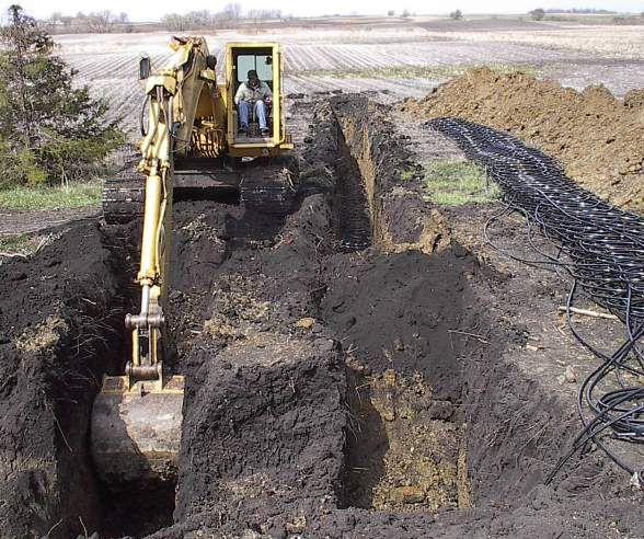
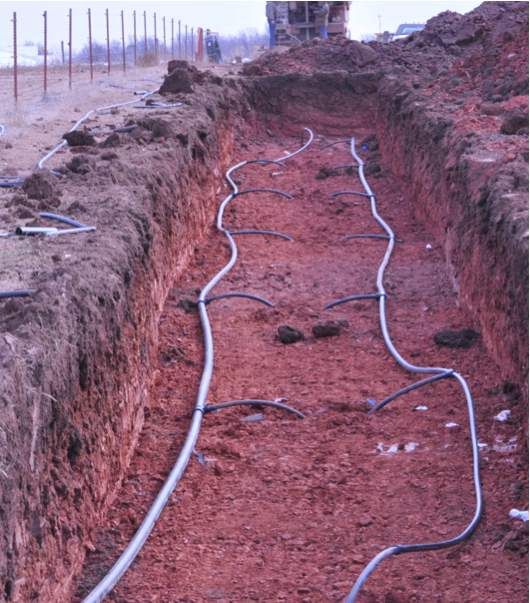
Several trends suggest that a growing market will emerge for air-to-water heat pumps.

5. Air-to-water heat pumps are significantly less disruptive to install
compared to geothermal heat pumps:

Horizontal earth loops require large land areas and
major excavation.
In my area, vertical earth loops cost about $3,000+ per
ton for drilling, pipe insertion, and grouting. Additional
cost is incurred for connecting multiple vertical piping
loops, and routing piping back to the location of the
heat pump. The drill “tailings” usually have to be
removed from the site.

Replacement of any                                           www.thegeoecchange.org
affected pavements or
landscaping also
needs to be factored
into the cost of
installing a geothermal
heat pump system.
Several trends suggest that a growing market will emerge for air-to-water heat pumps.

6. As home space heating loads get
smaller, the domestic water heating load
becomes an increasingly higher
percentage of the total annual heating
energy requirement.

                                                                                 Water
                                                                                heating
Some estimates put the DHW load at 25-30 percent of                            COP = 1.0
the total annual energy requirement in a well insulated
modern home.

Most ductless mini-split heat pumps cannot provide
domestic water heating, but a properly configured air-to-
water heat pump can.

A standard electric water heater providing domestic water heating in a
situation where the heat pump can not, delivers heat at a COP of 1.0.
If that energy was instead attained through an air-to-water heat pump,
it could be delivered at a COP averaging perhaps 2.5 over the year.
For a family of 4, needing 60 gallons per day of water heated from 50
to 120 ºF, and assuming electrical energy priced at $0.12 per KWHR,
                                                                         Water heating
the difference in annual domestic water heating cost between these
scenarios is $270.
                                                                         COP = 2.5+
Several trends suggest that a growing market will emerge for air-to-water heat pumps.
7. The high COP cited for some Example of a commercially
geothermal heat pumps doesn’t available earth loop flow center.
include the power required to move 4, UP26-150 circulators (370 watts
flow through the earth loop. each) = 1,480 watts pumping
power input.
The ANSI 13256-2 standard for geo heat pump COP includes an estimate for the power required to move flow
through the heat pump - BUT DOESN’T INCLUDE ANY ALLOWANCE FOR THE EARTH LOOP PUMPING
POWER.
The high flow and head required in some geothermal earth loops requires substantial circulator power.
Example: A specific water-to-water geothermal heat pump has the follow listed performance information:
Earth loop entering temperature = 30ºF
Entering load water temperature = 100 ºF
Flow rate (both evaporator and condenser) = 9 gpm
Heating capacity = 27,700 Btu/hr
Electrical power input = 2370 watts
Based on a typical earth loop, the pumping requirement is 10.5 gpm at 35.5 feet of head. This equates
to an estimated pump input of 287 watts.
Btu Btu
27700 27700
COPHP only = hr = 3.42 COPHP +loop pump = hr = 3.05
⎛ Btu ⎞ ⎛ Btu ⎞
3413 3413
( 2.37kw ) ⎜⎜ hr ⎟ ⎜
( 2.37kw + 0.287kw ) ⎜ hr ⎟
kw ⎟ kw ⎟
⎜⎝ ⎟⎠ ⎜⎝ ⎟⎠
Nominal 11% drop in “net” COPOther (unique)
air-to-water heat
pumpsSplit system air-to-water heat pump
Nordic air-to-water heat pump
INDOOR UNIT
compressor
refrigerant-to-water heat exchanger
reversing valve
controls
desuperheater (for DHW)
OUTDOOR UNIT
(major components)
air-to-refrigerant heat exchanger
fanBring your own condenser... ThermAtlantic Energy Products, Inc.
Bring your own condenser...                                                                             Heating mode
                                                                                 Heat pump routes heat to buffer tank
                                            absorbed!                            Heat delivered from buffer
                                        (low temperature)!
                                               heat                              tank to low temperature load

                                                                                                 chilled water air handler

                                        ON
    air source heat pump!                                                                                       OFF
         outdoor unit
     temperature sensor

                                                                                                                                               zone!
                                                                                OFF                                                        thermostats

                                                                                                                             manifold
                                                                                      controls                                 valve
                                                                                                                             actuators

                                                                                                           ON
                                                                                                                       electric!
                                                                                                                        boiler
                                                                                                                                         zoned radiant !

                                                               ON            DX2W module                          ON!                    ceiling panels

                          buffer tank                        open                                           (supplemental)!
                                                                    closed

                                                             open
Bring your own condenser... Cooling mode
Heat pump chills buffer tank
rejected!
heat
Chilled water delivered to air handler for latent
cooling, & mixing chilled water to radiant panels
for sensible cooling
chilled water air handler
ON
air source heat pump! ON
outdoor unit
zone!
ON thermostats
manifold
controls valve
actuators
ON
electric!
boiler
zoned radiant !
ON DX2W module OFF ceiling panels
(cooling mode operation)
buffer tank partially!
open
partially!
open
mixed39
Heating performance:
(inverter drive scroll compressor unit)

                               leaving water temperature     95 ºF                                               95 ºF
                                                           131 ºF                 leaving water temperature
                                                                                                              131 ºF
                           80000                                                   5
                                                                                  4.5
                                                                                   4
                           60000
    heat output (Btu/hr)

                                                                                  3.5
                                                                                   3

                                                                            COP
                           40000                                                  2.5
                                                                                   2
                                                                                  1.5
                           20000
                                                                                   1
                                                                                  0.5
                              0
                                                                                   0
                                   -5   5    15 25 35 45 55 65         75
                                                                                        -5    5    15 25 35 45 55 65         75
                                            outdoor temperature (ºF)
                                                                                                  outdoor temperature (ºF)

                                   Heating capacity                                          COP
                                   Increases with:                                           Increases with:
                                   a. warmer outdoor temperature                             a. warmer outdoor temperature
                                   b. lower load water temperature                           b. lower load water temperature
Heating performance:
OUTSIDE
INSIDE
HEATING MODE
outside air load water
temperature!
"lift"!
(less is better)
load water
outside air
Anything that reduces the “temperature lift” increases
both the heating capacity and COP of the heat pump.
Low temperature distribution systems are critical to good
performance.Cooling performance:
Daikin Alterma model ERLQ054BAVJU Daikin Alterma model ERLQ054BAVJU
leaving chilled water temp = 59 ºF leaving chilled water temp = 59 ºF
leaving chilled water temp = 55 ºF leaving chilled water temp = 55 ºF
leaving chilled water temp = 50 ºF leaving chilled water temp = 50 ºF
leaving chilled water temp = 45 ºF leaving chilled water temp = 45 ºF
Energy Efficiency Ratio (EER) (Btu/hr/watt)
70000 14
13
65000
Cooling capacity (Btu/hr)
12
60000
11
55000 10
9
50000
8
45000
7
40000 6
60 65 70 75 80 85 90 95 100 105 60 65 70 75 80 85 90 95 100 105
Oudoor air temperature (ºF) Outdoor air temperatue (ºF)
Cooling capacity EER
Increases with: Increases with:
a. lower outdoor temperature a. lower outdoor temperature
b. Higher chilled water temperature b. higher chilled water temperatureCooling performance:
OUTSIDE
INSIDE
COOLING MODE outside air
outside air
temperature! chilled water
"lift"!
(less is better)
chilled water
Anything that decreases the temperature lift’ increases
both the cooling capacity and EER of the heat pump.
Warmer chilled water temperatures improve performance.LOW-AMBIENT Air-to-Water Heat Pump Systems
evaporator
                                                      outside!                                 outside!
                                                        air                           fan        air

                        Standard
                                                                                            !

                      refrigeration                                                     compressor

                          cycle                                                                           condensor

                                                                                                                 water out

             evaporator                                                                                         water in
                                                                        (main) TXV!
                                                                          thermal
outside!                                  outside!                       expansion
  air                           fan         air                            valve

                                                      vapor injection port
                                  EVI enabled!
   EVI allows                     compressor               electronic expansion
    increased
   refrigerant
                                                           valve
                                                            condensor
                                                                                                 EVI
 mass flow into
 evaporator, &
     at lower
                                                                      water out             refrigeration
     entering
 temperatures.                                                         water in                 cycle
                  (main) TXV!               refrigerant!
                    thermal                "sub-cooler"               solenoid
                   expansion                                          valve
                                                 sub cooled!
                     valve
                                                 liquid refrigerant
Freeze protection
Simplest option: Use antifreeze solution in entire system
OUTSIDE
INSIDE
entire system filled with
antifreeze solution
pressure relief valve
air separator
remainder
of system
air-to-water heat pump
flexible connectors
expansion tank
fill / purge valvesHeat exchangers between heat pump maximum!
approach!
and distribution system temperature!
difference!
OUTSIDE
(heating)
INSIDEMy own installation... February 2015 Upstate NY -23 ºF air temperature -29 ºF wind chill Feb 7, 2018
Design objectives:
1. Be able to serve as heat source
for building with 18,000 Btu/hr
design load (via radiant floor
heating).

2. Retain oil-fired boiler and allow
simple manual selection of heat
source. (flip of switch)

3. Provide zoned chilled water
cooling for 1st floor office, and 2nd
floor guest room.

4. Be equipped for BTU metering
of energy from heat pump &
KWHR meter of electrical energy to
heat pump (to calculated COP, and
EER)
Supporting the heat pump

Treated lumber pedestal to keep unit
above snow level

                                       Added 2 threaded rods w/ base
                                       flanges to stiffen pedestal
Piping details to keep condensate out of wall framing
1” FPT copper adapter
2” PVC sleeve
wrap with electrical tape
for tight fit
1” Chamflex hoses with offset to
allow small movement
foam sealant
insidehigh wall fan coil
1/2” FPT to
propex adapter
1/2” MPT lines
on air handler
end of
condensate
drain hose
HW-18-ECM (@ 2.1 gpm flowrate)
25000
20000
Heat ouput (Btu/hr)
15000
10000
5000
0
condensate drain direct 70 80 90 100 110 120 130 140 150 160
through outside wall Entering water temperature (ºF)Importance of low
temperature
distribution systemsHeat sources such as condensing boilers, geothermal & ATW heat pumps,
and solar collectors all benefit from low water temperature operation.
5.1
Coefficient Of Performance (COP)
4.9
4.7
4.5
4.3
4.1
3.9
3.7
3.5
100 105 110 115 120 125
Entering water temperature (ºF)
0.8
0.7
thermal efficiency (decimal %)
0.6
0.5
0.4
0.3
0.2
ambient air temp. = 30ºF!
0.1
solar radiation = 250 Btu/hr/ft2)
0
60 80 100 120 140 160 180 200
inlet fluid temperature (ºF)“FUTURE PROOF” your hydronic systems... Select heat emitters, and design hydronic distribution systems so that they can supply design load output using supply water temperatures no higher than 120 ºF. Even lower design load supply temperatures are preferred when possible. This is especially important when renewable energy heat sources are used.
Water temperature ranges for various hydronic heat emitters
 • The heat output of any heat emitter always drops with decreasing water temperature.
 • There is always some output provided the supply water temperature is above the
 room air temperature.
 • There is always a trade off between the total surface area of the heat emitters in the
 system, and the supply water temperature required to meet the heating load.

 • More heat emitter area always lowers the required supply water temperature.

      120 ºF, suggested maximum supply water temperature for modern systems

                                                                                          traditional cast-iron radiators
                                                                                          traditional fin-tube baseboard

                                                                                                                                  NOT RECOMMENDED
                                                                              fan-coils
                                                      panel radiators
                        ceiling heating
                          wall heating
                                                underfloor tube&plate
                                   above floor tube&plate
                                          thin slab
                            covered heated slab
      floor heating (bare slab)

 80        90        100          110       120         130       140   150     160         170        180       190        200

 • Don’t feel constrained to select heat emitters based on traditional supply water
 temperatures…
Slab-on-grade floor heating
tube
spacing
4"
concrete
slab
6-inch tube spacing
12-inch tube spacing
Rff=0 Rff=0.5
60
upward heat flux!
Rff=1.0
(Btu/hr/ft2)
40 Rff=1.5
Rff=2.0
20
0
0 10 20 30 40 50 60 70 80 90 100
Driving ∆T (Tw-Tr) (ºF)!
Average water temp. - room air temp
Rff = resistance of finish flooring (ºF/hr/ft^2/Btu)Don’t do this with ANY hydronic heat source! Heat transfer between the water and the upper floor surface is severely restricted!
Don’t do this with ANY hydronic heat source!

Heat transfer between the water and the upper floor surface is severely restricted!
Hydronic heat emitters options for low energy use houses

Most CONVENTIONAL fin-tube baseboard has been sized around boiler
temperatures of 160 to 200 ºF. Much too high for good thermal
performance of low temperature hydronic heat sources.

Could add fin-tube length based on
lower water temperatures. BUT...

Fin-tube output at 120 ºF is only
about 30% of its output at 200ºF
Hydronic heat emitters options for low energy use houses
Some low- temperature baseboard is now available
Hydronic heat emitters options for low energy use houses
Panel Radiators
One of the fastest responding hydronic heat emitters

 From setback to almost steady state in 4 minutes…
Hydronic heat emitters options for low energy use houses
Panel Radiators
• Adjust heat output for operation
at lower water temperatures.

                                As an approximation, a panel radiator operating with
                               an average water temperature of 110 ºF in a room
                               room maintained at 68 ºF, provides approximately 27
                               percent of the heat output it yields at an average water
                               temperature of 180 ºF.
Fan-assisted Panel Radiators
The “NEO”, just released from Runtal North America
8 tube high x 31.5” wide produces 2095 Btu/hr at
average water temperature of 104 ºF in 68ºF room
8 tube high x 59” wide produces 5732 Btu/hr at average
water temperature of 104 ºF in 68ºF roomSite built radiant CEILINGS…
Thermal image of radiant ceiling in operation
Heat output formula:
q = 0.71× (Twater − Troom )
Where:
Q = heat output of ceiling (Btu/hr/ft2)
Twater = average water temperature in panel (ºF)
Troom = room air temperature (ºF)Site built radiant WALLS…
Site built radiant WALLS…

                                                  Heat output formula:
• completely out of sight
• low mass -fast response
                                                     q = 0.8 × (Twater − Troom )
                                                  Where:
• reasonable output at low water temperatures
• stronger than conventional drywall over studs   Q = heat output of wall (Btu/hr/ft2)
                                                  Twater = average water temperature in panel (ºF)
• don’t block with furniture                      Troom = room air temperature (ºF)
System Examples
Reverse indirect tank buffers space heating &
significantly preheats domestic water
                                                                                             (ZP1)               (T1)
         Source: Turbomax tanks

                                             entire system filled with                       (ZP2)               (T2)
                                               antifreeze solution

                                                   OUTSIDE

                                                             INSIDE
                                                                                                                        point-of-use
                                                                                                                        instantaneous
                                                                                                                        water heater

                                  SPACEPAK
                                                                             (MV1)
                                                                                     (SPC)                              ASSE
                                                                                                                        1070
                                                                                             (S1)                       valve
                                                                                                                                DHW
                                                 (S2)
                                                                                                                                 CW

                                                                      (P1)
                                                                                              reverse indirect
                                                                                               water heater /
                                                                                                buffer tank
        Solstice Extreme   (HP)                       flexible
    air-to-water heat pump                          connectors
Reverse indirect tank buffers space heating &
significantly preheats domestic water
DESCRIPTION OF OPERATION:
(ZP1) (T1)
Power supply: The Solstice heat pump, circulator (P1), and motorized valve
(MV1) are powered by a dedicated 240/120 VAC 30 amp circuit. The heat pump
disconnect switch (HPDS) must be closed to provide power. The remainder of
entire system filled with (ZP2) (T2)
antifreeze solution the control system is powered by 120 VAC 15 amp circuit. The main switch (MS)
must be closed to provide power. The instantaneous water heater is supplied by
OUTSIDE
a dedicated 240 VAC / 60 amp circuit.
INSIDE
point-of-use Heat pump operation: Whenever the main switch (MS) is closed 120 VAC is
instantaneous
water heater
passed to the multi-zone relay center (MZRC). The (MZRC) passes 24 VAC to
(MV1)
SPACEPAK
the temperature setpoint controller (SPC) which monitor the temperature at
(SPC) ASSE
1070
(S1) valve
DHW
sensor (S1) in the buffer tank. If the temperature at sensor (S1) is below 105 ºF,
(S2)
CW the (SPC) closes its contact, which completes a circuit between terminals 15 and
16 in the Solstice Extreme heat pump, enabling it to operate in heating mode.
After a short time delay, circulator (P1) and motorized valve (MV1) will be
(P1) supplied with 120 VAC from the heat pump. This establishes flow of the system’s
reverse indirect
water heater /
buffer tank antifreeze solution through the heat pump. The heat pump verifies adequate
Solstice Extreme (HP) flexible
air-to-water heat pump connectors flow using its internal flow switch, and when adequate flow is proven, starts the
heat pump in heating mode. The 120 VAC supplied to (MV1) opens the valve
240/120 VAC allowing flow between the heat pump and the headers of the thermal storage
30 amp circuit
L1 L2 N L1 N G
tank. The system continues in this mode until the temperature at sensor (S1)
heat pump 120 VAC / 15amp circuit
disconnect reaches 125ºF, at which point the contacts in the setpoint controller (SPC) open
switch main (T1) (T2)
(HPDS)
switch turning off the heat pump, circulator (P1) and motorized valve (MV1).
instantaneous (MS)
water heater
240 VAC Space heating: Whenever the main switch (MS) is closed, 24 VAC is sent to
60 amp (P1)
circuit L thermostats (T1, T2). When either thermostat calls for heating its associated
N
Solstice (MZRC) zone circulator (ZP1, ZP2) is turned on.
Extreme
heat pump
(MV1) 15 16 17 18 Domestic water heating: Domestic water passes through the copper tubing
coils suspended in the buffer tank. The tank temperature at sensor (S1) is
(HP)
(SPC) maintained between 105 and 125 ºF. Domestic water passing through the coil
R C
(ZP1) (ZP2)
(S1) will be preheated (or at time fully heated) as it passes through this coil. Any
sensor
additional temperature rise of the domestic water is provided by the tankless
electric water heater.Cold climate air-to-water heat pump system radiant panel mainfold station 1
• 2 zones of radiant panel heating
(AH1) OFF
• 2 zones of chilled water cooling
• 80 gallon buffer tank
• High efficiency variable speed distribution circulator (ZVH1)
(ZVC1)
• Direct-to-load supply side piping OFF
radiant panel mainfold station 2
(ZVH2)
(AH2) OFF
HEATING MODE (ZVC2)
All piping and components OFF
conveying chilled water must
be insulated and vapor sealed
OUTSIDE
INSIDE
entire system filled with (P2)
propylene glycol
antifreeze solution
spring
check (ORC)
SPACEPAK
valve (S2)
outdoor
(S1) temperature
(S3) sensor
temperature
sensors
(SPC)
(P1)
heated buffer tank
Solstice Extreme (HP) flexible
air-to-water heat pump connectorsCold climate air-to-water heat pump
• 2 zones of radiant panel heating (AH1)
• 2 zones of chilled water cooling
• 80 gallon buffer tank OFF
(ZVH1)
• High efficiency variable speed distribution (ZVC1)
circulator
• Direct-to-load supply side piping
(ZVH2)
OFF (AH2)
COOLING MODE (ZVC2)
All piping and components
conveying chilled water must
be insulated and vapor sealed
OUTSIDE
INSIDE
entire system filled with (P2)
propylene glycol
antifreeze solution
spring
check (ORC)
valve
SPACEPAK (S2)
(S1)
(S3)
temperature
sensors
(SPC)
(P1)
heated buffer tank
Solstice Extreme (HP) flexible
air-to-water heat pump connectorsCold climate air-to-water heat Description of operation:
pump system Power supply: The Solstice Extreme heat pump and circulator (P1) are powered by a
dedicated 240/120 VAC 30 amp circuit. The heat pump disconnect switch (HPDS) must be
closed to provide power to the heat pump. The remainder of the control system is powered
by 120 VAC / 15 amp circuit. The main switch (MS) must be closed to provide power to the
240 VAC 240/120 VAC
15 amp circuit 30 amp circuit
control system. Both fan coils are powered by a dedicated 120 VAC / 15 amp circuit. The
L1 L2 G
heat pump
L1 L2 N G L1 N G service switch for each air handler must be closed for that air handler to operate.
disconnect 120 VAC / 15amp circuit
switch main
(HPDS) switch
Heating mode: The mode selection switch (MSS) must be set for heating. This passes 24
(MS)
VAC to the RH terminal in each thermostat. Whenever either thermostat demands heat,
(P1) L1 L2 24VAC is passed from the thermostat’s W terminal to the associated zone valve (ZVH1, or
L
N ZVH2). When the zone valve reaches its fully open position its internal end switch closes,
Solstice
Extreme
passing 24 VAC to relay coil (R1). Relay contact (R1-1) closes to pass 120 VAC to
heat pump
circulator (P2). Relay contact (R1-2) closes to pass 24VAC to outdoor reset controller
15 16 17 18
(ODR). The (ODR) measures outdoor temperature at sensor (S2), and uses this
temperature along with it settings to calculate the target supply water temperature for the
buffer tank. It then measures the temperature of the buffer tank at sensor (S1). If the
(R2-3)
(R1-1)
temperature at (S1) is more than 3 ºF below the target temperature the (ODR) closes its
(R2-1) relay contact. This completes a circuit between terminals 15 and 16 in the Solstice extreme
heat pump, enabling it in heating mode. After a short time delay the heat pump (HP) turns
(P2) on circulator (P1) and verifies adequate flow through the heat pump. After a short time
transformer delay the heat pump compressor turns on it compressor. The heat pump continues to
120/24 VAC
(MSS) 24 VAC operate until the temperature at sensor (S1) is 3 ºF above the target temperature calculated
Mode
by the (ODR), or neither thermostat calls for heat, or the heat pump reaches it internal high
heat
cool
service selection
(AH1) switch off switch (RC)
L1
limit setting. Note: Neither air handler operates in heating mode, regardless of the fan
L2 (R1) switch setting on the thermostats.
G R G
(RC-1) (R2)
RC Cooling mode: The mode selection switch (MSS) must be set for cooling. This passes
RH
(ZVH1)
24VAC to relay coil (RC). normally open contacts (RC-1) and (RC-2) close allowing 24VAC
service W M
(AH2) switch from the air handlers to pass to the RC terminal in each thermostat. Whenever either
G
L1
L2
thermostat calls for cooling, 24VAC is passed from the thermostat’s Y terminal to the
Y M
G R G thermostat
associated zone valve (ZVC1, or ZVC2). When the zone valve reaches its fully open
(T1) (ZVC1)
(RC-2) position its internal end switch closes, passing 24 VAC to relay coil (R2). Relay contact
RC
RH
(ZVH2) (R2-1) closes to pass 120 VAC to circulator (P2). Relay contact (R2-2) closes to pass
W M
24VAC to the cooling setpoint controller (SPC). The cooling setpoint controller measures
G
the temperature of the buffer tank at sensor (S3). If this temperature is 60 ºF or higher, the
Y
thermostat
M
(SPC) relay contact closes completing a circuit between terminals 15 and 16 on the Solstice
(T2) (ZVC2) Extreme heat pump (HP) enabling it to operate. Relay contact (R2-3) closes between
terminals 17 and 18 in the Solstice Extreme heat pump (HP), switching it to cooling mode.
(R1-2) (ORC)
R C The heat pump (HP) turns on circulator (P1) and verifies adequate flow through the heat
(S1)
pump. After a short time delay the heat pump compressor turns on it compressor and
(S2)
sensors operates in chiller mode. This continues until the temperature at sensor (S3) drops to 45 ºF,
or until neither zone thermostat calls for cooling, or until the heat pump reaches in internal
(R2-2) (SPC)
R C
low limit setting. The blowers in the air handlers can be manually turned on at the
(S3) thermostats when the mode selection switch (MSS) is set to cooling. The blowers will
sensor
operate automatically whenever either cooling zone is active.Dynamic Duo: hydronic heat pump + boiler This combination provides the following benefits: • The mod/con boiler can serve as a “peaking tool” to meet peak loads when necessary. • The heat pump can be smaller in capacity relative to design load. This is helpful in applications where the cooling load is significantly smaller than the design heating load. • Having a mod/con boiler as a secondary heat source provides full or partial backup if the heat pump is not operating. • The boiler’s electrical power demand is relatively small compared to the heat pump. This makes it more feasible to operate the heating system from a modestly-sized backup generator during power outages. • In areas where time-of-use electrical rates are available, it would be possible to operate the heat pump when off-peak rates are in effect, and avoid high on-peak rates by using the boiler as the heat source.
towel warmer
Heating + Cooling +DHW
radiator air vent
thermostatic operator
air vent
Self-contained (2-stage)
TRV
air-to-water heat pump w/ dual isolation valve
mod/con auxiliary boiler
Single thermal mass tank mod/con boiler
PEX, or 2-stage temperature
PEX-AL-PEX tubing setpoint controller (SPH)
variable speed
circulator (P2)
Supplies: isolation and
•
flushing valves
zoned space heating for potable side
of HX
•
manifold station
P&T
single zone cooling temp. DHW
(P3)
(HX)
•
sensor
domestic hot water (S1)
(FS1)
• automatic aux boiler buffer
OUTSIDE
INSIDE
tank
(P4)
diverter
N.C.
valve A
(DV1)
AB
2 stage or inverter drive B
N.O.
heat pump very important (P1) spring-loaded
check valves
to avoid short cycling in Solstice SE
cooling mode. air to water heat pump
(AH1)
Entire system filled with propylene (S2)
single zone
air handler
for
glycol antifreeze solution. coolingHeating + Cooling +DHW Electrical Wiring
240 VAC
L1 L2 N L1 N
towel warmer 120 VAC
radiator air vent
thermostatic operator main
switch
(MS)
air vent
L (HP)
TRV
dual isolation valve (P1) N
Solstice
SE
heat pump
(RH2-1)
43
44
(P2)
5
6
mod/con boiler (Rdhw-1) (P4)
(RH1-2)
PEX, or 2-stage temperature (RB-1) (AH1)
PEX-AL-PEX tubing setpoint controller (SPH)
variable speed
circulator (P2)
mod/con
isolation and
boiler T
(RH1-1)
flushing valves
for potable side (B1) T
of HX
manifold station
P&T
(P3)
temp. DHW
(P3)
(HX)
sensor transformer
(S1) 120/24 VAC
(FS1)
24 VAC
(Rdhw)
buffer
OUTSIDE
INSIDE
tank (FS1)
(P4)
diverter
valve
N.C.
A (SPH)
R C
(DV1)
AB
(S1) stage 1
(RH1)
B
N.O. sensor
2-stage
Mode
setpoint
selection stage 2 controller (DV1)
switch
cool
cool
spring-loaded
heat
(P1)
check valves
(MSS)
off off
Solstice SE
air to water heat pump RC
RH (RH2)
W
(AH1)
G (RB)
(T1) Y
single zone master
(SPC)
air handler thermostat R C
(S2) for
cooling
(S2)
sensorHeating + Cooling +DHW Description of Operation Please read this later in the PDF Heat Source Operation: When the main switch (MS) is closed, power is available to the line voltage and low voltage portions of the electrical system. 24VAC is applied to power up the 2-stage setpoint controller (SPH). This controller (SPH) measures the temperature at sensor (S1) in the upper portion of the thermal storage tank. If that temperature is below the user-set stage1 setpoint (in this case 125 ºF), minus half the user-set differential (in this case half the differential is 5 ºF), then the stage 1 contacts in (SPH) close. For space heating operation, the (DPDT) mode selection switch must be set to heat. This passes 24VAC to the RH terminal of the master thermostat (T1). It also allows 24 VAC to pass from the stage 1 contacts in the (SPH) controller to energize the diverter valve (DV1) and relay coil (RH1). Relay contact (RH1-1) closes between terminal 43 and 44 on the Solstice SE heat pump turning it on in the heating mode. Relay contact (RH1-2) opens between terminals 5 and 6 on the Solstice SE heat pump allowing it to operate in heating mode. An internal relay within the heat pump turns on circulator (P1). Heat from the heat pump flows to the upper header of the buffer tank. The heat pump and these associated devices continue to operate as described until sensor (S1)in the buffer tank climbs to a temperature of 130 ºF, or if the master thermostat (T1) stops calling for heat. If, during a call for space heating from master thermostat (T1), the temperature at sensor (S1) in the upper portion of the buffer tank drops to 115 ºF, the stage 2 contacts in the setpoint controller (SPH) will close. These contacts complete a low voltage circuit powered through the boiler, and enable the boiler to operate in a fixed upper temperature mode. The boiler turns on circulator (P3) through an internal relay. The boiler continues to operate until the buffer tank sensor (S1) reaches a temperature of (130 ºF), at which point the boiler turns off, and so does circulator (P3). Note: The boiler will operate in this mode regardless of whether the mode selection switch is set to heat or cool. This allows the boiler to maintain a suitable temperature in the buffer tank for domestic water heating even when the heat pump is operating as a chiller. Space Heating Distribution: When master thermostat (T1) calls for heat, 24VAC passes from its W terminal to energize the coil of relay (RH2). Contact (RH2-1) closes to pass 120 VAC to circulator (P2). This circulator is set to operate in constant differential pressure mode to provide the necessary flow to any panel radiator that does not have its thermostatic valve fully closed. Circulator (P2) will automatically vary its speed to maintain approximately constant differential pressure across the manifold station serving the panel radiators. The thermostatic valves on each radiator can be used to limit heat input as desired. Domestic Water Heating Mode: Whenever there is a demand for domestic hot water of 0.6 gpm or more, flow switch (FS1) closes. This passes 24VAC to energize the coil of relay (Rdhw). Contact (Rdhw-1) closes to pass 120 VAC to circulator (P4). Heated antifreeze solution flows from the upper portion of the buffer tank will flow through the primary side of heat exchanger (HX), and transfer heat to the cold domestic water flow through the secondary side of the heat exchanger (HX). When the demand for domestic hot water drops to 0.4 gpm or less, flow switch (FS1) opens. This turns off relay (Rdhw) and circulator (P4). All domestic hot water leaving the system passes through a thermostatic mixing valve to limit the water temperature to the distribution system. Cooling Mode: For cooling operation the mode selection switch (MSS) must be set to cool. This passes 24 VAC to the RC terminal of the master thermostat. If the master thermostat is set for cooling operation, and calls for cooling, 24VAC is passed to its Y terminal. From the Y terminal, 24VAC passes to energize the coil of relay (RB). A normally open set of contacts (RB-1) close to pass 120 VAC to the air handler (AH1) turning it on. 24VAC also passes from the Y terminal of the master thermostat to energize cooling setpoint controller (SPC). Once energized, (SPC) monitors the temperature of sensor (S2) on the inlet pipe to the air handler. If that temperature is above 60 ºF the contacts in (SPC) close. This completes a circuit between terminals 43 and 44 in the Solstice SE heat pump, turning it on in cooling mode. The heat pump turns on circulator (P1) through its internal relay. All necessary devices for cooling operation are now active. The system remains in cooling operation until either the cooling demand is removed at thermostat (T1), or the temperature at sensor (S2) on the air handler inlet drops to 40 ºF, at which point the heat pump, circulator (P1), and air handler (AH1) turn off.
Thanks for attending today’s session                 recently released!
                                                864 pages, full color textbook

          Questions?
Please visit our website for more information
www.hydronicpros.com
Coming in 2018
You can also read