DRE Engineering Updates - Frankie Greco, Joel Hornburg & Ray Charoen 2020 - aps
←
→
Page content transcription
If your browser does not render page correctly, please read the page content below
DRE Engineering Updates
Frankie Greco, Joel Hornburg & Ray Charoen

 2020
Agenda Topics
• Departments/Teams:
 Roles and
 Responsibilities
• ACC DG Interconnection
 Rules & APS Alignment
• Inspection process & PTO
• Q&A
• Appendix (Engineering
 Workshop Discussion)

What do we do?
Roles & Responsibilities
• Perform DG Hosting Capacity (HC) evaluations, DER
 Forecasting/modeling and support Interconnection Study
 Processes
• Evaluate Interconnection Applications for Safety/Reliability
 (i.e. System Impact)
• Provide clarification/input on the APS Interconnection
 Requirements and APS Interconnection Agreements
• General technical input pertaining to Interconnection
 practices (customer inquiries)
• Consulting/pre-design services for both APS Owned
 Programs (micro-grids and E.V. chargers) and 3rd party
 customers (key accounts, developers, etc.)
• Technical support for APS field personnel (i.e. meter-sets,
 compliance checks and supply side taps/connection issues)
ACC & APS IRM Updates/Alignment
Timeline of Events:
• June 2019: Rev 8.3 of the APS Interconnection Requirements
 Manual go into effect
 – Advanced Inverter Requirements
 – ATS processes
 – SSC & Commissioning/testing requirements
• October 2019: Rev 8.4 of the APS Interconnection
 Requirements Manual go into effect
 – Emergency update addressing 3rd party inspections
• November 2019: ACC Approves Article 26, Interconnection of
 Distributed Generation Facilities
• Formal Rule Adoption Process now Underway:
 – March 2020 (estimated): Article 26 expected to be published/posted into
 the AG Register
 – May 2020 (estimated): Utility and Customer compliance of Article 26,
 Interconnection of Distributed Generation Facilities is required
 – May 2020 (estimated): Utility and Customer compliance of Article 26,
 Interconnection of Distributed Generation Facilities is required
 – August 2020 (estimated): APS to file Rev 8.5 of the APS Interconnection
 Requirements
ACC & APS IRM Updates/Alignment
(cont.)
What’s changing with the APS IRM?
• Insurance required only for rotating machine projects (i.e. Backup
 Generation Projects)
• Some NEW definitions as noted in ACC DG IR:
 – Various Studies (FaS, FeS, SiS)
 – Minor Modifications
 – Screens
• 3rd Party Inspection Report Required for SSC installations in areas
 where no AHJ inspection takes place
• APS Interconnection Application (Appendix A – C) removed and
 creation of the “APS Interconnection Application Process Guide” to be
 posted to APS.COM/DG
• Interconnection Application Screens (Section 17), clarifies each screen
 into more “Customer Friendly” language
• Customers and Customer Representatives Shall comply with both ACC
 DG Interconnection Rules and APS Interconnection Requirements
 Manual
ACC/APS Interconnection
 Requirements
Objectives of Updated Process
• Improve Customer Experience
• Protect safety and reliability of
 the grid
 – Application screens
 • Ensure safety of GFs to be
 installed
 • Prevent GFs from negatively
 impacting power quality to other
 customers, and safety/reliability
 of grid.
• Follow consistent review process
 and timelines as determined by
 system sizing
 – Establishes time frames for
 processing an application
 throughout the steps in each track
ACC/APS Interconnection
 Requirements
Apply to all systems that interconnect to the grid
• System Categories
 – Exporting Systems
 • PV, Battery, anything that regularly exports to the grid
 – Inadvertent Export Systems
 • Programmed Not to Export, (PV + Inverters/Battery)
 – Non-Exporting Systems
 • Separate Systems, Back Up Only
• 4 Review Tracks based on system size/category
 – Expedited (Inadvertent Export System under 20 kW)
 – Super Fast (Exporting Systems under 20 kW)
 – Fast (Systems between 20 kW and 2 MW)
 – Study Track (Systems over 2 MW)
Screens for Systems under 20 kW
• Screen A
 – Limits the aggregate generation that can be interconnected to a
 distribution line without additional study.
 • Under 15% of annual peak load, or
 • Under hosting capacity calculated for that distribution line
 (whichever is greater)
• Screen E
 – Limits the aggregate generation capacity on a single-phase
 shared secondary to under 75% of the transformer rating
 without additional study
• Screen F
 – Limits the current imbalance of a system connected to a single
 phase system that is connected to a transformer providing
 120/240V secondary service to under 20% of the rating of the
 transformer between the two sites of the 240 V service.
General Application Review Process for
Systems under 20 kW

 Customer
 Application

 Application Customer
 Technical Review and
 + Completeness
 Review
 (Within 7 Days)
 Complete
 Screening (A, E, F)
 (Within 14 Days)
 Pass
 Installation

 Installer
 Application

 Deficient Fail

 Customer
 Customer/Installer Customer
 Selects
 Make Corrections System Pass
 Supplemental
 (Within 30 Days) Modifications
 Review
General Installation Process for
Systems under 20 kW

 Customer
 Installation

 Compliance Send follow up
 APS Review of
 Check/ PTO
 + Installation
 Documents
 Complete
 APS Meter Set Leave PTO door
 hanger
 communication
 within 2-5 days

 Customer
 Submit Post
 Installation
 Documentation

 Deficient

 Customer/Installer
 Make Corrections
 (Within 30 Days)
Supplemental Review
• Generally for systems that fail 1 or more of the technical screens
• General Supplemental Review Process:

 APS Requires
 Supplemental
 Review

 Customer Submit
 APS Provide cost
 Payments and APS complete
 estimate and Customer
 Required Study (Within 21 Approve
 OR written agreement
 documentation for Days)
 Installation
 for study (Within 7
 Applicable Studies
 Days)
 Customer (Within 14 Days)
 Requests
 Supplemental
 Review Deficient

 Customer/Installer
 Make Corrections, or
 move to Study Track
 (Within 30 Days)
Study Track
 • Generally for systems over 2 MW
 • Can be used for systems that do not pass technical screening
 requirements in Levels 1 and 2
 • Studies may include (Feasibility, System Impact, Facility). APS
 will work with Customer on Process.
 • General Study Track Process:
Pre-Application
 Meeting for
Systems over 2
 MW, Submit
 Application Customer
 Provide
 Submit
 Applicable Study Complete
 Application Payments and
 Set Study Scoping Agreements Applicable
 Completeness Complete Required
 OR Review (Within 30
 Meeting (Within 21 and study cost
 estimates(Withi
 documentation
 Studies (Within
 45 days)
 Days)
 Customer days) for Applicable
 n 14 Days)
Submit Required Studies
 docs as
indicated by APS Deficient
 in Level 1/Level Approve
 2 review
 Deficient

 Customer/Installer Customer
 Make Corrections Installation
 (Within 30 Days)

 Customer/Installer
 Make Corrections
 (Within 30 Days)
Courtesy Reviews

• APS DRE Engineering no longer supports courtesy
 reviews.
• ACC Rules allow customer to request a Pre-
 Application report
 – Pre-App reports include available info on feeder
 conditions
 – May require a fee
• Refer to online resources aps.com/dg
Summary of Resources Available at
www.aps.com/dg

• Rev 8.5 APS IRM (TBD)
• PV & ESS Templates
• Updated Sample diagrams
• Inspection guidelines
• Installer Checklist
• Plan-review checklist
• 2020 Training guide (TBD)
• DG ESRM Section 1400 (TBD)
IEEE 1547 & Advanced Inverter Standards &
 Settings
All inverters interconnecting to the APS system should have advanced
inverter capability as of publication of Rev 8.3 of the APS Interconnection
Requirements.

APS to Determine Settings
• Initial settings will not negatively impact customer performance
• APS advanced inverter policy document
• APS advanced inverter setting sheet

How Does this Fit within the APS Interconnection Requirements
manual?
• Section 8.7(A)(11) Outlines the various capabilities documented within
 IEEE 1547
• Most/all inverter manufacturers should have Advanced Inverter
 capabilities

APS Understandings/Expectations
• Advanced inverter settings validation
Inspections and Compliance Checks
Shifting focus and enhancing efficiencies from Site
Ready to PTO, APS Inspection processes are
changing slightly:

• APS Field Services (Residential) completes all meter-sets and
 compliance checks (no change)
• APS Meter Shop (Commercial) will follow similar model for our
 Residential customers (time-frame TBD)

No AHJ Inspection, what now?
• APS field personnel are not NEC/workmanship experts, therefore we
 recommend all installers provide a 3rd party inspection (guidelines will
 be available at aps.com/dg)
• APS field personnel reserve the right to request a 3rd party inspection
 report if workmanship is questionable
 – Will be required for all Supply Side Connections (APS will not validate nor will we
 request the physical report unless workmanship appears to be sub-par)
 – APS will only validate/ensure our equipment (UDS and Metering) are properly
 labeled, matches approved diagrams and maintains required 24-7 access.
Questions?
Required Diagrams for PV Systems
(Residential and Small Commercial Larger than 1kW, < 1MW)
 • Residential
 – Electrical One-Line Diagram*
 – Electrical Three-Line Diagram
 – Site Plan
 • Commercial
 – Electrical One-Line Diagram
 – Electrical Three-Line Diagram & Three-Line Array
 – Plant Location
 – Site Plan
 APS will not accept copyrighted, proprietary or confidential drawings. Drawings
 shall be site specific without any extraneous information, and shall be prepared
 specifically for APS use. All drawings are to be professionally drawn, using only
 black print on white paper, and shall be in accordance with APS Sample Diagrams.
 Battery Backup Systems may have other drawing requirements in addition to
 standard drawings as required by APS.

 NOTE: Customer should discuss project plans with APS
 before designing its DG or purchasing and installing
 equipment.

 * Electrical one line diagrams are only required for three
 phase DG systems.
Sample 1-Line Diagram
Example - Residential PV System
Sample Site Plan
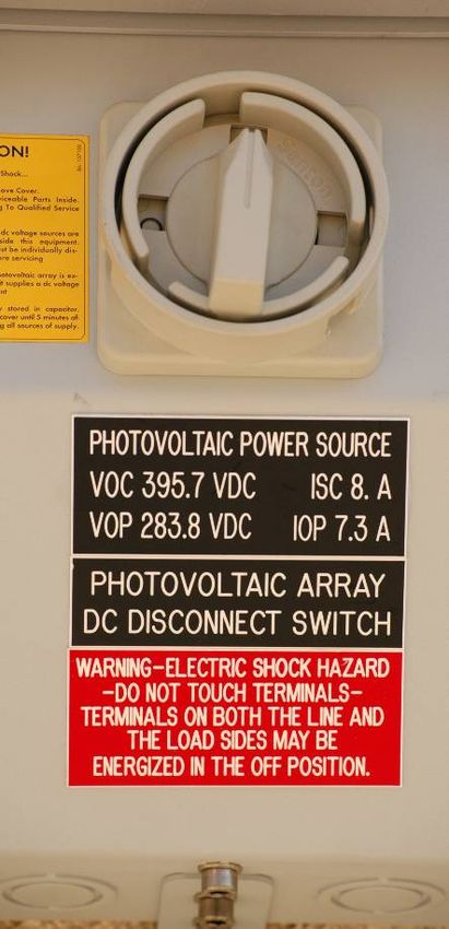
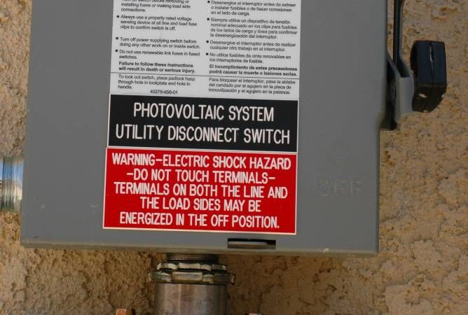
Example of PV System Warning Labels

NOTE: Typical APS Equipment Labels Handout is located at
www.aps.com/dg. ANSI color standards may be used, but
isn’t required by NEC or APS.
Example of PV System Warning Labels (cont.)
NEC 705.10 – Requirements for Directory
From NEC 705.10:
“A permanent plaque or directory, denoting all
electric power sources on or in the premises, shall
be installed at each service equipment location
and at locations of all electric power production
sources capable of being interconnected.
Exception: Installations with large numbers of
power production sources shall be permitted to be
designated by groups.”

This requirement has not been uniformly
enforced.
Standard Interconnection Requirements:
Disconnect Switch (Utility Disconnect): Section 8.2
• Must be locked with an APS Padlock with a 3/8” shank.
• Must be placed in a safe, unobstructed location, available 24 hours
 a day.
• Shall be installed in accordance with the NEC and APS
 requirements, and the center of the pivot handle of the switch shall
 be located between 36” and 60” above grade and include a 36”
 square clear working space.
• If the Disconnect switch is not located within close proximity to the
 SES, APS requires a placard at the SES with explicit directions as to
 the location of the disconnect switch:
Standard Interconnection Requirements:
Disconnect Switch (cont.)
– The “Utility Disconnect Switch” blades, jaws and air
 gap between them shall be clearly visible when the
 switch is in the open position.
– Blades shall always be on the Inverter Side, and shall
 be de-energized in the open position in accordance
 with NEC 404.6(C) and OSHA 1926.405(C).
– Arc shields are acceptable only if they do not impede
 our ability to verify a visual open. NOTE: Arc
 shields may not be removed in order to verify
 the visual open.
– Multiple Utility Disconnects are allowed in the event
 of a system expansion just as long as the disconnect
 switches are properly labeled and contain switch
 numbers (i.e. 1 of 2, 2 of 2).
– Note that APS requires a fused disconnect
 ahead of the APS required unfused disconnect
 to meet fault current requirements (Refer to
 APS ESRM 800.2):
 • The required fused disconnect shall be locked by
 the customer/installer, and does not need to
 meet APS visual open requirements like the APS
 required Utility Disconnect Switch.
Standard APS Interconnection
 Requirements:
Production Metering
Customer must provide and install, at
Customer’s expense, meter sockets
and metering cabinets in accordance
with APS service standards, in
locations acceptable to APS
• Shall be ring-type. Ring-less is not
 permitted.
• 36” X 36” working space
• Meter height must be between 48”
 and 75” from finished grade to the
 center of the meter socket.
• CT rated production metering
 sections shall have suitable visual
 open disconnecting means, subject
 to APS approval.
Standard APS Interconnection Requirements:

Production Metering

All CT rated metering
enclosures shall have
the bus identified with
reference to the
generation source
side prior to metering
installation with a
temporary tag labeled
“Generation Source”.
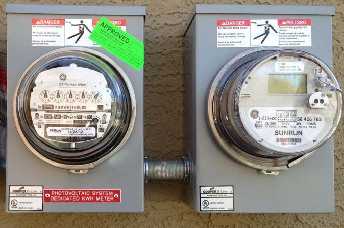
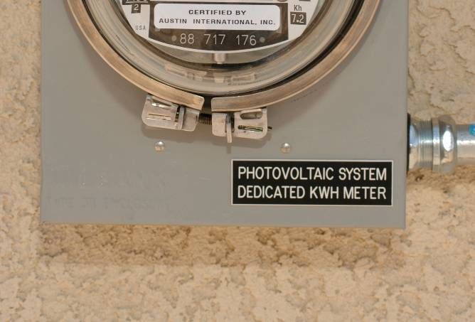
Standard APS Interconnection Requirements:
Production Metering (cont.)
 – 3rd Party Production Metering
 • Customer’s installing 3rd party
 production meters, may do so
 just as long as the 3rd party
 meter is correctly labeled and is
 located on the inverter side of
 the APS Production Meter.
 – Multiple Production Metering
 • An example would be a system
 expansion in which the Customer
 has an existing Incentive and
 wishes to expand the system by
 adding a non-program system.
 Production Meters shall be APS Production
 properly labeled with meter Meter labeled
 identification (i.e. 1 of 2, 2 of 2). “Photovoltaic
 System Meter” or 3rd Party Production
 “Photovoltaic Meter labeled
 System “Leasing Company
 Dedicated kWH PV Production Meter”
 Meter.”
Standard APS Interconnection
 Requirements:
Production Metering (cont.)
 – Meter Cover vs. Test Meter
 • Residential customers may verify PV/Solar
 production with use of a test meter. Note that flats
 or jumpers are not permitted.
 • Additionally, for residential customers, In lieu of
 providing a Production Meter, Customer may install a
 commercially available meter cover over the
 Production Meter Socket.

 NOTE:
 Cardboard is not
 an acceptable
 cover material.
 Cover material
 shall be fiberglass,
 plastic, glass or
 Plexiglas.
Standard APS Interconnection Requirements:
Production Metering (cont.)
ESRM 301.15: ELECTRIC METER
SEPARATION BETWEEN WATER AND
GAS
 – The Production Meter is subject to this
 requirement.
 – Based on the NFPA Gas Code & the
 Arizona Gas Pipeline Standards
 • Require a 36” radial clearance
 from a “venting source” of a gas
 system to any “potential source of
 ignition.”
 • APS interprets the “potential
 source of ignition” the edge of the
 meter panel, and the “venting
 source” the gas regulator.
 • Working Clearance shall be a • Water valves or hose bibs within the
 minimum of 36” wide. If electric 36”X36” Safe Work Area are
 panels extend wider than the 36” prohibited.
 minimum, working clearance shall
 be the width of the entire • Drain pipes or soffits are prohibited
 assembly. Working space extend above the meter enclosure to ensure
 out from the face of electric meter the 36”X36” Safe Work Area remains
 panel a minimum of 36”. safe and dry.
Standard APS Interconnection Requirements:
 The Utility Disconnect Switch and Production Metering Enclosure
 shall be installed in a Readily Accessible location:
 Readily Accessible as defined by APS: Capable of being reached
 quickly and conveniently on a 24-Hour basis without requiring climbing
 over or removing obstacles, obtaining special permission, keys or security
 clearances.
 ‒ Commercial Applications: If access is restricted for security
 reasons, subject to APS approval, a lock-box may be provided to gain
 access to the Utility Disconnect Switch and/or Production Metering as
 long as the lock box is installed within 36” of the door/gate and located
 between 36” and 60” from finished grade.
 ‒ The Utility Disconnect Switch and/or Production Metering Shall not be:
 1. Located behind an electrically operated gate or door unless the
 electric operator is backed up by a UPS to ensure it can be
 operated in the event of a utility power outage.
 2. Installed under a breezeway, patio, porch or any area that can be
 enclosed.
 3. installed behind a gate, fence, wall or other barrier unless
 expressly agreed to by APS (we may grant exceptions for
 Commercial customers).
Supply Side Connection
— Allowed per 2011/2014/2017 NEC 705.12 (A):
 • “The output of a utility-interactive inverter shall be permitted to be
 connected to the supply side of the service disconnecting means as
 permitted in 230.82 (6)” (similar to installing a second service per APS
 ESRM 104.11.2).
— RMC (Rigid Metal Conduit) between the connection and the fused
 disconnect.
— Ampere rating of conductors between fused disconnect and connection
 shall not be less than the ampere rating of the disconnect.
— Neutral to ground bond must be re-established in the fused disconnect,
 and tied to GEC.
 • Note that if the SSC is made via a breaker or fused disconnect located
 within the SES, then the existing N-G bond will suffice (i.e. Solar
 Ready Panels).
— Fused Disconnect must be adjacent (within 10’) to SES, subject to ESRM
 301.12 requirements, NEC 225.32, 230.79(D) & 240.24(B).
— MFG approval in writing or UL field evaluation and certification for SSC is
 required (i.e. letter of compliance and approval sticker).
Supply Side Connection (cont.)
‒ No connections allowed inside the APS Sealed CT/Metering
 Compartments.
‒ Fused and unfused conductors shall not occupy the same
 raceway unless they are isolated from each other via a firewall
 barrier in a manner acceptable to APS.
‒ Disconnecting/opening the main breaker will not
 disconnect the PV system.
‒ Warning label shall be located at the main service with the
 following language:

‒ APS will only operate the Photovoltaic System Utility
 Disconnect Switch, as this is our clearance point.
‒ For most applications, APS will require two disconnect switches
 (exception to this would be an approved “Solar Ready” panel)
Supply Side Connection (cont.)
Supply Side Connection (cont.)

 NEC 250.94
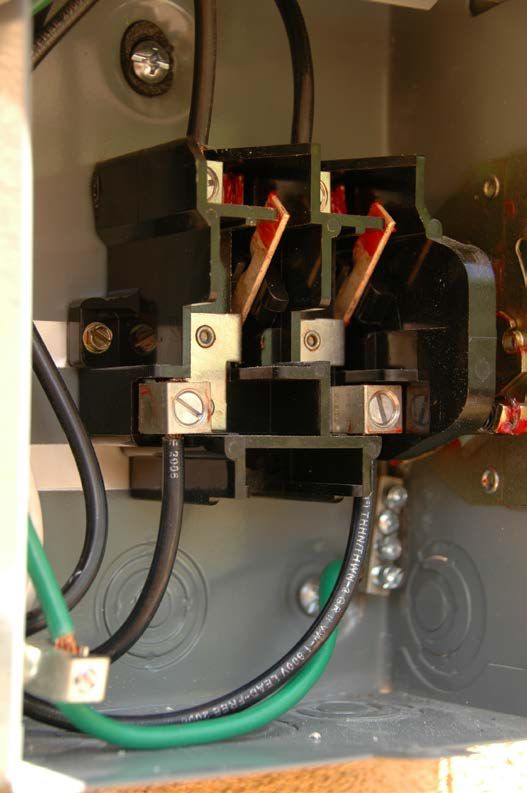
Supply Side Connection – Don’t Do This

Don’t
remove
factory
installed
conducto
rs

 UL
 Listing of
 panel
 was
 violated -
 entire
 service
 entrance
 panel
 had to be
 replaced
 in order
 to pass
 city and
 APS
 inspectio
 ns
PE Stamp Requirements
APS clarified when PE Stamp and AHJ Permit is required
• For Residential Systems, Electrical drawings stamped by a Professional
 Engineer (Electrical) registered in the State of Arizona OR may provide a copy
 of the building permit issued by the AHJ when specifically required by Utility in
 writing
• For Commercial Systems, Electrical drawings stamped by a Professional
 Engineer (Electrical) registered in the State of Arizona

 NOTE: APS may require a copy of the building permit issued by the AHJ
 when specifically required by Utility in writing

What to do if an AHJ doesn’t issue a permit for PV/Energy
Storage System:
• Once APS approval is granted, in accordance with SB1417, install GF following
 APS and NEC applicable requirements
• Sign and provide the “Letter In-Lieu of Electrical Clearance” form to APS

 NOTE: Additional information available per Section 16 of the
 APS Interconnection Requirements manual
Battery Back-Up Systems Background

• Sometimes installed in conjunction with Photovoltaic Systems
• In the event there is an APS outage (planned or unplanned), the
 customer’s critical loads are powered by the battery back-up system
• Opening the Utility Disconnect Switch may not kill all AC
 power feeding the Home
• Customer’s may opt to activate “Grid-Sell” or “Battery Charger”
 modes. Either option is acceptable to APS
• The installation of a bypass switch (manual or automatic transfer
 switch) is acceptable just as long as proper warning signs and written
 procedures/instructions are provided
• Some battery backup applications require specific metering (“Grid
 Sell” mode) if the customer wishes to net out any load
• Installer is required to provide operating instructions for proper
 isolation of AC power to the home as well as isolation instructions for
 the inverters for home owner, First Responders and maintenance
 personnel that may work on the system from time to time
• Inverters listed to UL1741/UL1741SA.
Battery One Line Example

 Only One
 Utility
 Disconnect • Isolation needed on
 Switch per both sides of ESS
 DG System Production meter
 • ADS Opens upon Grid
 Outage
 Metering • Protected Load Panel
 Isolation for not normally 24-7
 maintenance accessible
 • Backup with Peak
 Shaving vs. Peak
 Shaving only: May
 have different isolation
 requirements
Automatic
Disconnect
Switch
(internal)
Peak Shaving

• PV Panels and Critical load panel is not
 required.
• Normally will have either one or two
 inverters
• In the event of an outage, the system
 will shut down
• Multiple configurations available for
 metering and isolation
• Battery system (via a DC to AC inverter)
 is programed to provide a portion of the
 load draw to the customer’s electric
 service via CTs and communication
 circuitry
AC Coupled Systems
• Normally installed in conjunction with a separate PV
 System.
• Battery System will draw power from the utility to
 keep batteries charged
• Essential loads placed in-between PV System and
 main electric service
• In the event of an outage: (1) PV system ceases to
 operate, (2) Isolation Relay opens up, and (3)
 Battery System will power the essential load panel
• The Battery System metering will be required
• APS will require a Utility Disconnect Switch at each
 system (PV and Battery Back-up), and a Production
 Meter at the PV system
DC Coupled Systems
• Installations normally by Outback Power Systems
• This is a one (or two) inverter system with both batteries
 and panels connected to the inverter (separate inputs)
• Essential load panel is installed as an output to the
 inverter
• Inverter DC Disconnect and Bypass switch required to
 disconnect power to the Essential Load panel
• In the event of an outage: (1) back-feed controller to
 the grid is disabled, (2) essential loads are powered by
 the batteries with the PV panels (or optional generator
 input) charging batteries
• APS will require Utility Disconnect Switches & Production
 Meters
• Meters required would be 2S, but older design could be
 12S electro-mechanical
• NOTE: Batteries must be fully charged prior to APS
 Meter-Set
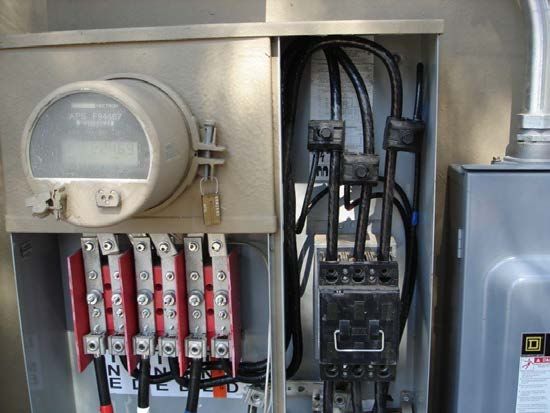
Battery Back-Up Systems (cont.)
 GF Meters and Utility Disconnect Switch
 (Common for 240V Systems)
This is an example of two 2S
production meters installed for a
120/240V battery backup system
(Outback DC Coupled Type)
 • For testing purposes, Customers
 may provide electro-mechanical
 meters. Meter-sockets shall be
 labeled per APS requirements
 • Each Meter is comprised of a
 utility energy component and an
 output circuit component
 • APS will change out meters to AMI • Customer’s shall apply NEC
 type metering for remote reads 300.3(B): All conductors of the
 (could occur prior to PTO) same circuit (including the neutral
 • ACC mandates that APS accounts and ground) shall be contained
 for all customer owned power within the same raceway, conduit,
 production sources that nets out gutter, cable tray, etc.
 load that otherwise would be
 served by APS
Standby Battery Systems
• Installed for backup power only, will not backfeed the
 APS System
• Only systems utilizing a transfer switch tested, listed and
 marked UL 1008 will be considered as a separate system
• Off-grid and/or other systems not utilizing a UL 1008
 listed transfer switch will be required to sign a
 connection agreement with APS, demonstrate to APS
 that the system does not backfeed the utility, and will be
 required to install a visual open disconnect switch in
 accordance with Section 4.1 and 8.2 of the APS
 Interconnection Requirements Manual
• APS is in development of short process document to aid
 with the installation of standby systems (battery and
 generators)
Breaker & Wire Sizing
Breaker Sizing: NEC (2011) 690.8(A)(3), 690.8(B)(1)(a),
240.6(A)

 Inverter AC Output Current Rating X 1.25

1Ø : Inverter AC Output Current Rating = Inverter Watts÷Voltage
 Inverter Watts
3Ø: Inverter AC Output Current Rating =
 Voltage X √3

Example: 2-8kW Static Inverters in Parallel (120/240V, 1Ø, 3W).
Calculate the AC output Current, Determine the correct breaker size
and wire.

 8kW/240V = 33.3A X 1.25 = 41.6A
 OCPD = 45A (combiner box)

 In Parallel
 16kW/240V = 66.6A X 1.25 = 83.3A
 OCPD = 90A (back-fed breaker)
Breaker & Wire Sizing (cont.) Wire Sizing NEC (2011) 690.8(B)(2) Table 310.15(B)(16) - 90⁰C Column X Temp Correction [Table 310.15(B)(2)(A)] Table 310.15(B)(16): Assume an ambient temp of 105-113⁰F Temp Correction = 0.87 41.6A (circuit to combiner previous slide) 55A X 0.87 = 47.85A Use 1-#8 Cu THWN-2 per phase In Parallel 83.3A (parallel circuit previous slide), 95A X 0.87 = 82.7A < 83.3A 115A X 0.87 = 100A Use 1-#3 Cu THWN-2 per phase NOTE: If wire length is less than 10’ OR less than 10% of the run is above ground, then a temperature correction factor may not be required.
Voltage Drop/Rise Calculation
 Voltage Drop/Rise Equation
 Ω
 ‒ = 2 × × ×
 1 �
 ‒ L = length of circuit (one-way)
 ‒ A = load amps (inverter output)
 Ω
 ‒ = based on conductor from
 1 �
 NEC Table 9

• Example:
 – 85 feet conductor run
 – 7.68kW inverter Ω
 Single phase – 240V • = 2 × 0.78 × 85 × 32
 • 1 �
 7.68kW/240V=32A
 •
 • Unity power factor
 • = 4.2
 4.2
 – #8 CU conductor • % = = 1.8%
 Ω
 240V
 • 0.781 � from Table 9
Voltage Rise Calculation (Cont.)

 This voltage drop calculator
 can be found online. Search
 for ‘Siemens voltage drop
 calculator’ on the web.
Fault Current Calculations

– Table 800.2-1 of the APS ESRM provides the worst case
 fault current values from the utility utilizing the infinite bus
 method.
 (https://www.aps.com/library/esp%20services/800.pdf)
 • Fault tables assume 80% loading and 25’ of conductor length including Ins
 and Outs (sweeps)
 • Based on lowest impedance values (APS publishes ranges for your use if
 needed on the APS ESRM website (www.aps.com/esrm)
– A customer is determining fault current value at their DG
 System Disconnect Switch, the following information is
 needed:
 • DG System Size (for breaker and conductor validation)
 • Distance from the main service to the disconnect switch
 • Conductor type (wire properties are available via the
 NEC and also Short Circuit Calculation Section out of the
 Bussman-Eaton manual)
– Add inverter contribution (1.5 times is industry standard,
 but some modeling programs assume 2 times).

 A useful fault current calculation
 program that APS uses is available
 via www.mikeholt.com
Fault Current Calculations (Cont.)
– Example 1: 200A Service @ 120/240 V, 1Φ, 50 foot of #8 Cu,
 breaker size is 40A, 7500W single phase 120/240 V inverter.
 • what is the fault current at the disconnect?
Fault Current Calculations (Cont.)
– Example 2: 800A Service @ 277/480 V, 3Φ, 100 foot of #4 Cu,
 breaker size is 90A, 8-7500W three phase inverters (60 kW).
 • what is the fault current at the disconnect?
Common Errors and Violations
1. Drawings were not per APS Samples: i.e. block drawings vs. schematic
 drawings, text not legible at 11X17, etc..
2. Grounding and bonding issues: case ground for individual equipment not
 shown, bond jumpers as required by NEC 250.64(E)(1) & 690.47(C)(3), and
 supply side connection grounding.
3. Wire sizing issues: ensure compliance with NEC 240.4(B), identify insulation
 and if Cu or Al.
4. Fault Current Calculations: APS requires compliance with recently updated
 ESRM 800.2, NEC Art 110.9 & NEC Art 110.10.
 a. If a fused disconnect is not shown on the line side of the APS required
 Utility Disconnect Switch, APS will require fault current calculations to
 verify compliance.
 b. Note that most unfused disconnect switches are rated for only 10k AIC.
5. NEC and APS Required Labels Missing: Refer to APS Equipment Labels
 (Interconnection Requirements & Equipment Labels available via
 www.aps.com/dg) & various NEC code references. Label references shall be
 identified on diagrams.
6. Required Keyed Notes: APS Engineering will reject applications missing this
 information Keyed Notes.
7. Access/Workspace Notes: Provide 24-hr access, workspace clearance and
 meter separation between water and gas notes.
Common Errors and Violations (cont.)
8. Production Meter orientation: APS requires the Utility Disconnect
 switch to be located on the line/utility side of the APS production meter.
 If a leasing company production meter is installed, it shall be located
 on the load/inverter side of the APS required production metering.
9. Installation prior to approval: SB 1417 mandates that a distributed
 energy generation system cannot be installed, energized, or
 interconnected until the utility has approved the application.
10.Other common issues:
 a. Wrong size tap kit for supply side connection
 b. Blades for disconnect switches facing the wrong direction
 c. Lack of details and ambiguity on drawings
 d. Missing one line diagram on applications
 e. Terminals on meters not properly shown, line and load side for bi-
 directional meters missing, missing information on form type, ring
 type
 f. Combiner panels being labelled as load center
 g. Colored drawings not allowed
Rapid Shutdown of PV Systems
For the 2011 version of the NEC NFPA 70, 690.11 “DC Arc-Fault Circuit
Protection” was added to mitigate fire initiation hazards associated
with arcing faults, but does nothing to eliminate shock hazards
associated with PV power circuits.
• For the 2014 version of the NEC NFPA 70, 690.12 “Rapid Shutdown of PV
 Systems on Buildings” was added.
• A listed device that controls specific PV System conductors (5’ in length
 inside a building or 10’ distance from a PV array).
• No specifics as to the location of the rapid shutdown initiating device to allow
 AHJs, System Integrators and First Responders the flexibility to locate
 devices and warning labels at location most appropriate for the specific
 installation.
• Limit of 30 volts and 240 volt-
 amperes with 10 seconds of
 initiation.
• Solar optimizers (DC-DC
 Contactors) can be used for
 rapid shut down (i.e. Tigo
 Energy retro-fit solution or
 SolarEdge whole system
 solution).
• Microinverters or ac modules inherently comply with 690.12 as loss of AC power
 immediately de-energizes all PV system circuits outside the array areas.
• Warning label in accordance with 2014 NEC 690.56(C).
NEC Code References
– Six Handle Rule: NEC 230.71(A)
 • In the event we have six disconnects and no main, customer wants to add a 7th
 breaker for a back-fed device (PV). Some AHJs consider this a violation others
 consider PV as a separate source and exempt from NEC 230.71(A).
 • Systems without a main need to consider NEC 230.90(A), Exception No. 3:
 The sum of the ratings of CBs/fuses shall be permitted to exceed the ampacity of the
 service conductors provided the calculated load doesn’t exceed the ampacity of the
 service conductors. Provide load calculations to APS, panel schedules and
 consider PV into the load calculations provided.
– Main Breaker De-Rate: NEC 230.79
 • If customer is in violation of the 120% Rule [NEC 2011_ 705.12(D)(2)], customer
 may de-rate the main in order to accommodate the installation of a PV system. Load
 calculations will be required by the AHJ and APS prior to de-rating the main breaker.
 APS can provide 12 month historical load to the customer for calculation purposes
 [NEC 220.87].
 • Note 12 Month historical Loads are provided in kW. To convert from kW to kVA, we
 assume a 0.91PF for residential and 0.85PF for commercial
 • A placard/label is required per APS Requirements.
– GEC: NEC 250.66, NEC 250.166
 • For new services, customers shall review APS ESRM 701.0.
 • PV Systems requiring a GEC installed back to the SES, may consider NEC 250.166,
 690.47(C)(2).
– Non-isolated (Transformerless) Inverters
 • Not addressed very well in the 2011 NEC, typical practice is to install ONLY an EGC in
 accordance with NEC 250.122.
 • Some inverters are shipped with a GEC terminal, some are not. Decision as to install
 a GEC is left up to the AHJ for these types of Inverters.
 • 2014/2017 NEC covers this topic in better detail [NEC 690.47(C)(3)]: For
 ungrounded systems, this conductor shall be sized in accordance with 250.122 and
 shall not be required to be larger than the largest ungrounded phase conductor.
Step Up Xfmr Fault Current Calculations
Example 3: 800A Service @ 120/208 V, 3Φ, 50 foot to utility disconnect
switch and production meter, then 50’ to step up xfmr 75 kVA (~128 A of
backfeed)

Useful Formulas: 3Φ = 3Φ
 ; = ; Isc RMS = ISC x M;
 +
C = conductor constant ; n = number of conductors per
phase; I = available short circuit current (in amps); E =
voltage;
L = length of conductor

 Step 1: Starting Isc from APS for above configuration is 49,505A

 Step 2: install ~ 50’ of 3-1/0 Cu in metallic conduit (C = 8925; n = 1)
 f = 2.3607; M = 0.30242, Isc = 14,971 A + ISCDER

 Step 3: install ~ 50’ of 3-1/0 Cu in non-metallic conduit (C = 9317; n =
 1)
 f = 0.6876 M = 0.5925, Isc = 9130.61 A + ISCDER

 Step 4: Step voltage from 120/208V, 3Φ to 277/480V 3Φ; %Z (75 kVA)
 is 4.5%
 × × ×% . × × . ×( . )
 = , ×
 = , ×
 = 1.974; M = +
 = + .
 = 0.3363

 × × × . × .
 Isc =
 =
 = 1330.6 A + ISCDER

 NOTE: Don’t forget to add the potential DG contribution to all steps (~
 128 A X 2 = 256 A @ 208 V, and 55.5 A X 2 = 111 A @ 480 V)
Open Delta Transformers

‒ Installed in older areas of APS service
 territory (i.e. North-Central Phoenix,
 Downtown Phoenix, Rural areas,
 Tempe, Chandler, Paradise Valley and
 Central Scottsdale)
‒ Secondary voltage of 120/240V, limited
 to 25 horsepower motor load and
 50kVA 3-phase load
‒ Comprised of two transformer
 configuration made up of a power pot
 and a liter pot.
 • Power pot is where two pole loads can • Customer load is generally not balanced
 be connected (no center tap neutral on for these configurations.
 the power pot, so connecting single • Liter Pot sees 100% of the 1-phase load +
 phase load is not permitted). 58% of the 3-phase load.
 • Liter pot can have a combination of • Power Pot sees 58% of the 3-phase load
 single pole and two pole loads. • APS recommends installing inverters
 • Three phase loads are connected across across A-B and A-C. Keep in mind not
 all three phases. to over-duty the APS transformers
 tied across A-B and A-C.
IEEE 1547-2018 Category B Reactive Power
 Capability and Voltage Regulation
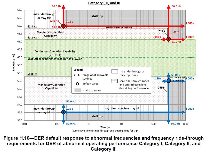
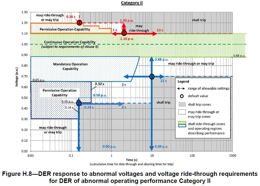
IEEE 1547-2018 Category 2 Response to
 Abnormal Conditions (Voltage)
IEEE 1547-2018 Category 2 Response to
 Abnormal Conditions (Voltage)
IEEE 1547-2018 Category 2 Response to
 Abnormal Conditions (Frequency)
IEEE 1547-2018 Category 2 Response to
 Abnormal Conditions (Frequency)
References and Sources for Further Information
 APS Commercial Renewables
 Phone: (602) 371-6160, email: commercial-renewables@aps.com
 web: http://www.aps.com/dg

 NEC: National Electrical Code, Section 690 “Solar Photovoltaic Systems”
 NEC: National Electrical Code, Section 705 “Interconnected Electric Power
 Production Sources”
 “Understanding NEC Requirements for Solar Photovoltaic Systems” – Mike
 Holt
 IEEE Std 1547-2018: IEEE Standard for Interconnecting Distributed
 Resources with Electric Power Systems Interfaces
 IAEA: A Closer Look at Batteries, John Wiles – 09/16/2013
 Eaton/Bussman Short Circuit Analysis – 2014 Application Guide

 APS Requirements:
 1. APS “Interconnection Requirements for Distributed Generation”
 http://www.aps.com/dg
 http://www.aps.com/main/green/choice/choice_79.html
 2. APS “Electric Service Requirements Manual” (ESRM)
 http://www.aps.com/main/services/construction/corner/corner_66.html
You can also read