Detecting Architectural Erosion using Runtime Verification - mediaTUM
←
→
Page content transcription
If your browser does not render page correctly, please read the page content below
Detecting Architectural Erosion
                             using Runtime Verification

                      Diego Marmsoler         https://orcid.org/0000-0003-2859-7673

                                     Technische Universität München, Germany
                                           diego.marmsoler@tum.de

                       Ana Petrovska         https://orcid.org/0000-0001-6280-2461

                                     Technische Universität München, Germany
                                            ana.petrovska@tum.de

      The architecture of a system captures important design decisions for the system. Over time, changes
      in a system’s implementation may lead to violations of specific design decisions. This problem is
      common in the industry and known as architectural erosion. Since it may have severe consequences
      on the quality of a system, research has focused on the development of tools and techniques to ad-
      dress the presented problem. As of today, most of the approaches to detect architectural erosion
      employ static analysis techniques. While these techniques are well-suited for the analysis of static
      architectures, they reach their limit when it comes to dynamic architectures. Thus, in this paper, we
      propose an alternative approach based on runtime verification. To this end, we propose a systematic
      way to translate a formal specification of architectural constraints to monitors, which can be used to
      detect violations of these constraints. The approach is implemented in Eclipse/EMF, demonstrated
      through a running example, and evaluated using two case studies.

1    Introduction
A system’s architecture captures major design decisions made about the system to address its require-
ments. However, changes in the implementation may sometimes change the original architecture, and
some of the design decisions might become invalid over time. This situation, sometimes called architec-
tural erosion [13], may have severe consequences on the quality of a system and is a common, widespread
problem in industry [11, 14]. Thus, research has proposed approaches and tools to detect architectural
erosion which, as of today, focus mainly on the analysis of static architectures and therefore employ
static analysis techniques [9, 10, 15, 17, 31, 32].
     However, recent trends in computing, such as mobile and ubiquitous computing, require architectures
to adapt dynamically: new components may join or leave the network and connections between them
may change over time. Thereby, architectural changes can happen at runtime and depend on the state of
the components. Thus, analysis of erosion for dynamic architectures requires the analysis of component
behavior, and therefore it is only difficult, not to say impossible, to detect with static analysis techniques.
     Consider, for example, the following scenario: An architect, to satisfy important memory require-
ments, decides to implement the Singleton pattern to restrict the number of active components of a
specific type. Since the developers are not familiar with this memory requirement, they modify the code
in a way that they create multiple instances of the corresponding type. Detecting the corresponding
architectural violation with static analysis tools is difficult, not to say impossible.

To appear in EPTCS.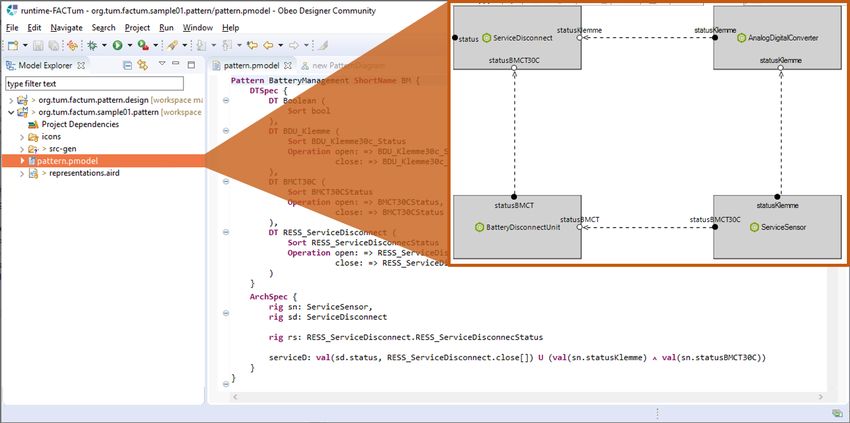
2                                                              Detecting Architectural Erosion using RV

    Thus, traditional approaches to detect architectural erosion may reach their limits when it comes to
dynamic architectures. To address this problem, we propose a novel approach to detect architectural
erosion, based on runtime verification [18]:
    • First, architectural assertions are formally specified in FACT UM [22], a language for the formal
       specification of dynamic architectural constraints.
    • Second, code instrumentation and monitors are generated from the specification.
    • Finally, the monitors are used to detect architectural violations at runtime.
To this end, we developed two algorithms to map a given FACT UM specification to corresponding events
and LTL-formulæ over these events.
    We evaluated the approach on two case studies from different domains. In the first case study, we ap-
plied the approach in a controlled environment for the analysis of an open-source Java application in the
domain of Business Information Systems. Accordingly, we implemented the algorithms for Java applica-
tions, specified architectural constraints in FACT UM, and generated monitors and code instrumentation.
Finally, we executed the system and observed it for violations.
    The second case study was executed in a real, industrial setting, in which we applied the approach for
the analysis of a proprietary C application in the automotive domain. To this end, we first implemented
the algorithms for C applications. Again, we specified architectural constraints in FACT UM and gener-
ated corresponding monitors and code instrumentation. Lastly, we executed the system observing it for
architectural violations.
    With this paper, we provide two major contributions:
    • We describe a systematic way to detect architectural erosion for dynamic architectures using run-
       time verification techniques and demonstrate its applicability using a running example. To this end,
       we also describe two algorithms for mapping a FACT UM specification to corresponding events and
       LTL-formulæ over these events.
    • We show the feasibility of using runtime verification to detect architectural erosion through two
       case studies.
The paper is structured as follows: We first provide some background on FACT UM (Sect. 2) and runtime
verification (Sect. 3). Then, we introduce our approach and demonstrate each step using a simple, running
example (Sect. 4). In (Sect. 5) we present the two case studies. Finally, we discuss related work (Sect. 6)
and conclude the paper with a summary and limitations that lead to potential future work (Sect. 7).

2     Specifying Dynamic Architectures in FACT UM
FACT UM [22] is an approach for the formal specification of constraints for dynamic architectures. It
consists of a formal system model for dynamic architectures and techniques to specify constraints over
this model. FACT UM is also implemented in terms of an Eclipse/EMF application called FACT UM
Studio [24], which supports a user in the development of specifications.

2.1   System Model
In our model [21, 25], components communicate with each other by exchanging messages over ports.
Thus, we assume the existence of set M , containing all messages, and set P, containing all ports,
respectively. Moreover, we postulate the existence of a type function

                                            T : P → ℘(M )                                              (1)
D. Marmsoler and A. Petrovska 3
which assigns a set of messages to each port.
Port valuations. Ports are means to exchange messages between a component and its environment.
This is achieved through the notion of port valuation. Roughly speaking, a valuation for a set of ports is
an assignment of messages to each port.
Definition 2.1 (Port valuation). For a set of ports P ⊆ P, we denote with P the set of all possible,
type-compatible port valuation, formally:
n o
def
µ ∈ P → ℘(M ) | ∀p ∈ P : µ(p) ⊆ T (p) .
P =
Moreover, we denote by [p1 , p2 , . . . 7→ M1 , M2 , . . .] the valuation of ports p1 , p2 , . . . with sets M1 , M2 ,
. . ., respectively. For singleton sets we shall sometimes omit the set parentheses and simply write
[p1 , p2 , . . . 7→ m1 , m2 , . . .] .
In our model, ports may be valuated by sets of messages, meaning that a component can send/receive
a set of messages via each of its ports at each point in time. A component may also send no message at
all, in which case the corresponding port is valuated by the empty set.
Interfaces. The ports which a component may use to send and receive messages are grouped into
so-called interfaces.
Definition 2.2 (Interface). An interface is a pair (I, O), consisting of disjoint sets of input ports I ⊆ P
and output ports O ⊆ P. The set of all interfaces is denoted by IF P . For an interface if = (I, O), we
denote by
def
• in(if ) = I the set of input ports,
def
• out(if ) = O the set of output ports, and
def
• port(if ) = I ∪ O the set of all interface ports.
Components. For the purpose of this paper, we assume the existence of a set of components (Cif )if ∈IFP .
A component port is a port combined with the corresponding component identifier. Thus, for a family of
components (Cct )if ∈IFP over a set of interfaces IF P , we denote by:
def
• in(C ) = ({c} × in(c)), the set of component input ports,
S
c∈C
def
• out(C ) = ({c} × out(c)), the set of component output ports,
S
c∈C
def
• port(C ) = in(C ) ∪ out(C ), the set of all component ports.
Moreover, we may lift the typing function (introduced for ports in Eq. 1), to corresponding compo-
nent ports:
def
T ((c, p)) = T (p) .
Finally, we can generalize our notion of port valuation (Def. 2.1) for component ports CP ⊆ C × P to a
so-called component port valuation:
n o
def
µ ∈ CP → ℘(M ) | ∀cp ∈ CP : µ(cp) ⊆ T (cp) .
CP =
To better distinguish between ports and component ports, in the following, we shall use p, q, pi, po, . . . ;
to denote ports and cp, cq, ci, co, . . . ; to denote component ports.
2.1.1 Architecture Snapshots.
In our model, an architecture snapshot connects ports of active components.4 Detecting Architectural Erosion using RV
Definition 2.3 (Architecture snapshot). An architecture snapshot is a triple (C0 , N, µ), consisting of:
• a set of active components C0 ⊆ C ,
• a connection N : in(C0 ) → ℘(out(C0 )), such that types of connected ports are compatible:
∀ci ∈ in(C0 ) : T (co) ⊆ T (ci) , and
[
(2)
co∈N(ci)
• a component port valuation µ ∈ port(C0 ) .
We require connected ports to be consistent in their valuation, i.e., if a component provides messages at
its output port, these messages are transferred to the corresponding, connected input ports:
∀ci ∈ in(C0 ) : N(ci) 6= 0/ =⇒ µ(ci) =
[
µ(co) . (3)
co∈N(ci)
Note that Eq. (2) guarantees that Eq. (3) does not violate type restrictions. The set of all possible archi-
tecture snapshots is denoted by ASCT .
For an architecture snapshot as = (C0 , N, µ) ∈ ASCT , we denote by
def def
• CMPas = C0 the set of active components and with |c|as ⇐⇒ c ∈ C0 , that a component c ∈ C
is active in as,
def
• CN as = N, its connection, and
def
• valas = µ, the port valuation.
Moreover, given a component c ∈ C0 , we denote by
def
cmpcas ∈ port(c) = λ p ∈ port(c) : µ (c, p) (4)
the valuation of the component’s ports.
Note that cmpcas is well-defined iff |c|as .
Moreover, note that connection N is modeled as a set-valued function from component input ports to
component output ports, meaning that:
1. input/output ports can be connected to several output/input ports, respectively, and
2. not every input/output port needs to be connected to an output/input port (in which case the con-
nection returns the empty set).
Moreover, note that by Eq. (3), the valuation of an input port connected to many output ports is
defined to be the union of all the valuations of the corresponding, connected output ports.
Example 2.4 (Architecture snapshot). Figure 1 shows a conceptual representation of an architecture
snapshot (C0 , N, µ), consisting of:
• active components C0 = {c1 , c2 , c3 } with corresponding interfaces;
• connection N, defined as follows:
– N((c2 , i1 )) = {(c1 , o1 )},
– N((c3 , i1 )) = {(c1 , o2 )},
– N((c2 , i2 )) = {(c3 , o1 )}, and
– N((c1 , i0 )) = N((c2 , i0 )) = N((c3 , i0 )) = 0; / and
• component port valuation [(c1 , o0 ), (c2 , i1 ), (c3 , o1 ), · · · 7→ M3 , M5 , M3 , · · · ].D. Marmsoler and A. Petrovska 5
o0 = M3 o2 = M 1
c1
i0 = M4 i1 = M1
o1 = M5 o0 = M 1
c3
i1 = M5 i0 = M2
o0 = M6 o1 = M3
c2
i0 = M1 i2 = M3
Figure 1: Architecture snapshot consisting of components c1 , c2 , and c3 ; a connection between ports
(c2 , i1 ) and (c1 , o1 ), (c2 , i2 ) and (c3 , o1 ), and (c3 , i1 ) and (c1 , o2 ); and valuations of component ports.
k0 k1 k2 M3
M3 o0 c1 M4 o0 c1 o0 c1
o2 M1 o2 M2 o2 M1
M4 i0 o1 M3 i0 o1 M2 i0 o1
M5 M1 M1 M3 M4
c3
i1 o0
i0
M1
M2
, , c3
i1 o0
i0
M4
M5
,
o1 o1
M5 M3 M1 M6 M1
M6 o0 i1 i1 i1
c2 i2 M3 M2 i0 c4 o0 M3 M6 i0 c4 o0 M2
M1 i0
Figure 2: The first three architecture snapshots of an architecture trace.
2.1.2 Architecture Traces.
An architecture trace consists of a series of snapshots of an architecture during system execution. Thus,
an architecture trace is modeled as a stream of architecture snapshots at certain points in time.
Definition 2.5 (Architecture trace). An architecture trace is an infinite stream t ∈ (ASCT )∞ .
Example 2.6 (Architecture trace). Figure 2 shows an architecture trace t ∈ (ASCT )∞ with corresponding
architecture snapshots t(0) = k0 , t(1) = k1 , and t(2) = k2 . architecture snapshot k0 , for example, is
described in Ex. 2.4.
2.2 Specifying Constraints for Dynamic Architectures
FACT UM provides several techniques to support the formal specification of constraints for dynamic
architectures:
• First, the data types involved in an architecture are specified in terms of algebraic specifications [5,
33].
• Then, a set of interfaces is specified graphically using architecture diagrams.
• Finally, a set of architectural assertions is added to specify constraints about component activation
and deactivation as well as interconnection.
A FACT UM specification comes with a formal semantics in a denotational style. To this end, each
specification is interpreted by a corresponding set of architecture traces (as introduced in Def. 2.5).
Architecture diagrams. Architecture diagrams [23] are a graphical formalism to specify interfaces.
To this end, interfaces are represented by rectangles with their ports denoted by empty (input) and filled6 Detecting Architectural Erosion using RV
(output) circles. An example of an architecture diagram can be found in Fig. 4.
Specifying architectural constraints. Architectural constraints are specified in terms of architecture
trace assertions [23]. These are a type of first order linear temporal logic formulæ [27], with variables
denoting components and some special terms and predicates:
• With c.p,
c we denote that port p of a component c is currently active.
• With c.p, for example, we denote the valuation of port p of a component c.
• With c we denote that component c is currently active.
• With c.o c0 .i we denote that output port o of c is connected to input port i of c0 .
An example of an architecture trace assertion can be found in Fig. 5. A formal semantics is provided by
Marmsoler and Gidey in [?].
3 Runtime Verification
Runtime verification (RV) is tightly related to and has its origins in model checking [8, 12]. RV is
a dynamic analysis method aiming at checking whether a run of the system under scrutiny satisfies
a given correctness property [20]. RV deals with observed executions as the system generates them.
Consequently, it applies to black box systems for which no system model is available, or to systems
where the system model changes during the execution.
In RV the correctness of a system is usually checked by a monitor. Therefore, through the literature,
runtime verification is also referred to as runtime monitoring. “A monitor is a device that reads a finite
trace and yields a certain verdict” [20]. In runtime verification, monitors are generated automatically
from high-level specifications, and they need to be designed in a way that they consider system’s execu-
tions incrementally. The specifications are usually formulated with temporal logic, for example, linear
temporal logic (LTL) [2, 27]. In the simplest form, a monitor decides if a program execution satisfies a
particular correctness property or not. The system under analysis, as well as the generated monitor, are
executed simultaneously [3]. Namely, the monitor observes the system’s behavior. If the monitor detects
that property is violated, then it returns a corresponding alarm signal. RV considers only the detection
of violations of the correctness properties of a system. Even though RV does not necessarily affect the
execution of a program, monitoring allows remedial action to be taken upon the detection of incorrect
or faulty behavior. In RV, often it is distinguished between online and offline methods; in online, a data
stream is directly fed into the monitor, whereas in offline monitoring, data is provided from a log file.
In this paper, to generate monitors in the first and the second case study we used JavaMOP and LTL3
respectively. In the following subsections, we will briefly explain both of the tools.
JavaMOP. Monitoring-Oriented Programming (MOP) [7], is a formal software development and
analysis framework for RV. In MOP the developer specifies desired properties, or generates monitors,
using specification formalisms. The monitors are integrated with the user-defined code into the original
system, and the code is executed whenever the properties are violated or validated at runtime. This allows
the original system to check its dynamic behaviors during execution and it reduces the gap between
formal specification and implementation by allowing them to form a system together. Once a violation
is detected, user-defined actions are triggered. JavaMOP is MOP-based analysis and runtime verification
system for Java, using AspectJ [?] for instrumentation. Expressive requirements specification formalisms
can be included in the framework via logic plug-ins, allowing not only to refer to the current state but
also to both past and future states [6, 29].
LTL3 tools. LT L3 [3, 4], is a 3-valued linear time temporal logic that can be interpreted over finite
traces based on the standard semantics of LTL for infinite traces. LT L3 shares the syntax with LTL butD. Marmsoler and A. Petrovska 7
Architectural
Constraints
LTL-Formulæ Events
Monitors Instrumentation
System
Figure 3: Runtime Verification of Architectural Constraints
deviates in its semantics for finite traces. The readings of the finite traces and the creation of 3-valued
LTL semantics can be automated, and accordingly directly deployed as a runtime verification. LT L3
Tools are a collection of programs to generate Finite State Machine through LTL formula. LT L3 Tools
takes an LTL formula and outputs a 3-valued corresponding monitor [1].
4 Approach
Figure 3 depicts our approach for the verification of dynamic architecture constraints: As a first step, a set
of architectural constraints is specified in FACT UM, consisting of a specification of component types CT
and a specification of architectural constraints AS (see Sect. 2). The specification is then used to create
two types of artifacts: a set of events that will be monitored and a set of LTL-formulæ based on these
events. The events are then used to create corresponding instrumentation code for the system to notify the
monitor about the occurrence of events. The LTL-fromulæ are used to generate corresponding monitors
to supervise the system for violations of the constraints. While the first steps are mostly independent of
the target platform of the system under test, the latter steps depend on the concrete platform of the system
under test.
4.1 Running Example: Online Shop
To demonstrate the approach, we use a running example from the domain of business information sys-
tems. In the following, we depict an excerpt of a possible implementation of such a shop in an object-
oriented programming language. In this paper, we are only interested in two classes: Baskets and Items.
The following listing sketches the implementation of class Basket:
public class Basket {
private List items;
public void addItem(String name, Integer price) {
Item it = new Item();
it.setName(name);
it.setPrice(price);
items.add(it);
}
}8 Detecting Architectural Erosion using RV
Diagram WebShop
addItem
setName
Basket Item
setPrice
Figure 4: Architecture diagram for WebShop
The basket contains a collection of items and a method to add items to the list by using their name and
price.
Thereby, the class Item is implemented as follows:
public class Item {
private String name;
private Integer price;
public void setName(String nm) {
this.name = nm;
}
public void setPrice(String pr) {
this.price = pr;
}
}
Each item has a name and a price and methods to modify them.
4.2 Specifying the Property
To analyze a system for architectural violations, we must first formulate corresponding architectural
assertions. For our webshop, one possible assertion we would like to check, could be as follows:
Whenever a user adds an item to its basket, a corresponding component of type Item is created
and initialized with the correct price and name.
To formalize the property in FACT UM, we first need to create a corresponding architecture diagram.
Figure 4 depicts the architecture diagram for our webshop example. It depicts the two types of compo-
nents required to specify the property: a Basket and an Item. The Basket has one input port addItem,
which can be used to trigger the addition of a new item. Moreover, it has two output ports setName and
setPrice to set the name and price of an item. The Item, on the other hand, has two input ports setName
and setPrice to set a name and price, respectively.
The architecture diagram depicts the interfaces for our architecture. The architecture constraint de-
scribed above can now be formalized over these interfaces in terms of architectural assertions (Sect. 2).
A possible formalization of the constraint is depicted in Fig. 5. Roughly speaking, the specification re-
quires that, whenever a component bs of type Basket receives a message (n, p) on its input port addItem
(Eq. (5)), a component of type Item is created (Eq. (6)) and initialized with price p (Eq. (7)) and name nD. Marmsoler and A. Petrovska 9
ASpec AddItem for WebShop
var n : String
p: Integer
it : Item
bs : Basket
bs.addItem = (n, p) −→ (5)
it (6)
∧ bs.setPrice = p ∧ bs.setPrice it.setPrice (7)
∧ bs.setName = n ∧ bs.setName it.setName (8)
Figure 5: Architectural Constraints for Web-shop.
(Eq. (8)). To prevent potential security issues, the connection constraints provided in Eq. (7) and Eq. (8),
require that the initialization is indeed done through the basket component itself. Note that the specifica-
tion imposes an ordering for the initialization of an item: first, the price has to be set and then the name.
4.3 Generating Events to Monitor
We can now use the specification of component types to create a set of events which we would like to
monitor. Algorithm 1 shows a systematic way to do so: For each type of component, corresponding
activation events are created (Line 2). Further, each input port results in the creation of corresponding
execution events (Lines 4-8). Output ports, on the other hand, result in call events (Lines 9-12). Finally,
each pair of input and output port (of the same name) results in the creation of a corresponding call event
(Lines 13-21).
Instrumenting our web-shop example would require to monitor 14 types of events derived from the
specification of component types depicted in Fig. 4: (i) two types of activation events for Basket compo-
nents and Item components, (ii) 10 types of execution and call events (with and without parameters) for
addItem, setName, and setPrice, and (iii) two types of connection events for setName and setPrice. The
concrete types of events are as follows:
Basket Item
• basket_activation(bs) • item_activation(it)
• basket_addItem_execution(bs) • item_setName_execution(it)
• basket_addItem_execution(bs, name, price) • item_setName_execution(it, name)
• basket_setName_call(bs) • item_setPrice_execution(it)
• basket_setName_call(bs, name) • item_setPrice_execution(it, price)
• basket_setPrice_call(bs) • item_call_basket_setName(it, bs)
• basket_setPrice_call(bs, price) • item_call_basket_setPrice(it, bs)10 Detecting Architectural Erosion using RV
Algorithm 1 Mapping FACT UM to events for instrumentation
Input: a set CT of component types
Output: a set of events
1: for all ct ∈ CT do
2: create activation event ct_activation(ct) {where ct is a variable of type ct}
3: for all ports p of ct do
4: if p is an input port then
5: create execution event ct_p_execution(ct)
6: create execution event ct_p_execution(ct, params)
7: {where params is a list of variables corresponding to the type of p}
8: end if
9: if p is an output port then
10: create call event ct_p_call(ct)
11: create call event ct_p_call(ct, params)
12: end if
13: for all ct0 ∈ CT do
14: if ct0 6= ct then
15: for all ports p0 of ct0 do
16: if p = p0 and p is an input port then
17: create call event ct_call_ct0 _p(ct, ct0 )
18: end if
19: end for
20: end if
21: end for
22: end for
23: end for
4.4 Generating LTL-formulæ over Events
Next, we can create LTL-formulæ over the events created in the last step, from the specification of the
architectural constraints. Again, Alg. 2 describes a systematic way to do so: The algorithm essentially
modifies architectural assertions by replacing atomic FACT UM assertions with corresponding events
created by Alg. 1: To this end, port activations are mapped to corresponding execution/call events without
parameters (Lines 5-10), port valuations to corresponding execution/call events with parameters (Lines
11-16), component activations to corresponding activation events (Lines 17-18), and port connections to
corresponding call events with source and target locations (Lines 19-20), respectively.
From the architectural assertion of our web-shop example (Fig. 5), for example, we would generate
the following LTL-formula:
basket_addItem_execution(bs, n, p) =⇒
item_activation(it)
∧ basket_setPrice_call(bs, p) ∧ basket_call_item_setPrice(it, bs)
∧ basket_setName_call(bs, n) ∧ basket_call_item_setName(it, bs)D. Marmsoler and A. Petrovska 11
Algorithm 2 Mapping FACT UM to LTL-formulæ
Input: a set AS of architectural constraints
Output: a set of LTL-formulæ
1: for all ϕ ∈ AS do
2: for all basic assertions ψ in ϕ do
3: {assuming c is of type ct and c0 is of type ct0 }
4: switch (ψ)
5: case c.p:
c
6: if p is an input port then
7: replace ψ in ϕ with corresponding execution event ct_p_execution(c)
8: else if p is an output port then
9: replace ψ in ϕ with corresponding call event ct_p_call(c)
10: end if
11: case c.p = M:
12: if p is an input port then
13: replace ψ in ϕ with corresponding execution event ct_p_execution(c, M)
14: else if p is an output port then
15: replace ψ in ϕ with corresponding call event ct_p_call(c, M)
16: end if
17: case c :
18: replace ψ in ϕ with corresponding activation event ct_activation(c)
19: case c0 .p c.p:
20: replace ψ in ϕ with corresponding call event ct_call_ct0 _p(c, c0 )
21: end switch
22: end for
23: end for
Note that the atomic FACT UM assertions have been replaced by corresponding events described in
the last section.
4.5 Generating Monitors and Code Instrumentation
The events and LTL-formulæ can finally be used to generate monitors and code instrumentation. As
discussed in Sect. 3, there exist several approaches to automatize this step for different target platforms.
Figure 6 depicts a possible monitor for our web-shop system. The generated monitor is parameterized
by a basket bs, an item it, name n, and price p, and starts in state S1 , whenever an addItem event is
observed with name n and price p. If the next observed event is the creation of a new item, it progresses
to state S2 ; otherwise it moves to an error state Se , in which it remains forever. From state S2 it either
moves to state S3 (for the case the next event is setPrice with price p) or in the error state (if it observes
any other event). From state S3 it may again either move to S4 (for the case the next event is setName with
name n) or the error state. State S4 , however, is a final state, which means that the monitor terminates.
Note that the monitor has no state which signals the successful satisfaction of the property described by
Fig. 5. This is because the satisfaction of formula Fig. 5 can only be determined when observing an
infinite trace and never for any finite prefix.12 Detecting Architectural Erosion using RV
∗ ∗
item setPrice(p) setName(n)
addItem(n,p) S1 S2 S3 S4
els e
e else els
Se
∗
source=bs
target=it
Figure 6: Monitor for Web shop.
Monitor
System Event Event State
bs.addItem(book, 100) addItem(book, 100) S1
it = new Item() item S2
bs −→ it.setName(book) setName(book) Se
bs −→ it.setPrice(100) setPrice(100) Se
... ... Se
Table 1: Possible execution and corresponding state of the monitor.
4.6 Performing the Verification
After installing the instrumentation code, we can start the monitor to detect architectural violations.
Table 1 depicts a possible run of the web-shop example system (as described in Sect. 4.1) in terms of
method calls. It also lists the corresponding events as received by the monitor (described in Fig. 6) and
the state of the monitor after receiving the event: The occurrence of an event addItem(book, 100) triggers
the creation of a new monitor which is parameterized with name book and price 100, and which starts in
state S1 . Since the next observed event is the creation of a new item, the monitor moves on to state S2 . In
state S2 , the monitor expects a setPrice event, however, it observes now a setName event and thus, moves
to the error state Se in which it remains to signal violation of the architectural constraint imposed by the
architectural assertion described in Fig. 5. Indeed, if we look at the specification of the assertion, we
can see that we required first the price to be set and then the name. However, if we look at the example
code of the Basket class, we can see that first the name is initialized and then the price. Thus, there was
indeed a mismatch between the actual specification of the architecture and its implementation which we
discovered.
5 Evaluation
To evaluate the approach, we first implemented it in FACT UM Studio [24]. To this end, we implemented
Alg. 1 and Alg. 2 in XTend to generate events and corresponding LTL-formulæ out of a FACT UM
specification1 . Then, we applied it to two case studies. The first case study, described in Section 5.1 was
done in the area of Business Application Systems. The second case study, described in Section 5.2 is
performed on Embedded Systems in the automotive domain.
1 The plugin is now part of FACT UM Studio and can be downloaded from the corresponding website: https://github.
com/habtom/factum/tree/runtimeverificationD. Marmsoler and A. Petrovska 13
Figure 7: Excerpt of JetUML architecture for the drawing of graphical elements.
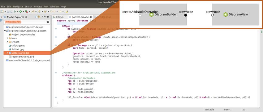
Figure 8: Modeling Architectural Constraints for JetUML in FACT UM Studio
5.1 Case Study: Business Application Systems
Study context. As a study object in the first case study in the field of Business Application Systems, we
chose JetUML [28], an open-source Java application to model UML diagrams. Its main features consist
of creating new diagrams and adding graphical elements to it. The system’s implementation consists
of about 35, 653 lines of code, split into 242 classes. Figure 7 shows an excerpt of the architecture of
JetUML concerned with the drawing of elements.
Study execution. We executed the study in a controlled setting. We where interested in the parts
of the architecture related with the drawing of elements and formulated 10 different properties of the
form: “Whenever a user adds a new element to the drawing board, a corresponding object is created
and drawn by executing the specific method”. To this end, we formalized the properties in FACT UM
Studio as shown in Fig. 8. We then generated events and LTL-formulæ and we used JavaMOP to create
corresponding monitors and AspectJ code instrumentations. Finally, we installed the instrumentation,
started the monitors, and observed them for violations of the architecture constraints.
Findings. During the experiments, we could not find any violations of the 10 assertions specified
for this case study. Thus, we then strengthened the properties to require elements to be drawn only
once. While executing this experiment, the monitors signaled violations of properties. Namely, after14 Detecting Architectural Erosion using RV
Figure 9: Architecture of the Battery Management system
creating the corresponding objects, they were drawn multiple times. While this is not a severe bug, it can
indeed be considered as a design issue, since it involves unnecessary computation which might decrease
performance.
5.2 Case Study: Embedded Systems
Study context. The second case study was executed in collaboration with an industrial partner from the
automotive domain. In this use case we analyzed the architecture of the Service Disconnect (SD) soft-
ware component in the Battery Management System (BMS) in the vehicles. The system is responsible
for monitoring and regulating a car’s battery. Figure 9 depicts the simplified form of the BMC architec-
ture provided by the partner and contains the following components:
Component Vehicle is an abstraction of the car itself.
Analog to digital converter (ADC) forwards the signal to component BMC Master. The ADC pin can
additionally be used for checking the service disconnect status.
Battery disconnect unit (BDU) monitors the connection of the car to its battery. It communicates the
status to BMC Master via the CAN bus.
BMC Master is the actual battery management component which provides a functionality “Service Dis-
connect” which communicates the connection state of the battery to the vehicle. To this end, it compares
the values obtained from ADC and BDU. For the case that the values are the same, it forwards it to
the car. If the two signals differ from each other, then BMC Master should send an error message. In
BMC Master reside all battery management related software features. One of those features is SD whose
dynamic properties we verify at runtime.
Study execution. In contrast to the first case study, this study was executed in an industrial setting in
collaboration with an industrial partner. We where interested in analyzing the following constraint for
the architecture: “The Battery is signaled to be disconnected only if BDU signals disconnect and ADC
signals disconnect”. Again, we first formalized the property in FACT UM Studio (Fig. 10) and generated
events and LTL-formulæ. This time, however, code instrumentation was done using CAPL script. The
log communication from the components’ signals was obtained through CANoe tool. The monitor was
written in C# and created using LTL3 tools [1]. Finally, the system was tested, and the collected log-files
were inspected using the previously created monitor.
Findings. In this case study we specified four properties in total and our experiments revealed runs
of the system in which the architecture property was indeed violated. After communicating our resultsD. Marmsoler and A. Petrovska 15
Figure 10: Modeling Architectural Constraints for Battery Management System in FACT UM Studio.
to our industry partner, they confirmed that the architecture specification was wrong. The reason was
indeed a so-called architectural erosion: Over time, the system was adapted and communication over
the ADC connector was replaced with a direct communication over the CAN bus. However, this is not
reflected in the architecture, which still shows the original connection through the ADC connector.
6 Related Work
In this paper, we provide a systematic approach that detects architectural erosion or architectural drift
based on runtime verification2 . Although different techniques for controlling software architectural
erosion have been proposed across the literature, previous work has mainly focused on static analysis
methods. In this paper, instead of applying static analysis, we present a new approach for solving the
architectural erosion problem by applying runtime verification. This allows us to go beyond detecting
static violations of the systems, but rather focusing and checking dynamic violations that are emerging
from the architectural dynamicity of the systems. Additionally, dynamic software analysis approaches
or runtime verification is vastly used to solve various problems in many different fields. However, until
now it has not been applied to ensure architecture consistency. We believe that our approach is the first
one which combines and utilizes RV for the analysis of dynamic architectural drift. Therefore, in this
section, we discuss related work on the field of architectural erosion and runtime verification.
Murphy at al. [26], Koschke and Simon [16] and Said et al. [30] propose reflection model techniques
as architectural solutions for controlling the software erosion. The reflection model techniques compares
a model of the implemented architecture and a hypothetical model of the intended architecture. The latter
is created from a static analysis of the source code.
Lavery and Watanabe in [18] present a runtime monitoring method for actor-based programs and
a scala-based asynchronous runtime-monitoring module that realizes the proposed method. They aim
2 In this paper the difference between architectural erosion and architectural drift is not considered.16 Detecting Architectural Erosion using RV
to provide failure recovery and mitigation mechanism for Scala applications by making use of the
lightweight software to monitor the properties specified. The module does not require specialized lan-
guages for describing application properties that need to be monitored. The programmer specifies in
Scala the property that needs to be verified, and the mitigation code that needs to be invoked when a
particular property is violated.
To make dynamic reconfigurations more reliable, Léger et al. [19] proposes an approach ensuring that
system consistency and availability is maintained despite run-time failures and changes in the system.
A reconfiguration is a modification of a system state during its execution, and it may potentially put
this system in an inconsistent state. In the first step the authors provide a model of configurations and
reconfigurations. They specify consistency by means of integrity constraints, i.e. configuration invariants
and pre/post-conditions on reconfiguration operations. Alloy has been used as a specification language
to model these constraints, which are later translated in FPath, a navigation language used as a constraint
language in Fractal architectures to check the validity of integrity constraints on real systems at runtime.
7 Conclusion
In this paper, we present an approach that provides a solution to the problem of detecting architectural
erosion for dynamic architectures. To this end, architectural constraints are formally specified using
FACT UM, a language for the specification of constraints for dynamic architectures, and then system-
atically transferred to corresponding monitors and code instrumentation which can be used to detect
violations at runtime.
In the paper, we describe the approach and demonstrate its applicability through a running example.
Next, we describe two algorithms which can be used to generate code instrumentations and monitors,
which monitor the architectural violations from the FACT UM specification. Finally, we describe the
outcome of two case studies on which we evaluated the proposed approach in the context of an open
source Java application and a proprietary C application.
Our results suggest that runtime verification is indeed feasible to detect architectural erosion for
different types of applications: from embedded C applications to object-oriented business information
systems. Additionally, our evaluations of the approach that we propose in this paper show that it scales
well and has the potential to uncover important architecture violations.
However, our results also expose some limitations of the approach. First, our approach can only be
used to detect violations and not to guarantee the absence of architectural violations, nor to act when-
ever an incorrect behavior is detected. Second, it is not yet possible to analyze real-time requirements.
This posed a serious limitation, particularly for the second use case, since many important architectural
assertions require timed aspects.
The first limitation is a general limitation of runtime verification, and there is not much we can do
about this. However, the second limitation can be addressed in the future, as future work. To this end,
future work should focus to extend the approach with timing aspects.
Acknowledgements. We want to thank Ilias Gerostathopoulos for helpful discussions on architectural
erosion. Parts of the work on which we report in this paper was funded by the German Federal Ministry
of Education and Research (BMBF) under grant no. 01Is16043A.D. Marmsoler and A. Petrovska 17
References
[1] Bauer, A.: Ltl3 tools (2019), http://ltl3tools.sourceforge.net/
[2] Bauer, A., Leucker, M., Schallhart, C.: Model-based runtime analysis of distributed reactive systems. In:
Software Engineering Conference, 2006. Australian. pp. 10–pp. IEEE (2006)
[3] Bauer, A., Leucker, M., Schallhart, C.: Monitoring of real-time properties. In: International Conference on
Foundations of Software Technology and Theoretical Computer Science. pp. 260–272. Springer (2006)
[4] Bauer, A., Leucker, M., Schallhart, C.: Runtime verification for ltl and tltl. ACM Transactions on Software
Engineering and Methodology (TOSEM) 20(4), 14 (2011)
[5] Broy, M.: Algebraic specification of reactive systems. In: Algebraic Methodology and Software Technology.
pp. 487–503. Springer, Springer Berlin Heidelberg (1996)
[6] Chen, F., Roşu, G.: Java-mop: A monitoring oriented programming environment for java. In: International
Conference on Tools and Algorithms for the Construction and Analysis of Systems. pp. 546–550. Springer
(2005)
[7] Chen, F., Roşu, G.: Mop: an efficient and generic runtime verification framework. In: Acm Sigplan Notices.
vol. 42, pp. 569–588. ACM (2007)
[8] Clarke, E., Grumberg, O., Peled, D.A.: Model checking the mit press. Cambridge, Massachusetts, London,
UK (1999)
[9] Coverity: Architecture analysis (2019), http://www.coverity.com/products/
architectureanalysis
[10] Deissenboeck, F., Heinemann, L., Hummel, B., Jürgens, E.: Flexible architecture conformance assessment
with conqat. In: Proceedings of the 32nd ACM/IEEE International Conference on Software Engineering -
Volume 2, ICSE 2010, Cape Town, South Africa, 1-8 May 2010. pp. 247–250 (2010), https://doi.org/
10.1145/1810295.1810343
[11] Eick, S.G., Graves, T.L., Karr, A.F., Marron, J.S., Mockus, A.: Does code decay? assessing the evidence
from change management data. IEEE Transactions on Software Engineering 27(1), 1–12 (Jan 2001)
[12] Emerson, E.A.: The beginning of model checking: A personal perspective. In: 25 Years of Model Checking,
pp. 27–45. Springer (2008)
[13] Garlan, D., Allen, R., Ockerbloom, J.: Architectural mismatch: Why reuse is so hard. IEEE Softw. 12(6),
17–26 (Nov 1995), https://doi.org/10.1109/52.469757
[14] Godfrey, M.W., Lee, E.H.S.: Secrets from the monster: Extracting mozilla’s software architecture. In: In
Proc. of 2000 Intl. Symposium on Constructing software engineering tools (CoSET 2000. pp. 15–23 (2000)
[15] Klocwork: Klockwork architect (2019), http://www.klocwork.com/products/insight/
architect-code-visualization/
[16] Koschke, R., Simon, D.: Hierarchical reflexion models. In: null. p. 36. IEEE (2003)
[17] Lattix: The lattix architecture management system (2019), http://www.lattix.com/products
[18] Lavery, P., Watanabe, T.: An actor-based runtime monitoring system for web and desktop applications. In:
2017 18th IEEE/ACIS International Conference on Software Engineering, Artificial Intelligence, Networking
and Parallel/Distributed Computing (SNPD). pp. 385–390 (June 2017)
[19] Léger, M., Ledoux, T., Coupaye, T.: Reliable dynamic reconfigurations in a reflective component model. In:
International Symposium on Component-Based Software Engineering. pp. 74–92. Springer (2010)
[20] Leucker, M., Schallhart, C.: A brief account of runtime verification. The Journal of Logic and Algebraic
Programming 78(5), 293–303 (2009)
[21] Marmsoler, D., Gleirscher, M.: On activation, connection, and behavior in dynamic architectures. Scientific
Annals of Computer Science 26(2), 187–248 (2016)18 Detecting Architectural Erosion using RV
[22] Marmsoler, D.: Hierarchical specication and verication of architecture design patterns. In: Fundamental Ap-
proaches to Software Engineering - 21th International Conference, FASE 2018, Held as Part of the European
Joint Conferences on Theory and Practice of Software, ETAPS 2018, Thessaloniki, Greece, April 14-20,
2018, Proceedings (2018)
[23] Marmsoler, D.: Axiomatic Specification and Interactive Verification of Architectural Design Patterns in FAC-
Tum. Dissertation, Technische Universität München, München (2019)
[24] Marmsoler, D., Gidey, H.K.: FACT UM Studio: A tool for the axiomatic specification and verification of
architectural design patterns. In: Formal Aspects of Component Software - FACS 2018 - 15th International
Conference, Proceedings (2018)
[25] Marmsoler, D., Gleirscher, M.: Specifying properties of dynamic architectures using configuration traces. In:
International Colloquium on Theoretical Aspects of Computing, pp. 235–254. Springer (2016)
[26] Murphy, G.C., Notkin, D., Sullivan, K.: Software reflexion models: Bridging the gap between source and
high-level models. ACM SIGSOFT Software Engineering Notes 20(4), 18–28 (1995)
[27] Pnueli, A.: The temporal logic of programs. In: Foundations of Computer Science, 1977., 18th Annual
Symposium on. pp. 46–57. IEEE (1977)
[28] Robillard, M.: Jetuml (2019), https://github.com/prmr/JetUML
[29] Runtimeverification: Javamop (2019), https://github.com/runtimeverification/javamop
[30] Said, W., Quante, J., Koschke, R.: Reflexion models for state machine extraction and verification. In: 2018
IEEE International Conference on Software Maintenance and Evolution (ICSME). pp. 149–159. IEEE (2018)
[31] Sonargraph: Sonargraph-architect (2019), http://www.hello2morrow.com/products/sonargraph
[32] structure101: (2019), https://structure101.com/
[33] Wirsing, M.: Algebraic specification. In: van Leeuwen, J. (ed.) Handbook of Theoretical Computer Science
(Vol. B), pp. 675–788. MIT Press, Cambridge, MA, USA (1990), http://dl.acm.org/citation.cfm?
id=114891.114904You can also read