PUMPDRIVE 2 / PUMPDRIVE 2 ECO TYPE SERIES BOOKLET - SELF-COOLING, MOTOR-INDEPENDENT FREQUENCY INVERTER - KSB WEB-SHOP
←
→
Page content transcription
If your browser does not render page correctly, please read the page content below
Self-cooling, Motor-independent
Frequency Inverter

PumpDrive 2 /
PumpDrive 2 Eco

Type Series Booklet
Legal information/Copyright
Type Series Booklet PumpDrive 2 / PumpDrive 2 Eco

All rights reserved. The contents provided herein must neither be distributed, copied, reproduced,
edited or processed for any other purpose, nor otherwise transmitted, published or made available to a
third party without the manufacturer's express written consent.
Subject to technical modification without prior notice.

© KSB SE & Co. KGaA, Frankenthal 04/11/2020
Contents

Contents
Pump Control Systems...................................................................................................................................... 4
    Variable Speed Systems ............................................................................................................................................................. 4
       PumpDrive 2 / PumpDrive 2 Eco .......................................................................................................................................... 4
           Main applications........................................................................................................................................................... 4
           General description........................................................................................................................................................ 4
           Designation .................................................................................................................................................................... 4
           Materials ......................................................................................................................................................................... 6
           Power range and sizes ................................................................................................................................................... 6
           Mounting options .......................................................................................................................................................... 7
           Applications.................................................................................................................................................................... 7
           Technical data ................................................................................................................................................................ 7
           PumpDrive 2, motor-mounted / wall-mounted / cabinet-mounted models (enclosure IP55) ................................... 9
           PumpDrive 2 Eco, motor-mounted / wall-mounted / cabinet-mounted models (enclosure IP55) .......................... 10
           Optional components .................................................................................................................................................. 10
           Functions....................................................................................................................................................................... 12
           Control panel................................................................................................................................................................ 15
           Dimensions and weights.............................................................................................................................................. 15
           Project planning information...................................................................................................................................... 18
           Accessories .................................................................................................................................................................... 23
       PumpMeter......................................................................................................................................................................... 35
           General description...................................................................................................................................................... 35
           Main applications......................................................................................................................................................... 35
           Technical data .............................................................................................................................................................. 35
           Materials ....................................................................................................................................................................... 36
           Product benefits ........................................................................................................................................................... 36
           Functions....................................................................................................................................................................... 36
           Design variants ............................................................................................................................................................. 38
           Electrical connections................................................................................................................................................... 38
           PumpMeter................................................................................................................................................................... 38

                                                                                                                                                                                              3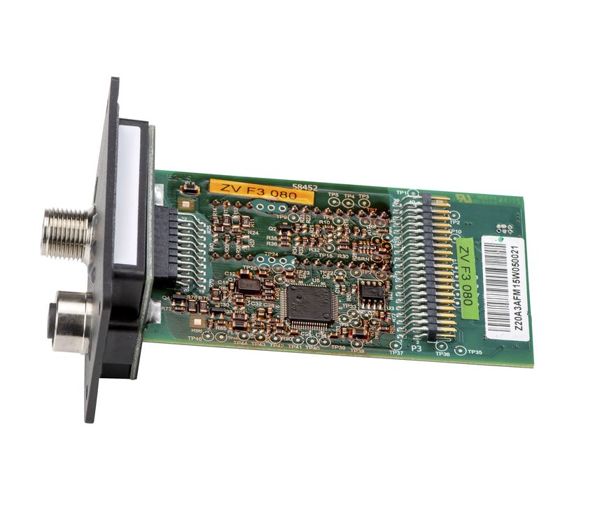
Pump Control Systems
                                                                                                                                   Variable Speed Systems

Pump Control Systems                                                                    Main applications

Variable Speed Systems                                                                  PumpDrive 2
                                                                                         ▪ Air-conditioning systems
                                                                                         ▪ Heat generation / heat distribution
PumpDrive 2 / PumpDrive 2                                                                ▪ Water supply systems
Eco                                                                                      ▪ Water extraction / water withdrawal
                                                                                         ▪ Water treatment / water conditioning
                                                                                         ▪ Water distribution / water transport
                                                                                         ▪ Refrigeration / cooling distribution
                                                                                         ▪ Heat generation / heat distribution
                                                                                         ▪ Fluid transport
                                                                                         ▪ Cooling lubricant distribution
                                                                                         ▪ Service water supply
                                                                                         ▪ Tank drainage
                                                                                         ▪ Waste water transport

                                                                                        PumpDrive 2 Eco
                                                                                         ▪ Air-conditioning systems
                                                                                         ▪ Heat generation / heat distribution
                                                                                         ▪ Water supply systems

                                                                                        General description
                                                                                        Modular self-cooling frequency inverter that enables
                                                                                        continuously variable speed control of asynchronous and
                                                                                        synchronous reluctance motors by means of analog standard
                                                                                        signals, a field bus or the control panel. As PumpDrive is self-
                                                                                        cooling, it can be mounted on a motor, on the wall or in a
                                                                                        control cabinet. Up to six pumps can be controlled without
                                                                                        needing an additional controller.

Designation
Designation example
                                                                                 Position
    1   2   3   4   5   6   7   8   9       10   11   12   13    14   15    16     17    18     19   20   21   22   23   24   25    26              27             28             29             30
    P   D R     V   2   I   -   0   1       1    K    0    0     M    _     K      S        U   P    B    E    5    P    2    _      O                  O            O            O                  O

Designation key
                                                                                                                                                            PumpDrive 2 Eco

Position                                Code                           Description
                                                                                                                                     MyFlow Drive

                                                                                                                                                                                   PumpDrive 2

1-5                                     Product generation
                                        PDRV2                          PumpDrive 2                                                                  ✘                         ✘                  ✘
6                                       Design
                                        E                              PumpDrive 2 Eco                                                              -                         ✘                  -
                                                                                                                                                                                                         4074.5/06-EN

                                        I                              MyFlow Drive                                                                 ✘                         -                  -
                                        -                              PumpDrive 2                                                                  -                         -                  ✘
7                                       Product certifications
                                        -                              CE                                                                     ✘1)                             ✘                  -
                                        R                              UR and CE                                                              ✘2)                             -                  ✘

1       Available only for sizes ≤ 11 kW
2       Available only for sizes 15 kW to 45 kW

4               PumpDrive 2 / PumpDrive 2 Eco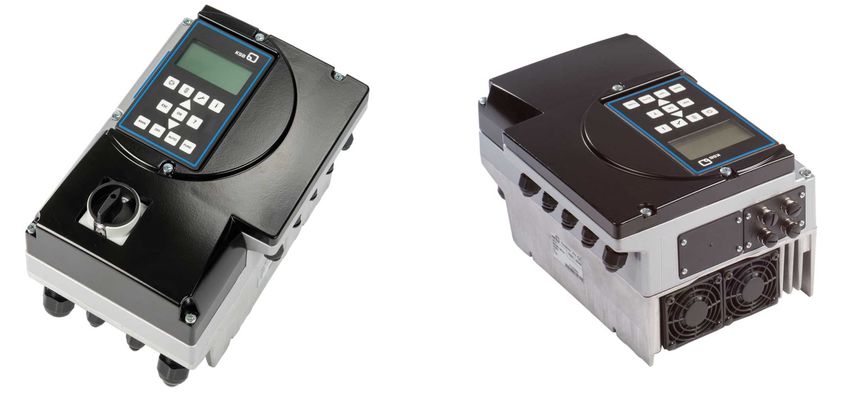
Pump Control Systems
Variable Speed Systems
PumpDrive 2 Eco
Position Code Description
MyFlow Drive
PumpDrive 2
7 L UL and CE - - ✘3)
8-13 Power
A 000K37 = 0,37 kW - ✘ ✘
000K55 = 0,55 kW ✘ ✘ ✘
000K75 = 0,75 kW ✘ ✘ ✘
001K10 = 1,1 kW ✘ ✘ ✘
001K50 = 1,5 kW ✘ ✘ ✘
B 002K20 = 2,2 kW ✘ ✘ ✘
003K00 = 3 kW ✘ ✘ ✘
004K00 = 4 kW ✘ ✘ ✘
C 005K50 = 5,5 kW ✘ ✘ ✘
007K50 = 7,5 kW ✘ ✘ ✘
011K00 = 11 kW ✘ ✘ ✘
D 015K00 = 15 kW ✘ - ✘
018K50 = 18,5 kW ✘ - ✘
022K00 = 22 kW ✘ - ✘
030K00 = 30 kW ✘ - ✘
E 037K00 = 37 kW ✘ - ✘
045K00 = 45 kW ✘ - ✘
055K00 = 55 kW - - ✘
14 Mounting option
M Motor mounting ✘ ✘ ✘
W Wall mounting - ✘ ✘
C Cabinet mounting - ✘ ✘
16 Motor manufacturer
K KSB ✘ ✘ ✘
S Siemens - ✘ ✘
C Cantoni - ✘ ✘
W Wonder - ✘ ✘
17-20 Motor type
1LE1 Siemens 1LE1/ KSB 1PC3 - ✘ ✘
1LA7 Siemens 1LA7/ KSB 1LA7 - ✘ ✘
1LA9 Siemens 1LA9/ KSB 1LA9 - ✘ ✘
1LG6 Siemens 1LG6/ KSB 1LG6 - ✘ ✘
SUPB KSB SuPremE B ✘ ✘ ✘
DMC KSB(DM) Cantoni - ✘ ✘
DMW KSB(DM) Wonder - ✘ ✘
21-22 Efficiency class
E1 IE1 - ✘ ✘
E2 IE2 - ✘ ✘
E3 IE3 - ✘ ✘
E4 IE4 ✘ ✘ ✘
E5 IE5 ✘ ✘ ✘
23-24 Number of motor poles
P2 2 poles ✘ ✘ ✘
P4 4 poles ✘ ✘ ✘
4074.5/06-EN
P6 6 poles - ✘ ✘
26 M12 module
O None ✘ ✘ ✘
M M12 module - ✘ ✘
27 Field bus module
O None ✘ ✘ ✘
L LON - - ✘
3 Available on request only
PumpDrive 2 / PumpDrive 2 Eco 5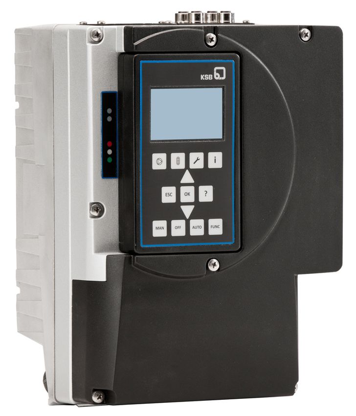
Pump Control Systems
                                                                                                        Variable Speed Systems

                                                                                                                               PumpDrive 2 Eco
Position                    Code                         Description

                                                                                                            MyFlow Drive

                                                                                                                                                     PumpDrive 2
27                          P                            Profibus DP                                                       -                     -                 ✘
                            M                            Modbus RTU                                                  ✘4)                         ✘                 ✘
                            B                            BACnet MS / TP                                                    -                     ✘                 ✘
                            N                            Profinet                                                          -                     ✘                 ✘
28                          Optional component 1
                            O                            None                                                              ✘                     ✘                 ✘
                            I                            I/O extension board                                               -                     -                 ✘
29                          Optional component 2
                            O                            None                                                              ✘                     ✘                 ✘
                            R                            Bluetooth module                                                  -                     ✘                 ✘
30                          Optional component 3
                            O                            None                                                              ✘                     ✘                 ✘
                            M                            Master switch                                                     -                     -                 ✘

Materials
Housing materials

Description                               PumpDrive 2                                PumpDrive 2 Eco
Housing cover                             Die-cast aluminium                         Polyamide, glass-fibre reinforced
Control panel                             Polyamide, glass-fibre reinforced          Polyamide, glass-fibre reinforced
Heat sink                                 Die-cast aluminium                         Die-cast aluminium
Slot covers                               Polyamide, glass-fibre reinforced          Polyamide, glass-fibre reinforced
Cable glands                              Polyamide                                  Polyamide

The parts of the frequency inverter housing which are in contact with the atmosphere are free from paint-wetting impairment
substances.

Power range and sizes

Power range5) for 2-pole (3000 rpm), 4-pole (1500 rpm) and 6-pole (1000 rpm) asynchronous motors and KSB SuPremE

      Size             Nominal electrical power                 Nominal output current               Mains input current
                                   [kW]                                   [A]                                       [A]
        A                          0,37                                    1,3                                 1,5
                                   0,55                                    1,8                                  2
                                   0,75                                    2,5                                 2,7
                                   1,10                                    3,5                                 3,7
                                   1,50                                    4,9                                 5,2
        B                           2,2                                     6                                  6,3
                                    3,0                                     8                                  8,4
                                    4,0                                    10                                 10,4
        C                           5,5                                    14                                 14,6
                                    7,5                                    18                                 18,7
                                    11                                     25                                 25,9
        D                           15                                    34,5                                35,7
                                   18,5                                    44                                 45,4
                                                                                                                                                                       4074.5/06-EN

                                    22                                     51                                 52,4
                                    30                                     68                                 69,7
        E                           37                                     84                                 85,9
                                    45                                    101                                103,1
                                    55                                    120                                122,4

4    Consult the manufacturer.
5    The power ranges specified apply in full to all mounting options.

6           PumpDrive 2 / PumpDrive 2 Eco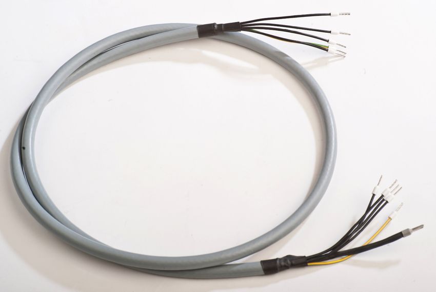
Pump Control Systems
                                                                                                                            Variable Speed Systems

               Mounting options                                                        Motor mounting: The frequency inverter is mounted to the
                                                                                       motor with an adapter or to the pump for the Movitec
               The frequency inverter is identical in design and configuration         configuration. Adapters for subsequent conversion to the
               for all 3 mounting options. PumpDrive 2 can be motor-                   motor mounting configuration for existing pump systems are
               mounted for the entire power range from 0.37 kW to 55 kW.               available as accessories.
                                                                                       Wall / control cabinet mounting: Installation kits for
                                                                                       subsequent conversion to the wall / control cabinet mounting
                                                                                       configuration for existing pump systems are available as
                                                                                       accessories.

               Applications
               Possible combinations of pump and frequency inverter
               Pump              Motor manufacturer                   Motor-mounted model           Wall-mounted model       Cabinet-mounted model
                                                                     (with suitable adapters)
               Amarex KRT        KSB                                             -                           ✘                          ✘
               Etaline            ▪ KSB SuPremE B2/C2 motor IE4/                 ✘                           ✘                          ✘
               Etaline-R            IE5                                          ✘                           ✘                          ✘
               Etaline Z          ▪ Siemens motor, IE2, IE3                      ✘                           ✘                          ✘
               Etabloc                                                           ✘                           ✘                          ✘
               Etanorm                                                           ✘                           ✘                          ✘
               Etachrom                                                          ✘                           ✘                          ✘
               HPK-L                                                             ✘                           ✘                          ✘
               MegaCPK                                                           ✘                           ✘                          ✘
               Multitec                                                          ✘                           ✘                          ✘
               Omega                                                             ✘                           ✘                          ✘
               Sewatec                                                           ✘                           ✘                          ✘
               Sewabloc                                                          -                           ✘                          ✘
               Vitachrom                                                         ✘                           ✘                          ✘
               Movitec           KSB (DM)                                        ✘6)                         ✘                          ✘
                                  ▪ Cantoni motor
                                  ▪ Wonder motor (up to 7.5 kW)
                                  ▪ Siemens motor (11 kW and
                                     above with thrust bearing
                                     housing), IE2, IE3
               UPA               KSB                                              -                          ✘                          ✘

               Motor-independent frequency inverter
               Motor manufacturer            Motor-mounted model (with suitable adapters)           Wall-mounted model       Cabinet-mounted model
               Supplier-neutral7)            Mounted on the motor on request as it must be                   ✘                          ✘
                                            checked whether the available motor adapters fit.

               Technical data
               Technical data

               Characteristic                                                              PumpDrive 2 Eco                        PumpDrive 2
               Mains supply
               Mains voltage8)                                                   1~: 230 V AC +/- 15 % (0.55 and       3 ~ 380 V alternating current
                                                                                              1.1 kW)                  -10 % to 480 V alternating
                                                                                 3 ~: 380 V AC -10 % to 480 V AC       current +10 %
                                                                                      +10 % (0.37 to 11.0 kW)
               Voltage difference between the three phases                                          ±2 % of the supply voltage
               Mains frequency                                                                           50 - 60 Hz ± 2 %
               Mains types                                                             TN-S, TN-CS, TN-C, TT and IT mains (to IEC/EN 60364)
4074.5/06-EN

               Output data
               Frequency inverter output frequency                                                0 - 70 Hz for asynchronous motors
                                                                                                      0 - 140 Hz for KSB SuPremE
               PWM carrier frequency                                                                        Range: 2 - 8 kHz
                                                                                                       (Factory setting: 4 kHz)

               6   Frequency inverter is mounted on pump flange.
               7   Standard asynchronous motors to IEC 60072/ IEC 60034. (The motor used must be suitable for use with a frequency inverter).
               8   If the mains voltage is low, the nominal torque of the motor will be lower.

                                                                                                     PumpDrive 2 / PumpDrive 2 Eco                    7
Pump Control Systems
                                                                                                           Variable Speed Systems

Characteristic                                                           PumpDrive 2 Eco                       PumpDrive 2
Phase rate of rise dv/dt9)                                        5000 V/µs maximum, depending on the size of the frequency
                                                                                         inverter
Peak voltages                                                                           2×1,41×Veff
                                                                Electric cables with a high current-carrying capacity can cause the
                                                                            voltage to increase up to double the value.
Frequency inverter data
Efficiency                                                                                98 % - 95 %10)
Noise emissions                                                           Sound pressure level of pump used + 2.5 dB11)
Environment
Enclosure                                                                               IP55 (to EN 60529)
In-service ambient temperature                                                            -10 °C to +50 °C
In-storage ambient temperature                                                            -10 °C to +70 °C
Relative humidity                                                           In service: 5 % to 85 %, non-condensing
                                                                                      Storage: 5 % to 95 %
                                                                                      Transport: 95 % max.
Installation altitude                                          ▪ < 1000 m above MSL, or 1 % power derating per additional
                                                                 100 m
                                                               ▪ Maximum installation altitude 2000 m above MSL
Vibration resistance                                                            16.7 m/s2 max. (to EN 60068-2-64)
                    12)
Fluid temperature                                                                       -90 °C to +140 °C
EMC
Frequency inverter ≤ 11 kW                                    EN 61800-3 C1 / EN 55011 Class B / cable length ≤ 5 m
Frequency inverter > 11 kW                                    EN 61800-3 C2 / EN 55011 Class A, Group 1 / cable length ≤ 50 m
Mains feedback                                                                      Integrated line chokes
Inputs and outputs
Internal power supply unit                                                              24 V ± 10 %
Maximum load                                                        600 mA DC max., short-circuit-proof and overload-proof
Residual ripple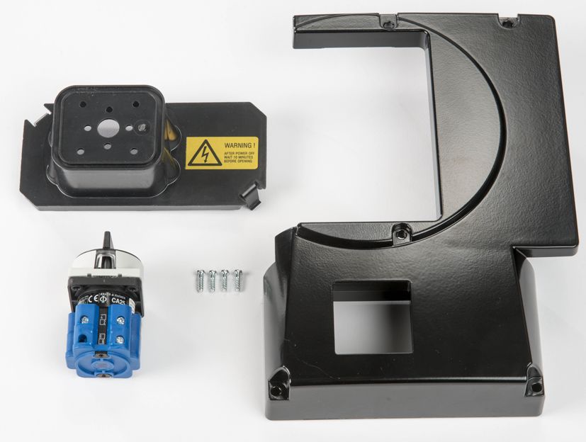
Pump Control Systems
                                                                                                                                            Variable Speed Systems

               Characteristic                                                                        PumpDrive 2 Eco                           PumpDrive 2
               Short-circuit protection and overload protection                                                             Provided
               Digital inputs
               Number of digital inputs                                                       4 in total, 3 of which can be        6 in total, 5 of which can be
                                                                                                     parameterised                        parameterised
               ON level                                                                                                  15...30 V
               OFF level                                                                                                   0...3 V
               Input impedance                                                                                      Approx. 2 kOhm
               Galvanic isolation                                                                         Provided, isolation voltage: 500 V AC
               Delay                                                                                                      < 10 ms
               Reverse polarity protection                                                                               Provided
               Relay outputs
               Number of parameterisable relay outputs                                                 2 NO contacts               2 changeover contacts
               Maximum contact rating                                                                          AC: max. 250 V AC/0.25 A
                                                                                                                 DC: max. 30 V DC/2 A

               PWM carrier frequency
               Power derating for increased carrier frequency
               (at PWM carrier frequency > 4 kHz): INominal motor current (PWM) = INominal motor current × (1 - [fPWM - 4 kHz] × 2.5 %)

               PumpDrive 2, motor-mounted / wall-mounted / cabinet-mounted models (enclosure IP55)
               PumpDrive 2, motor-mounted / wall-mounted / cabinet-mounted models (enclosure IP55)
               Housing type                                                                               PN PumpDrive (parameters not pre-set) + control
                                                                                                             panel (graphical)
                                                                                                      [kW] Mat. No.                                          [kg]13)
               A                                                                                       0,37   01608493                                            5
               A                                                                                       0,55   01608494                                            5
               A                                                                                       0,75   01608495                                            5
               A                                                                                       1,10   01608496                                            5
               A                                                                                       1,50   01608497                                            5
               B                                                                                       2,20 01608498                                            6,5
               B                                                                                       3,00 01608499                                            6,5
               B                                                                                       4,00 01608500                                            6,5
               C                                                                                       5,50 01608501                                           12,6
               C                                                                                       7,50 01608502                                           12,6
               C                                                                                      11,00 01608503                                           12,6
               D                                                                                      15,00   01608504                                         27,6
               D                                                                                      18,50   01608505                                          36
               D                                                                                      22,00   01608506                                          36
               D                                                                                      30,00   01608508                                          36
               E                                                                                      37,00 01608509                                           57,6
               E                                                                                      45,00 01608510                                            60
               E                                                                                      55,00 01608511                                            60

               Optional
                   ▪ M12 module
                   ▪ Profibus DP
                   ▪ LON
                   ▪ BACnet MS / TP
4074.5/06-EN

                   ▪ Profinet
                   ▪ Modbus RTU
                   ▪ Bluetooth module
                   ▪ Integrated master switch
                   ▪ I/O extension board

               13    Without motor adapter

                                                                                                                 PumpDrive 2 / PumpDrive 2 Eco                    9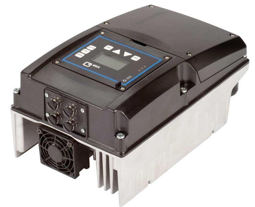
Pump Control Systems
                                                                                                           Variable Speed Systems

PumpDrive 2 Eco, motor-mounted / wall-mounted / cabinet-mounted models (enclosure IP55)
PumpDrive 2 Eco, motor-mounted / wall-mounted / cabinet-mounted models (enclosure IP55)
Housing type                                                                  PN PumpDrive (parameters not pre-set) + control
                                                                                 panel (standard)
                                                                           [kW] Mat. No.                                     [kg]14)
A                                                                           0,37   01608513                                       4
A                                                                           0,55   01608514                                       4
A                                                                           0,75   01608515                                       4
A                                                                           1,10   01608516                                       4
A                                                                           1,50   01608517                                       4
B                                                                           2,20 01608518                                        5,5
B                                                                           3,00 01608519                                        5,5
B                                                                           4,00 01608520                                        5,5
C                                                                           5,50 01608521                                       10,5
C                                                                           7,00 01608522                                       10,5
C                                                                          11,00 01608523                                       10,5

Optional
                        15)
    ▪ M12 module
                       15)
    ▪ Profibus DP
                              15)
    ▪ BACnet MS / TP
                 15)
    ▪ Profinet
                        15)
    ▪ Modbus RTU
    ▪ Bluetooth module

Optional components

                                                                             2                             5
     1

                                                                                   4

                                                         3
                             16)
Fig. 1: PumpDrive 2                optional components
1             Master switch                                         2        M12 module
3             Profibus DP                                           4        Bluetooth module
              LON
              BACnet MS/TP
              Profinet
              Modbus RTU
5             I/O extension board
                                                                                                                                       4074.5/06-EN

14       Without motor adapter
15       PumpDrive 2 Eco has only got one slot. This is where the M12 module or the corresponding field bus module can be inserted.
16       Optional components can be fitted at the factory or retrofitted.

10           PumpDrive 2 / PumpDrive 2 Eco
Pump Control Systems
Variable Speed Systems
1 2
16)
Fig. 2: PumpDrive 2 Eco optional components
1 M12 module 2 Bluetooth module
or
Modbus RTU
Profibus DP
BACnet MS/TP
Profinet
M12 module
▪ Connection of several PumpDrive 2 (for dual-pump configuration / multiple pump configuration) via M12 module
▪ PumpMeter connection to PumpDrive 2 via Modbus using the M12 module
▪ Can be retrofitted
▪ Internal T-connector (bus looped through); uninterruptible even in the event of a frequency inverter power failure
▪ Pre-configured cables (ð Page 23)
Bluetooth module
▪ For communication with a smartphone/tablet (Android or iOS)
▪ Can be retrofitted
▪ Bluetooth 2.0 (range approx. 10 m, compatible from iOS 8)
▪ Installation in control panels of PumpDrive 2 / PumpDrive 2 Eco
17)
Basic functions of the KSB FlowManager app :
▪ Operation and monitoring
▪ Commissioning wizard
▪ Management of data records
▪ Updating software
Field bus module
▪ Field bus modules (plug-in modules) for Profibus DP, Modbus RTU, LON, BACnet MS/TP and Profinet
▪ Can be retrofitted
18)
▪ Internal T-connector (bus looped through), uninterruptible even in the event of a frequency inverter power failure
4074.5/06-EN
17 The KSB FlowManager app is available for download from the App Store and Google Play Store free of charge.
18 This function does not apply when the Profinet module is connected in a bus topology.
PumpDrive 2 / PumpDrive 2 Eco 11Pump Control Systems
Variable Speed Systems
Master switch (optional)
Continuous current, master switch by size
Size Continuous current, master
switch
[A]
A 10
B 16
C 40
D 80
E 160
▪ Can be locked
▪ Retrofit kit comprising master switch, housing components with master switch cutout and installation accessories
▪ Voltage 400 V
I/O extension board (optional)
▪ Installation at the factory or retrofittable as accessory
▪ Installation in the frequency inverter
Additional inputs / outputs:
▪ 1 analog input
▪ 1 analog output
▪ 3 digital inputs
▪ 2 digital outputs
▪ 1 changeover contact relay
▪ 5 NO contact relays
Functions
Overview of functions
Functions / firmware PumpDrive 2 PumpDrive 2 Eco
Protective functions
Thermal motor protection ✘ ✘
Mains voltage monitoring ✘ ✘
Phase failure, motor side ✘ ✘
Short-circuit monitoring, motor side (phase to phase and phase to earth) ✘ ✘
Dynamic overload protection by speed limitation (i2t control) ✘ ✘
Resonant frequency suppression ✘ ✘
Broken wire detection (live zero) ✘ ✘
Protection against dry running and hydraulic blockage (sensorless due to learning ✘ ✘
function)
Dry running protection (external control signal) ✘ ✘
Operating point estimation and characteristic curve control ✘ ✘
Open-loop control
Open-loop control mode ✘ ✘
Closed-loop control
Closed-loop control mode via integrated PID controller ✘ ✘
Pressure control / differential pressure control (∆p const) ✘ ✘
Pressure control / differential pressure control with dynamic pressure compensation ✘ ✘
(∆p var)
4074.5/06-EN
Flow rate control ✘ ✘
Sensorless differential pressure control (∆p const) in a single-pump configuration ✘ ✘
Sensorless differential pressure control with dynamic pressure compensation ✘ ✘
(∆p var) in a single-pump configuration
Sensorless flow rate control ✘ ✘
Level control ✘ ✘
Temperature control ✘ ✘
Alternative setpoint ✘ -
Operation and monitoring (display)
12 PumpDrive 2 / PumpDrive 2 EcoPump Control Systems
Variable Speed Systems
Functions / firmware PumpDrive 2 PumpDrive 2 Eco
Measured value display (pressure, head, speed, electric power, motor voltage, ✘ ✘
motor current, torque)
Fault history ✘ ✘
Operating hours counter ✘ ✘
Fault reporting via relay ✘ ✘
Frequency inverter functions
Programmable start ramps and stop ramps ✘ ✘
Field-oriented control (vector control), V/f control ✘ ✘
Configurable motor control method (asynchronous motor, KSB SuPremE) ✘ ✘
Automatic motor adaptation (AMA) ✘ ✘
Motor standstill heater ✘ ✘
Manual-0-automatic mode ✘ ✘
External OFF ✘ ✘
External minimum speed ✘ ✘
Sleep mode (stand-by mode) ✘ ✘
Energy savings meter ✘ -
Pump functions
Flow rate estimation ✘ ✘
M12 module with PumpMeter bus connection ✘ ✘
M12 module for dual-pump configuration ✘ ✘
M12 module for multiple pump configuration with up to 6 pumps ✘ ✘
Functional check run ✘ ✘
Deragging ✘ ✘
Integrated dual-pump configuration (1×100 % with redundant pump or 2×50 % ✘ ✘
without redundant pump)
Multiple pump configuration with up to 6 pumps ✘ ✘
Waste water function: start-up at maximum speed ✘ -
Waste water function: rinsing function ✘ -
Operation
Control panel ✘ ✘19)
Commissioning wizard ✘ ✘20)
Favourites list ✘ -
Service interface ✘ ✘
Protective functions
Sensorless protection against dry running and hydraulic blockage
Dry running of the pump is detected and the pump set is stopped before components are damaged.
Hydraulic blockage is also detected and initially a warning is displayed. If the blockage persists for a prolonged period of time, the
pump set is stopped. These protective functions do not require sensors. They are based on an automatic learning function which
needs to be run once during commissioning.
Dynamic overload protection by speed limitation (I2t control)
The frequency inverter is equipped with current sensors that record the motor current and enable motor current limitation. When
the defined load limit or temperature limit is reached, the speed is lowered in order to reduce the power (I2t control). The
frequency inverter then no longer operates in closed-loop control mode but maintains the operative function at a lower speed.
Characteristic curve control
The frequency inverter indicates continuous operation outside the permissible range, such as extremely low flow or extreme
overload. The frequency inverter monitors the current operating point on the basis of the motor input power and the speed. In
the case of extremely low flow or overload, a message is output and, depending on the settings, the pump set is switched off as
required.
Open-loop and Closed-loop Control
Sensorless differential pressure control for single-pump configurations
The configurable differential pressure is kept almost constant over a broad operating range without the need for sensors. This can
4074.5/06-EN
also be achieved using the dynamic pressure compensation function. The speed is adjusted as a function of the power input so
that the required differential pressure is maintained.
Dynamic pressure/differential pressure compensation
The dynamic pressure/differential pressure compensation function compensates for pipe friction losses, which need to be
considered if the pressure/differential pressure sensor is installed close to the pump or if sensorless differential pressure control is
used. This ensures a virtually constant pressure/differential pressure at the consumer (e.g. heating) regardless of the flow. The
19 Some functions can only be parameterised and/or displayed using the KSB ServiceTool (see operating manual).
20 Only available via KSB ServiceTool or app
PumpDrive 2 / PumpDrive 2 Eco 13Pump Control Systems
Variable Speed Systems
dynamic pressure compensation function requires signals from two pressure sensors or one differential pressure sensor.
Alternatively, sensorless dynamic differential pressure compensation can be used. The differential pressure setpoint is increased as
a function of the (estimated or measured) flow rate or the speed.
Operation and monitoring
Display
Various physical data, such as the pressure, flow rate, speed, motor voltage, motor current, electric power, torque and others, can
be displayed using the control panel or the service software.
Message history
The last 100 messages of the frequency inverter can be viewed. All messages are provided with a time stamp (real-time clock).
Statistics function
The frequency inverter generates utilisation statistics on the operating hours to date, runtime and number of starts.
Frequency inverter functions
Automatic motor adaptation
Automatic motor adaptation (AMA) is a method for measuring the electric parameters of the motor with the motor at a standstill.
The frequency inverter's motor control method is optimised to ensure optimum motor performance and efficiency.
Motor control method
The frequency inverter's motor control method can be set for either an asynchronous motor or the KSB SuPremE motor.
Stand-by mode (sleep mode)
Sleep mode allows the single or multiple pump system to be started and stopped in line with demand. If sleep mode is activated,
the frequency inverter stops the pump in the case of low flow rates, i.e. when the low flow limit or stop speed is reached. In
pressure control applications, an accumulator can be filled during brief operation with an increased setpoint prior to stopping. If a
drop in pressure and, thus, a flow rate requirement are detected, the pump restarts.
Pump functions
Direct connection to PumpMeter
PumpMeter can be connected to the M12 module of the frequency inverter via the Modbus interface using the M12 connector.
Once they are connected, the frequency inverter and PumpMeter can automatically exchange all the data required for
initialisation (pump characteristic curve, sensor data, etc.). This enables easy and straightforward commissioning, even in retrofit
applications.
Deragging
If fluids with a high solids content are handled, deposits may form that may in turn impair pump operation or prevent start-up of
the pump. The Deragging function serves to prevent deposits from forming in the pump, thus ensuring reliable operation. To this
end, the pump is operated in the opposite direction to its normal direction of rotation at regular intervals in order to clean the
hydraulic system.
Dual-pump configuration
The dual-pump configuration serves to control two pumps of identical design. Two operating modes can be set:
▪ In "1 pump" operating mode, the dual pump system is designed to achieve the setpoint with one pump operating at rated
values (1 x 100 %).
▪ In "2 pumps" operating mode, the system's rated operating point is achieved with both pumps operating at rated values (2 x
50 %).
Both frequency inverters are quickly and easily connected to the respective M12 modules by way of pre-configured cables. The
PumpMeter sensor signal can also be redundantly connected to the second frequency inverter as an option using a pre-configured
"PumpMeter Crosslink" bus cable.
Multiple pump configuration
Up to six PumpDrives can be operated in parallel in a multiple pump configuration. One frequency inverter is used as master and
controls all other available frequency inverters as slaves so that the operating point is as close as possible to the best efficiency
point. If the master fails or malfunctions, the role of master can be assumed by one of the other frequency inverters. This requires,
however, that the appropriate signals be made available in parallel at each frequency inverter. As with dual-pump operation, in a
multiple pump configuration, the frequency inverters are quickly and easily connected to the M12 modules using pre-configured
cables.
Energy-efficient pump starting and stopping
Pumps operated in a dual-pump or multiple pump configuration are started and stopped with a view to optimal efficiency. Based
on the current operating point and the pump characteristic curves, the frequency inverter automatically decides when an
additional pump should be started or stopped to ensure that the multiple pump system is operated as efficiently as possible.
4074.5/06-EN
14 PumpDrive 2 / PumpDrive 2 EcoPump Control Systems
Variable Speed Systems
Control panel
1
3 3
1
2
6
AUTO
4
2 1/min
5
5
ESC OK ?
6
MAN OFF AUTO FUNC
PumpDrive 2: Graphical control panel PumpDrive 2 Eco: Standard control panel
Description of standard control panel
Position Description Function
1 Service interface PumpDrive configuration and parameterisation via PC/notebook.
2 LED traffic light function The traffic light function provides information about the pump system's
operating status.
3 Display PumpDrive 2 Eco: Standard control panel
Display of the operating status, motor speed, setpoint and actual value via
LEDs
PumpDrive 2: Graphical control panel
Display of the operating values, alerts and parameters in different national
languages
4 Menu keys Change to the elements of the first menu level
5 Navigation keys Setpoint specification, parameter selection and confirmation
6 Operating keys Toggling operating modes
Dimensions and weights
PumpDrive 2 Eco
b c d
a e f
4074.5/06-EN
F
Fig. 3: PumpDrive 2 Eco dimensions
PumpDrive 2 / PumpDrive 2 Eco 15Pump Control Systems
Variable Speed Systems
Dimensions and weights
PN Motor-mounted model Wall-mounted/ Fastening screws/bolts [kg]22)
cabinet-mounted model21)
Housing
a b c d e a b c d f F
type
[kW] [mm] -
A 0,37 260 171 144 140 141 343 171 144 140 333 M4 × 10 4
A 0,55 260 171 144 140 141 343 171 144 140 333 M4 × 10 4
A 0,75 260 171 144 140 141 343 171 144 140 333 M4 × 10 4
A 1,10 260 171 144 140 141 343 171 144 140 333 M4 × 10 4
A 1,50 260 171 144 140 141 343 171 144 140 333 M4 × 10 4
B 2,20 290 186 144 155 121 328 186 144 155 318 M4 × 10 5,5
B 3,00 290 186 144 155 121 328 186 144 155 318 M4 × 10 5,5
B 4,00 290 186 144 155 121 328 186 144 155 318 M4 × 10 5,5
C 5,50 330 255 185 219 205 401 255 185 219 387 M6 × 12 10,5
C 7,00 330 255 185 219 205 401 255 185 219 387 M6 × 12 10,5
C 11,00 330 255 185 219 205 401 255 185 219 387 M6 × 12 10,5
PumpDrive 2
c
b d
a e f
F
Fig. 4: PumpDrive 2 dimensions
Dimensions and weights
PN Motor-mounted model Wall-mounted/ Fastening screws/bolts [kg]24)
cabinet-mounted model23)
Housing
a b c d e a b c d f F
type
[kW] [mm] -
A 0,37 260 190 166 140 141 343 190 166 140 333 M4 × 10 5
A 0,55 260 190 166 140 141 343 190 166 140 333 M4 × 10 5
A 0,75 260 190 166 140 141 343 190 166 140 333 M4 × 10 5
A 1,10 260 190 166 140 141 343 190 166 140 333 M4 × 10 5
A 1,50 260 190 166 140 141 343 190 166 140 333 M4 × 10 5
B 2,20 290 211 166 155 121 328 211 166 155 318 M4 × 10 6,5
B 3,00 290 211 166 155 121 328 211 166 155 318 M4 × 10 6,5
B 4,00 290 211 166 155 121 328 211 166 155 318 M4 × 10 6,5
4074.5/06-EN
C 5,50 330 280 210 219 205 401 280 210 219 387 M6 × 12 12,6
C 7,50 330 280 210 219 205 401 280 210 219 387 M6 × 12 12,6
C 11,00 330 280 210 219 205 401 280 210 219 387 M6 × 12 12,6
21 The dimensions provided refer to the frequency inverter including the wall-mounting brackets.
22 Without motor adapter
23 The dimensions provided refer to the frequency inverter including the wall-mounting brackets.
24 Without motor adapter
16 PumpDrive 2 / PumpDrive 2 EcoPump Control Systems
Variable Speed Systems
PN Motor-mounted model Wall-mounted/ Fastening screws/bolts [kg]24)
cabinet-mounted model23)
Housing
a b c d e a b c d f F
type
[kW] [mm] -
D 15,00 460 350 290 280 309 582 350 290 280 565 M8 × 14 27,6
D 18,50 460 350 290 280 309 582 350 290 280 565 M8 × 14 36
D 22,00 460 350 290 280 309 582 350 290 280 565 M8 × 14 36
D 30,00 460 350 290 280 309 582 350 290 280 565 M8 × 14 36
E 37,00 700 455 340 375 475 819 455 340 375 800 M8 × 14 57,6
E 45,00 700 455 340 375 475 819 455 340 375 800 M8 × 14 60
E 55,00 700 455 340 375 475 819 455 340 375 800 M8 × 14 60
4074.5/06-EN
PumpDrive 2 / PumpDrive 2 Eco 17Pump Control Systems
Variable Speed Systems
Project planning information
Power cables
Unshielded cables can be used as power cables.
The power cables must be designed with a cross-section suitable for the nominal mains current.
If a mains contactor is used in the power cable (before the frequency inverter), this must be configured for an AC1 duty rating; the
rated current values of the frequency inverters used are added and the result is increased by 15 %.
Power cable properties
Mains input current25)
power cable
Cable cross-
Size Cable gland for
KSB motor
core cross-
Maximum
section
section
power cable
Power cable [A]
thermistor
Power
Variant for
Sensor
Motor
cable
PTC
[kW] 400 V / 3~ 230 V /1~ [mm²]
A .. 000K37 .. 0,37 M20 M16 M20 M16 1,5 - 2,5 2,5
.. 000K55 .. 0,55 M20 M16 M20 M16 2,0 4,0 2,5 2,5
.. 000K75 .. 0,75 M20 M16 M20 M16 2,7 - 2,5 2,5
..001K10.. 1,1 M20 M16 M20 M16 3,7 6,0 2,5 2,5
.. 001K50 .. 1,5 M25 M16 M25 M16 5,2 - 2,5 2,5
B .. 002K20 .. 2,2 M25 M16 M25 M16 6,3 - 2,5 2,5
.. 003K00 .. 3 M25 M16 M25 M16 8,4 - 2,5 2,5
.. 004K00 .. 4 M25 M16 M25 M16 10,4 - 2,5 2,5
C ..005K500.. 5,5 M32 M16 M32 M16 14,6 - 16 4
..007K500.. 7,5 M32 M16 M32 M16 18,7 - 16 4
..011K000.. 11 M32 M16 M32 M16 25,9 - 16 6
D ..15K000.. 15 M40 M32 M40 M20 35,7 - 50 10
..18K500.. 18,5 M40 M32 M40 M20 45,4 - 50 16
..22K00.. 22 M40 M32 M40 M20 52,4 - 50 16
..30K00.. 30 M40 M32 M40 M20 69,7 - 50 25
E ..37K00.. 37 M63 M32 M63 M20 85,9 - 95 35
..45K00.. 45 M63 M32 M63 M20 103,1 - 95 50
..55K00.. 55 M63 M32 M63 M20 122,4 - 95 70
1 2 3
Fig. 5: Structure of electric cable
1 Wire end sleeve
2 Core
3 Cable
Cable cross-sections of control terminals
Control terminal Core cross-section Cable diameter26)
4074.5/06-EN
Rigid cores Flexible cores Flexible cores with wire
end sleeves
[mm²] [mm]
Terminal strip A, B, C 0,2 - 1,5 0,2 - 1,0 0,25 - 0,75 M12: 3,5 - 7,0
M16: 5,0 - 10,0
25 Observe the information on the use of line chokes provided in the Project planning information and Accessories sections.
26 Impairment of protection provided by enclosure when cable diameters other than those specified are used.
18 PumpDrive 2 / PumpDrive 2 EcoPump Control Systems
Variable Speed Systems
Length of motor power cable
If the frequency inverter is not mounted on the motor to be controlled, longer motor power cables may be required. The stray
capacitance of the connection cables may result in high-frequency discharge currents flowing to ground. The sum of the discharge
currents and motor current may exceed the output-side rated current of the frequency inverter. This will activate the frequency
inverter's protection equipment and the motor will be stopped. The following motor power cables are recommended depending
on the power range:
Length of motor power cable
Power range Cable length Stray capacitance
Max.
[kW] [m] [nF]
≤ 11 (Class B) 5 ≤5
≥ 15 (Class A, Group 1) 50 ≤5
Output filters
Dv/dt output filters can be used in conjunction with an asynchronous motor and a KSB SuPremE motor. Sine filters can only be
used in conjunction with an asynchronous motor. If the length or stray capacitance of the power cable exceed the values
indicated, we recommend installing a suitable output filter between the frequency inverter and the motor to be controlled. These
filters reduce the voltage ramp-up time of the frequency inverter output voltages and limit their peaks. (ð Page 21)
Electrical protection equipment
Cable protection
We recommend installing a miniature circuit breaker or suitable fuses for protecting the power cable of the frequency inverter
with consideration of the input-side rated currents as per the following table. The protection must be able to withstand an
overload current of 1.5 times the input-side rated current for 60 seconds. The fuse can be of type gG (IEC 60269) or a UL-
equivalent with a response time below 0.5 seconds.
If voltage fluctuations are expected in the power supply, we recommend protecting the frequency inverter with fast acting fuses
of type gR (IEC 60269) or UL-class JFHR2/JFHR8. The maximum permissible values for the clearing integral i²t [A²s] indicated in the
following table must be observed. The values for the clearing integral i²t can vary strongly at the same rated power, depending on
the manufacturer. For any deviating values, make sure they are smaller than or equal to the maximum permissible value indicated
in the table.
Technical data of the overcurrent protective device
voltage
Total i²t @ AC 660 V
Size
Rated
Rated current Irms
Clearing integral
IEC 60269-4 UL 248-13 Rated breaking
Variant for
capacity
Power
Ipeak
400 V / 3~ 230 V / 1~ [kW] [A] [V AC] [kA] [A²s] [A]
A .. 000K37 .. ✘ - 0,37 20 690 700 200 168 600
.. 000K55 .. ✘ - 0,55 20 690 700 200 168 600
- ✘ 5,5 500 - 180 6 16
.. 000K75 .. ✘ - 0,75 20 690 700 200 168 600
..001K10.. ✘ - 1,1 20 690 700 200 168 600
- ✘ 8 500 - 180 8 16
.. 001K50 .. ✘ - 1,5 20 690 700 200 168 600
B .. 002K20 .. ✘ - 2,2 20 690 700 200 168 600
.. 003K00 .. ✘ - 3 20 690 700 200 168 600
.. 004K00 .. ✘ - 4 20 690 700 200 168 600
C ..005K500.. ✘ - 5,5 50 690 700 200 945 1500
..007K500.. ✘ - 7,5 50 690 700 200 945 1500
..011K000.. ✘ - 11 50 690 700 200 945 1500
D ..15K000.. ✘ - 15 100 690 700 200 6319 2600
4074.5/06-EN
..18K500.. ✘ - 18,5 100 690 700 200 6319 2600
..22K00.. ✘ - 22 100 690 700 200 6319 2600
..30K00.. ✘ - 30 100 690 700 200 6319 2600
E ..37K00.. ✘ - 37 160 690 700 200 5775 2100
..45K00.. ✘ - 45 160 690 700 200 5775 2100
..55K00.. ✘ - 55 160 690 700 200 5775 2100
PumpDrive 2 / PumpDrive 2 Eco 19Pump Control Systems
Variable Speed Systems
Motor protection switch
Separate motor protection is not required because the frequency inverter has its own safety devices (e.g. electronic overcurrent
trip). Available motor protection switches must be rated for 1.4 times the nominal motor current.
Residual current device
If fixed connections and appropriate supplementary earthing are used (to DIN VDE 0160), RCDs are not mandatory for frequency
inverters.
If residual current devices (RCDs) are used, three-phase frequency inverters must in accordance with DIN VDE 0160 be connected
via universal AC/DC sensitive residual current devices (RCDs), as potential direct-current components may cause standard AC
sensitive RCDs to either fail to respond or respond erroneously.
Residual current device to be selected
Size Rated current [mA]
A, B and C 150
D and E 300
If you are using a long shielded cable for the mains connection / motor connection, the residual-current monitoring device may be
triggered by the discharge current that flows to earth (triggered by the carrier frequency). Remedies: Replace the RCD (residual
current device) or lower the response limit.
Compensation systems
If the frequency inverter is operated on power supply networks with compensation systems, these systems must be designed by
the manufacturer for operation in conjunction with a frequency inverter.
Information on electromagnetic compatibility If you cannot avoid crossing control and mains power/motor
power cables, you should cross them at 90 degrees to each
Electromagnetic interference from other electrical devices can other.
affect the frequency inverter. Interference can also be emitted
by the frequency inverter itself, however.
The interference emitted by the frequency inverter is generally Earth connection
conducted through the motor power cables. The following
measures are proposed for RFI suppression: The frequency inverter must be properly earthed.
▪ Shielded motor power cables for line lengths > 70 cm To ensure greater interference immunity, a wide contact face is
(especially recommended for frequency inverters with low required for the different earth connections.
power ratings) In the case of cabinet mounting, use two separate copper
▪ Made from a single piece of formed metal cable ducting earth bus bars (mains power connection / motor connection
with a minimum coverage of 80 % (if shielded connection and control connection bar) with a suitable size and cross-
cables cannot be used) section for earthing the frequency inverter. All the earth
connections are connected to these.
Use different earth bus bars for the control cable and mains
power/motor power cables. The bars are connected to the earthing system at one point
only.
The shield on the power cable/connection cable must consist of
a single piece and be earthed at both ends either just on the The control cabinet is earthed via the mains earthing system.
appropriate earth terminal or on the earth bus bar (do not
connect it to the earth bus bar in the control cabinet).
Output filter
The shielded cable ensures that the high-frequency current,
which normally flows as a discharge current from the motor R
L1
housing to earth or between the individual conductors, flows L2
through the shielding. L3
L CX
The shield for the control cable (connection on the frequency CY R'
inverter side only) also serves as protection against radiated PE
emission. Fig. 6: Installing line choke and output filters
If using shielded cables, use a wide contact face for the Transformer R
Dv/dt output filters
different earth connections to ensure greater interference L CX
(suitable for
immunity. CY R'
PE asynchronous motor
In applications with long shielded motor cables, provide and KSB SuPremE
additional reactive resistors or output filters to compensate the motor)
capacitive stray current to earth and reduce the rate of voltage or
rise on the motor. These measures help reduce radio
interference further. Using just ferrite rings or reactive resistors Sine filter (only suitable
does not ensure compliance with the limit values defined in for asynchronous
the EMC directive. motor)
Line choke Motor
NOTE! If you are using shielded cables that are longer than
4074.5/06-EN
10 m, check the stray capacitance to ensure that the diffusion
between the phases or to earth is not excessive, which could
cause the frequency inverter to stop.
Route control cable and mains power/motor power cables in
separate cable ducts.
When routing the control cable observe a minimum distance of
0.3 metres between the control cable and the mains power/
motor power cables.
20 PumpDrive 2 / PumpDrive 2 EcoPump Control Systems
Variable Speed Systems
The maximum cable lengths must be observed in order to meet Output filters can be used to remedy these situations:
RFI suppression requirements to DIN 55011. Output filters are
When a filter is used, the voltage peak (Vpeak) and its rate of
required if the maximum cable lengths are exceeded.
rise (dv/dt) can be reduced. The peak voltages can also be seen
IGBT switchgear is suitable for achieving high power. This, as a function of the stray capacitance induced by the power
however, can result in faults due to the rapid switching circuits. The stray capacitance must be below 5 nF. If long
operations, particularly if you are using long motor cables / cables are required for installation reasons, for example, for
drive control cables: wall or control cabinet mounting, and the stray capacitance
▪ Electromagnetic interference value exceeds the maximum permissible value, a dv/dt limiting
filter or sine filter must be installed. Connect the filter at the
▪ Damage to the motor winding insulation output of the frequency inverter. The filter protects the
frequency inverter against excessive discharge currents and
▪ Voltage peaks due to high stray capacitance on the cable prevents the protective equipment from being deactivated as a
connections result.
▪ Damage to the short-circuit protective devices
Overview of output filters for PumpDrive 2
Output filters for motor power cables 50 m / 80 m
Nominal output current
Output filter
Frequency inverter
Frequency inverter
dv/dt filter for L B H Mat. No.
power cable length
Nominal current at
Nominal current at
Maximum motor
Maximum motor
KSB SuPremE
Asynchronous
frequency
power
50 °C
40 °C
motors
[kW] [A] [A] [A] 1500 rpm 3000 rpm [Hz] [m] [mm] [mm] [mm] [kg]
0,37 1,3 6,1 - FOVT-008B 140 50 49 85 58 47121240 1,6
0,55 1,8
0,75 2,5
1,1 3,5
1,5 4,9
2,2 6
3 8 12,1 - FOVT-016B 140 50 150 100 56 47121247 2,2
4 10
5,5 14 18,9 - FOVT-025B 140 50 231 119 71 47121248 4,5
7,5 18
11 25 27,3 - FOVT-036B 140 50 350 149 81 47121249 5,8
1534,5 34,5 - FOVT-036B FOVT-036B - 70 50 350 149 81 47121249 5,8
66 - - - FN510-66-34 200 50 470 235 140 47121253 22
18,5 44 50 - FN-510-50-34 FN-510-50-34 - 200 50 470 235 140 47121251 21
22 51 66 - FN-510-66-34 FN-510-66-34 - 200 50 470 235 140 47121253 22
30 68 - 90 RWK-305-90-KL RWK-305-90-KL - 60 80 190 115 225 47121254 7,4
37 85,9
45 101 - 124 RWK-305-124-KS RWK-305-124-KS - 60 80 190 180 160 01665521 7,57
55 120 - 156 RWK 305-156-KS RWK 305-156-KS - 60 80 190 180 160 01665522 9,5
Output filters for motor power cables up to 160 m
Nominal output current
Output filter
Frequency inverter
Frequency inverter
dv/dt filter for L B H Mat. No.
power cable length
Nominal current at
Maximum motor
Maximum motor
KSB SuPremE
Asynchronous
frequency
power
45 °C27)
motors
4074.5/06-EN
[kW] [A] [A] 1500 rpm 3000 rpm [Hz] [m] [mm] [mm] [mm] [kg]
0,37 1,3 8,4 FN 5060-12-84 ≤140 160 125 85,5 104 01686772 1
0,55 1,8
0,75 2,5
1,1 3,5
27 Including derating
PumpDrive 2 / PumpDrive 2 Eco 21Pump Control Systems
Variable Speed Systems
Nominal output current
Output filter
Frequency inverter
Frequency inverter
dv/dt filter for L B H Mat. No.
power cable length
Nominal current at
Maximum motor
Maximum motor
KSB SuPremE
Asynchronous
frequency
power
45 °C27)
motors
[kW] [A] [A] 1500 rpm 3000 rpm [Hz] [m] [mm] [mm] [mm] [kg]
1,5 4,9 8,4 FN 5060-12-84 ≤140 160 125 85,5 104 01686772 1
2,2 6
3 8
4 10 16,8 FN 5060-24-84 ≤140 160 140 96 113 01686773 1,6
5,5 14
7,5 21 18 FN 5060-30-99 ≤140 160 240 109 151 01686774 5,85
11 31,5 25 FN 5060-45-99 ≤140 160 240 110 151 01686775 6,4
15 43,2 34,5 FN 5060-45-99 FN 5060-45-99 - ≤70 160 240 110 151 01686775 6,4
42 - - FN 5060-60-99 ≤140 160 240 110 181 01686776 7
18,5 44 57,6 FN 5060-60-99 - - ≤70 160 240 110 181 01686776 7
49 - - FN 5060-70-99 ≤140 160 240 121 222 01686857 8,52
22 51 57,6 FN 5060-60-99 - - ≤70 160 240 110 181 01686776 7
63 - - FN 5060-90-99 ≤140 160 240 130 221 01686858 10,5
30 68 63 - - FN 5060-90-99 ≤70 160 240 130 221 01686858 10,5
77 - - FN 5060-110-99 ≤140 160 240 136 221 01686859 11,35
37 85,9 86,4 - - FN 5060-90-99 ≤70 160 240 130 221 01686858 10,5
105 - - FN 5060-150-99 ≤140 160 240 141,5 254 01686860 14,47
45 101 105,6 - - FN 5060-110-99 ≤70 160 240 136 221 01686859 11,35
105 - - FN 5060-150-99 ≤140 160 240 141,5 254 01686860 14,47
55 120 144 - - FN 5060-150-99 ≤70 160 240 141,5 254 01686860 14,47
126 - - FN 5060-180-99 ≤140 160 240 142,5 310 01686861 17,3
Line chokes
The line input currents indicated in the selection information are for orientation purposes only; they refer to operation at nominal
rating. These currents may vary depending on the actual line impedance. In low-impedance mains, higher currents may occur. The
input current can be limited by using external line chokes in addition to the integrated line chokes (in the power range up to and
including 45 kW). Line chokes reduce mains feedback and improve the power factor.
Line chokes connected in series in the line to the consumer installation ensure that the required short circuit voltage of 4 % to the
mains is complied with and reduce mains feedback. Mains feedback occurring in the form of harmonics may cause problems in the
public power supply mains. The charge currents of the DC link capacitors can be limited, which will increase the service life of
these primary components. Line chokes reduce the reactive power component and thus improve the effective power factor. The
scope of DIN EN 61000-3-2 must be heeded.
Three-phase line choke:
▪ Enclosure IP00
▪ Thermal class F
▪ Maximum ambient temperature 40 °C
Overview of line chokes for asynchronous motors and SuPremE motors
inductance
Line choke
Size Rating L W H Mat. No.
Maximum
INominal motor
Nominal
current
current
current
Isat
ln
[kW] [mH] [A] [mm] [mm] [mm] [kg]
A ..000K37.. 0,37 7,0 6,0 1,5 In 150 85 155 01665518 3,6
4074.5/06-EN
..000K55.. 0,55
..000K75.. 0,75
..001K10.. 1,1
..001K50.. 1,5
B ..002K20.. 2,2 2,0 11 1,5 In 150 85 150 01093105 3,6
..003K00.. 3
..004K00.. 4
C ..005K50.. 5,5 1,1 28 1,5 In 180 120 178 01093106 8,3
22 PumpDrive 2 / PumpDrive 2 EcoPump Control Systems
Variable Speed Systems
inductance
Line choke
Size Rating L W H Mat. No.
Maximum
INominal motor
Nominal
current
current
current
Isat
ln
[kW] [mH] [A] [mm] [mm] [mm] [kg]
C ..007K50.. 7,5 1,1 28 1,5 In 180 120 178 01093106 8,3
..011K00.. 11
D ..015K00.. 15 0,5 51 1,5 In 180 135 178 01093107 9,17
..018K50.. 18,5
..022K00.. 22 0,1 100 1,5 In 180 180 180 01093108 9,17
..030K00.. 30
E ..037K00.. 37
..045K00.. 45
..055K00.. 55 0,1 125 1,5 In 240 145 190 01665519 14
Accessories
Service software (PumpDrive 2 / PumpDrive 2 Eco)
Accessories: Service software (PumpDrive 2/PumpDrive 2 Eco)
Description Design Mat. No. [kg]
USB parameterisation cable, optical Length 1 m 01538436 0,2
For frequency inverter parameterisation with Automation
service software
Pre-configured with optical connection for frequency inverter
and USB connection for laptop/ PC
Service dongle - 47121256 0,1
For authorisation
The service software can also be used without a dongle.
However, the parameters used for customer service will be
locked in this case.
The dongle can only be used after it has been enabled by KSB
in accordance with the instructions included.
Control panels (PumpDrive 2)
Accessories: PumpDrive 2 control panels
Description Design Mat. No. [kg]
Wall mounting brackets accessories set Wall mounting/ 01522974 0,3
mounting on a pipe
For mounting the graphical control panel of the frequency
inverter
4 brackets and screws
Connection cable for graphical control panel Length 3 m 01522975 0,3
For connecting the graphical control panel separately from the Length 5 m 01566211 0,3
frequency inverter Length 10 m 01566212 0,6
Colour: black, straight connector, angled socket Length 20 m 01566213 1
4074.5/06-EN
Motor mounting adapter (PumpDrive 2 / PumpDrive 2 Eco)
An adapter is required to mount the frequency inverter to the motor. Select the adapter based on the motor size and the type of
construction used.
KSB SuPremE type A (sizes 180 to 225): No motor mounting adapters can be retrofitted for PumpDrive 2 and PumpDrive 2 Eco. The
preferred mounting option is wall mounting.
KSB SuPremE type B1 (size 180 to 225): Adapters for PumpDrive 2/ PumpDrive 2 Eco for motor mounting upon the customer’s
request or if a replacement is needed (replacement of PumpDrive 1 with PumpDrive 2) can be retrofitted.
PumpDrive 2 / PumpDrive 2 Eco 23Pump Control Systems
Variable Speed Systems
KSB SuPremE type B2: Use for new installations with PumpDrive 2 and PumpDrive 2 Eco.
Accessories: Motor mounting adapter (PumpDrive 2 / PumpDrive 2 Eco)
Description Design Mat. No. [kg]
inverter size
P Motor
Frequency
[kW]
Motor adapter kit A 0,37 - 1,5 BG80 01496568 3
For mounting frequency inverter to A 0,37 - 1,5 BG90 01496569 3
KSB motor/ Siemens standardised B 2,2 - 4 BG90 01496570 3
motor, type 1LE1/ 1PC3, 2-pole/ 4-
pole/ 6-pole, IE2/ IE3 B 2,2 - 4 BG100 01496571 3
B 2,2 - 4 BG112 01496572 3,8
With power cable
C 5,5 - 11 BG132 01496573 3,8
C 5,5 - 11 BG160 01496574 3,8
D 15 - 30 BG160 01496575 5,2
D 18,5/22 BG180 M, L 01496576 8
D 30 BG200 L 01496577 10
D 15 - 30 BG225 01654738 11
E 37 BG200 L 01496578 14,2
E 37/45 BG225 S, M 01496579 11
E 37 - 55 BG250 M 01496580 14
E 37 - 55 BG280 S, M 01500521 16
- Motor adapter kit A 0,37 - 1,5 1LA7 BG71M V1 01506318 3
For mounting frequency inverter to A 0,37 - 1,5 1LA9 BG80 V1 01506320 3
KSB motor/ Siemens standardised A 0,37 - 1,5 1LA7 BG80 V1 01506320 3
motor, type 1LA7/ 1LA9/ 1LG6
(retrofit), 2-pole/ 4-pole A 0,37 - 1,5 1LA9 BG90 V1 01506322 3
A 0,37 - 1,5 1LA9 BG90 B3 01606776 3
With power cable
B 2,2 - 4 1LA9 BG90 B3 01506323 3
B 2,2 - 4 1LA9 BG90 V1 01606892 3
B 2,2 - 4 1LA9 BG100 B3 01506324 3
B 2,2 - 4 1LA9 BG100 V15 01606893 3
B 2,2 - 4 1LA7 BG112 B3/V15 01506325 3,8
1LA9 BG112 B3/V15
C 5,5 - 11 1LA9 BG132 B3/V15 01506326 3,8
C 5,5 - 11 1LA9 BG160 B3/V15 01506328 3,8
D 15 - 30 1LA9 BG160 B3/V15 01506329 5,2
D 15 - 30 1LA9 BG180 B3/V15 01506331 8
D 15 - 30 1LA9 BG200 B3/V15 01506332 10
E 37 - 55 1LA9 BG200 B3 01506333 10
E 37 - 55 1LG6 BG225S B3 01506334 11
E 37 - 55 1LG6 BG225M B3 01650429 11
Motor adapter kit A 0,55/0,75/1,1 BG80 M 01666670 3
For mounting frequency inverter to A 1,1/1,5 BG90 S 01666671 3,5
KSB SuPremE A/ SuPremE B1 motor, 2- A 1,5 BG90 L 01677488 3,7
pole/ 4-pole
B 2,2 BG90 L 01666672 3,7
With power cable B 2,2/3 BG100 L 01666673 4
B 4 BG112 M 01666674 4,1
C 5,5/7,5 BG132 S, M 01666675 4,2
C 11 BG160 M 01666677 3,8
D 15 BG160 M 01675995 3,8
4074.5/06-EN
D 15/18,5 BG160 L 01677489 5,2
Motor adapter kit D 18,5/22 BG180 M, L 01496576 8
For mounting frequency inverter to D 30 BG200 L 01496577 10
KSB SuPremE B1 motor, 2-pole/ 4-pole E 37 BG200 L 01496578 14,2
With power cable E 37/45 BG225 S, M 01496579 11
24 PumpDrive 2 / PumpDrive 2 EcoPump Control Systems
Variable Speed Systems
Accessories: Power/connection cable (PumpDrive 2)
Description Design Mat. No. [kg]
Cable connector, shielded ≤ 4 kW: 4 × 2,5² + PTC...XM 01538433 0,9
Blanking plate including screws to replace - 01595759 0,1
removed motor connector
1320
300
220
200
220
200
Motor power cable, shielded ≤ 4 kW: 4 × 2,5 mm² + PTC 47117500 0,3
60 60
Length 0.7 m
M8
For connecting the PTC sensor, halogen-
M8
1200
free, price per unit 5,5 - 7,5 kW: 4 x 4 mm² + PTC 01437169 0,3
940 Length 0.9 m
40 40
M5
11 kW: 4 × 6 mm² + PTC 01637009 0,3
M6 20 120
900
160 20
Length 0.9 m
30
740
30
M4 15 kW: 4 × 10 mm² + PTC 47117506 0,8
Ferrit
M4
Length 0.9 m
4
20 100 100 120 20
M
700 18,5 - 22 kW: 4 × 16 mm² + PTC 01466746 1
Length 1.15 m
30 kW: 4 × 25 mm² + PTC 47117509 1,7
Length 1.2 m
37 kW: 4 × 35 mm² + PTC 01641614 2
Length 1.4 m
45 kW: 4 × 50 mm² + PTC 01641615 2,4
Length 1.5 m
55 kW: 4 × 70 mm² + PTC 01641616 3,3
Length 1.6 m
Accessories: Power cable (PumpDrive 2 Eco)
Description Design Mat. No. [kg]
Cable connector, shielded ≤ 4 kW: 4 × 2,5² + PTC...XM 01538433 0,9
Ferrite core, motor power cable - 47117922 0,3
Blanking plate including screws to replace - 01595759 0,1
removed motor connector
4074.5/06-EN
PumpDrive 2 / PumpDrive 2 Eco 25Pump Control Systems
Variable Speed Systems
Description Design Mat. No. [kg]
1320
300
220
200
220
200
Motor power cable, shielded ≤ 4 kW: 4 × 2,5 mm² + PTC 47117500 0,3
60 60
Length 0.7 m
M8
For connecting the PTC sensor, halogen-
M8
1200
free, price per unit 5,5 - 7,5 kW: 4 x 4 mm² + PTC 01437169 0,3
940 Length 0.9 m
40 40
M5
11 kW: 4 × 6 mm² + PTC 01637009 0,3
M6 20 120
900
160 20
Length 0.9 m
740
M4
30 Ferrit 30
M4
4
20 100 100 120 20
M
700
Wall mounting adapter /cabinet mounting adapter (PumpDrive 2 / PumpDrive 2 Eco)
An adapter is required for the wall / cabinet-mounted frequency inverter. An adapter is included in the KSB scope of supply as
standard.
Accessories: Wall/ cabinet mounting adapters (PumpDrive 2/ PumpDrive 2 Eco)
Description Mat. No. [kg]
Adapter kit, frequency inverter, size A 01496581 0,2
Adapter kit, frequency inverter, size B 01579783 0,3
Adapter kit, frequency inverter, size C 01496582 0,5
Adapter kit, frequency inverter, size D 01629744 3
Adapter kit, frequency inverter, size E 01629745 10
Adapter kit, frequency inverter, size E with larger distance from the wall 01671121 10
M12 module (PumpDrive 2 / PumpDrive 2 Eco)
Accessories: M12 module (PumpDrive 2/ PumpDrive 2 Eco)
Description Design Mat. No. [kg]
M12 module accessory kit - 01496566 0,3
C D For multiple pump configuration with up to 6 pumps
For connecting PumpMeter via Modbus
A B
Blind cover - 01496567 0,1
For closing an open slot
M12 protective cap for M12 module - 01125084 0,05
Bus cable, pre-configured, shielded Length 1 m 01533747 0,1
For dual pump / multiple pump configuration Length 2 m 01533748 0,2
For looping the KSB device bus (CAN) from frequency inverter Length 3 m 01533749 0,3
to frequency inverter via the M12 module Length 5 m 01651182 0,3
Colour: purple; M12 connector, angled; M12 connector, Length 10 m 01651183 0,6
angled Length 20 m 01651184 1,2
A-coded, 5 poles
Terminating resistors - 01522993 0,3
CAN for bus termination of multiple pump configuration
4074.5/06-EN
Two M12 connectors with integrated CAN terminating resistor
26 PumpDrive 2 / PumpDrive 2 EcoPump Control Systems
Variable Speed Systems
Description Design Mat. No. [kg]
PumpMeter cross-link bus cable, pre-configured, shielded Length 1 m 01533769 0,1
For redundantly connecting PumpMeter via Modbus Length 2 m 01533770 0,2
For looping the PumpMeter Modbus from frequency inverter Length 3 m 01533771 0,2
to frequency inverter via the M12 module Length 5 m 01533772 0,3
For analog sensors 4 - 20 mA Length 10 m 01533773 0,6
Colour: black; M12 connector, angled; M12 connector, angled Length 20 m 01533774 1,2
A-coded, 5 poles
M12 bus cable, PumpMeter, pre-configured, shielded Length 1 m 01533775 0,2
For connecting PumpMeter to M12 module via Modbus Length 2 m 01533776 0,2
Colour: black; M12 socket, straight; M12 connector, angled Length 3 m 01533777 0,3
A-coded, 5 poles Length 5 m 01533778 0,3
Length 10 m 01670718 0,445
Length 20 m 01670719 1,2
2 1
M12 connector for M12 module, for self-assembly - 01523004 0,1
3
5
4
For multiple pump configuration
For connecting PumpMeter via Modbus
Not suitable for direct connection of a PumpMeter sensor (no
vent pin 5)
Angled connector, A-coded, 5-pole
Screw terminal connection with shield ring, shieldable,
Connection cross-section: Max. 0.75 mm² (max. AWG 20)
Cable passage: 4 - 6 / 5 - 8 / 6 - 8 / 6.5 - 8.5 [mm]
Enclosure IP67
Optional components (PumpDrive 2 / PumpDrive 2 Eco)
Optional modules for retrofitting (PumpDrive 2)
Description Design Mat. No. [kg]
Master switch retrofit kit28) Size A 01500522 1,4
0,37 - 1,5 kW
Master switch, adapted C cover, protective cover for the
master switch, wire harness Size B 01500523 1,7
2,2 - 4 kW
Voltage 400 V
Size C 01500524 2,8
5,5 - 11 kW
Size D 01500525 5,5
15 - 30 kW
Size E 01500526 14,5
37 - 55 kW
I/O extension board Sizes A, B, C, D, E 01537900 0,2
Additional inputs and outputs:
1 analog input, 1 analog output, 3 digital inputs, 2 digital
outputs, 1 changeover contact relay, 5 NO contact relays
Modbus RTU field bus module Sizes A, B, C, D, E 01551016 0,3
For connecting the frequency inverter to Modbus networks
Monitoring, open-loop control, closed-loop control of
frequency inverter in single-pump configuration and multiple
pump configuration with Modbus module only
Field bus cable connection looped through from 1 x M12
connector, B-coded, 5-pole, to 1 x M12 socket, B-coded, 5-pole
4074.5/06-EN
28 Optional master switch up to 400 V AC +10 %
PumpDrive 2 / PumpDrive 2 Eco 27You can also read